Table of Contents
Advertisement
Quick Links
START-UP
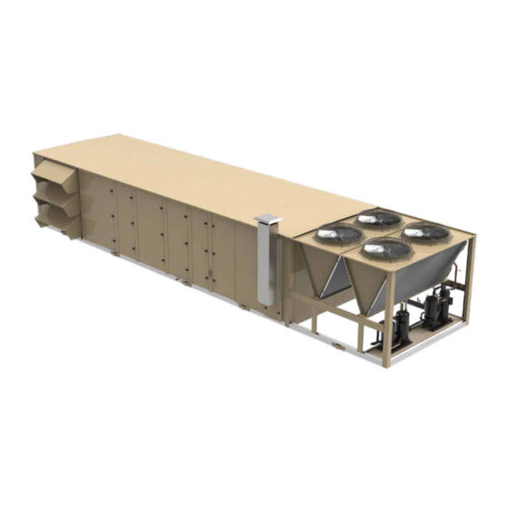
25-50 Tons
Premier Rooftop Units
R-410A
Nomenclature ...................................................................... 4
Pre Start-Up Checklist ......................................................... 7
Start-Up ............................................................................... 9
Long Term Storage ......................................................... 9
Unit Checks (Power Applied) ....................................... 10
Initial Start-Up .............................................................. 16
Refrigerant Charge ............................................... 16
Checking Sub-Cooling and Superheat.................. 16
Leak Checking ...................................................... 17
Gas Heat Models .................................................. 17
Phase Monitor Adjustment .................................... 20
Commissioning Mode................................................... 20
Air Balancing Wizard .................................................... 20
Start-Up Wizard ............................................................ 24
Start-Up Wizard Sequence ................................... 26
Sequences of Operation .................................................... 30
Control Boards ............................................................. 30
Variable Frequency Drives (VFDs) ............................... 37
Unit Type ...................................................................... 38
Occupancy Mode ......................................................... 38
Morning Warm-up/Cool Down ............................... 38
Coast..................................................................... 38
Remote Safety Shutdown ............................................ 39
Low Voltage Monitoring ................................................ 39
Supply Fan Operation .................................................. 39
Supply Fan Alarm.................................................. 39
MZVAV Supply Fan ............................................... 39
SZVAV Supply Fan ............................................... 40
Redundant Supply Fan VFD ................................. 40
Cooling Operation ........................................................ 40
MZVAV Cooling Operation .................................... 40
SZVAV Cooling Operation ..................................... 42
Compressors and Refrigeration Circuits ............... 42
OPERATION
&
Table of Contents
Compressor Staging Sequences .......................... 44
Condenser Systems and Fans.............................. 48
Dehumidification (Hot Gas Reheat) ...................... 49
Economizer ........................................................... 51
Heating ......................................................................... 52
Gas Heating .......................................................... 52
Electric Heating ..................................................... 56
Hydronic Heating .................................................. 56
MZVAV Heating Operation .................................... 56
SZVAV Heating Operation .................................... 57
Ventilation..................................................................... 58
Ventilation Sequences .......................................... 58
Low Mixed Air Temperature Limiting ..................... 58
Demand Control Ventilation .................................. 58
Continuous Ventilation .......................................... 59
Pre-Occupancy Purge........................................... 59
Humidification............................................................... 60
Humidification Sequence ...................................... 60
Exhaust System ........................................................... 60
Modulating Exhaust Fan ....................................... 60
Modulating Exhaust Damper with Fan .................. 60
External Control .................................................... 60
Return Fan ................................................................... 60
Return Fan Discharge Pressure ........................... 61
Supply Fan Airflow Tracking.................................. 61
Energy Recovery Wheel .............................................. 61
Single Speed Energy Recovery Wheel ................. 61
Variable Speed Energy Recovery Wheel .............. 61
Ultraviolet Lights........................................................... 61
Smoke Control ............................................................. 62
Purge .................................................................... 62
Pressurization ....................................................... 62
Depressurize ......................................................... 62
LD26877
5586996-JSG-A-0120
Advertisement
Table of Contents


Need help?
Do you have a question about the GVA Series and is the answer not in the manual?
Questions and answers