Hillrom LIFE2000 Ventilator Clinician Instructions For Use
Hide thumbs
Also See for LIFE2000 Ventilator:
- Quick start manual (22 pages) ,
- Setup manual (2 pages) ,
- Instructions for use manual (82 pages)
Table of Contents
Advertisement
Quick Links
Advertisement
Table of Contents
Troubleshooting

Subscribe to Our Youtube Channel
Related Manuals for Hillrom LIFE2000 Ventilator


Summary of Contents for Hillrom LIFE2000 Ventilator
- Page 1 LIFE2000® VENTILATOR Clinician Instructions for Use...
-
Page 3: Table Of Contents
CONTENTS CHAPTER 1: LIFE2000® VENTILATOR INTRODUCTION ___________________________________ 5 Indications for Use _______________________________________________________________________5 Symbols and Conventions __________________________________________________________________5 Safety Information ________________________________________________________________________6 Features _______________________________________________________________________________9 Identfying the REF number _________________________________________________________________9 Packaging Contents _____________________________________________________________________ 10 Essential Accessories ____________________________________________________________________ 10 Components ___________________________________________________________________________ 11 CHAPTER 2: VENTILATOR SETUP ___________________________________________________12 Ventilator Setup ________________________________________________________________________ 12 Testing the Ventilator ____________________________________________________________________ 12 Connecting to a Pressure Source ___________________________________________________________ 13... - Page 4 CONTENTS CHAPTER 4: VENTILATION SETTINGS ______________________________________________ 30 Introduction to Ventilation Settings __________________________________________________________30 Home Screen __________________________________________________________________________30 Moving Between the Home Screen and Menu Screen ____________________________________________ 31 Menu Screen __________________________________________________________________________ 31 Defining Clinical Settings __________________________________________________________________32 Disabling Access to the Clinician’s Settings Menu _______________________________________________32 Viewing and Editing Prescription Settings _____________________________________________________33 Factory Default Prescription Settings _________________________________________________________34 Breath Types __________________________________________________________________________35...
- Page 5 CONTENTS CHAPTER 5: ALARMS AND TROUBLESHOOTING ______________________________________ 57 Introduction to Alarms and Troubleshooting ____________________________________________________57 Alarm Sounds and Message Display _________________________________________________________58 Active Alarms Window ___________________________________________________________________58 Silencing and Clearing Alarms _____________________________________________________________ 59 Alarms ______________________________________________________________________________ 60 High-Priority Alarms ____________________________________________________________________ 60 Medium-Priority Alarms __________________________________________________________________ 60 Low-Priority Alarms _____________________________________________________________________ 60 Troubleshooting _______________________________________________________________________ 62 CHAPTER 6: MAINTENANCE ______________________________________________________ 67...
- Page 6 CONTENTS CHAPTER 8: ALTITUDE VOLUME ADJUSTMENT TABLE _________________________________ 89 CHAPTER 9: PRINCIPLES OF OPERATION ___________________________________________ 90 General Overview ______________________________________________________________________ 90 Operation Summary ____________________________________________________________________ 90 Pneumatic Diagram of the Life2000® Ventilator ________________________________________________ 90 CHAPTER 10: PERFORMANCE SPECIFICATIONS _______________________________________91 CHAPTER 11: COMPLIANCE AND IEC CLASSIFICATION _________________________________ 96 CHAPTER 12: ICONS ___________________________________________________________ 100 LIMITED WARRANTY ____________________________________________________________104...
-
Page 7: Chapter 1: Life2000® Ventilator Introduction
CHAPTER 1: LIFE2000® VENTILATOR INTRODUCTION INDICATIONS FOR USE The Life2000® Ventilator is intended to provide continuous or intermittent ventilatory support for the care of individuals who require mechanical ventilation. The ventilator is intended for use by qualified, trained personnel under the direction of a physician. Specifically, the ventilator is applicable for adult patients who require the following types of ventilatory support: •... -
Page 8: Safety Information
LIFE2000® VENTILATOR INTRODUCTION SAFETY INFORMATION Please read the following safety warnings and cautions in their entirety before using the Life2000® Ventilator. Warnings and cautions can also be found throughout this Instructions for Use . ! WARNING: • The Life2000® Ventilator is a restricted medical device intended for use by qualified, trained personnel under the direction of a physician. - Page 9 LIFE2000® VENTILATOR INTRODUCTION • For any accessories, read the label and accompanying document(s) before use. • Use only approved accessories and replacement parts with the ventilator. If unauthorized accessories or replacement parts are used with the ventilator, the ventilator may be damaged and performance may be degraded.
- Page 10 LIFE2000® VENTILATOR INTRODUCTION ! CAUTION: • No user serviceable components are inside the device. • Do not place the battery charger on wet surfaces or use in wet environments. Wet environments may damage the battery charger and may cause electric shock. •...
-
Page 11: Features
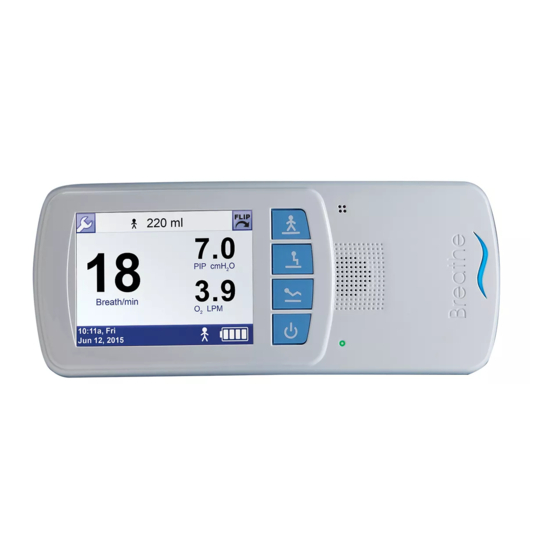
Displays patient breath rate, Peak Inspiratory Pressure (PIP), average flow, and current volume level. LIFE2000® VENTILATOR VERSIONS There are two released ventilator versions of the Life2000 Ventilator. You will be able to identify the version of the ventilator based on the REF number. -
Page 12: Packaging Contents
LIFE2000® VENTILATOR INTRODUCTION PACKAGING CONTENTS ! WARNING: For any accessories, read the label and accompanying document(s) before use. TIP: The ventilator is shipped in specially designed, protective boxes. Do not throw away the boxes; keep them for future transportation needs. Life2000®... -
Page 13: Components
LIFE2000® VENTILATOR INTRODUCTION COMPONENTS FRONT BOTTOM Battery charger connection Touch screen 11 Interface connection 2 Silence Alarm button 5 Prescription Settings buttons 12 Gas inlet connection Communication Port High Activity button Medium Activity button Low Activity button 6 Power button Power indicator light 8 Alarm speaker 9 Backup alarm speaker... -
Page 14: Chapter 2: Ventilator Setup
CHAPTER 2: VENTILATOR SETUP VENTILATOR SETUP This chapter provides information about powering on and securing the ventilator, and instructions for connecting the Life2000® Ventilator to a pressure source by using an oxygen hose or optional air hose. A regulator is required to connect the ventilator to an oxygen or air cylinder. An adapter may be required to connect to a wall source. -
Page 15: Connecting To A Pressure Source
VENTILATOR SETUP CONNECTING TO A PRESSURE SOURCE Connect the ventilator to a 50-PSI (nominal) medical grade oxygen or air pressure source, such as a wall source or cylinder, by using the Life2000 oxygen or air hose. Choose the appropriate hose for the source gas cylinder you will use. A 6 ft. oxygen hose is included with the ventilator and is compatible with medical oxygen pressure sources. -
Page 16: Connecting To A Source Gas Cylinder
VENTILATOR SETUP CONNECTING TO A SOURCE GAS CYLINDER A regulator is required to connect the ventilator to an oxygen or air cylinder. Ensure that the gas regulator meets the requirements below and is appropriate for the cylinder being used. REGULATOR REQUIREMENTS Pressure output 41-87 PSI (50 PSI nominal) Pressure flow... - Page 17 VENTILATOR SETUP Choose the appropriate hose for the source gas cylinder. 2 Visually inspect the oxygen or air hose for damage before using it. Ensure the ventilator is powered off. Connect the oxygen or air hose to the ventilator by pushing the small quick connect end of the hose onto the gas inlet connection on the ventilator;...
-
Page 18: Cylinder Duration Information
VENTILATOR SETUP CYLINDER DURATION INFORMATION The duration of compressed medical oxygen and air cylinders depends on the volume of the cylinder and the breathing pattern of each patient, which can change throughout the day. Observe daily air and/or oxygen consumption a few times before estimating typical use. The following tables can be used to obtain approximate values only. -
Page 19: Replacing The Source Gas Cylinder
VENTILATOR SETUP For other cylinder sizes or partially-filled cylinders, the following chart and equation can be used to estimate cylinder duration. GAS USAGE (LPM) CHART BREATHS PER MINUTE (BPM) Volume (ml) Gas Usage (LPM) 10.0 11.0 12.0 13.0 14.0 10.5 12.0 13.5 15.0... -
Page 20: Connecting To A Wall Pressure Source
VENTILATOR SETUP CONNECTING TO A WALL PRESSURE SOURCE To connect to your facility's medical gas wall sources, the Life2000 Ventilator oxygen hose requires a DISS 1240 fitting. An adapter may be required; examples of common adapters are provided below. ADAPTERS FOR OXYGEN WALL CONNECTIONS... -
Page 21: Securing The Ventilator
VENTILATOR SETUP SECURING THE VENTILATOR BELT CLIP You can attach the ventilator to a belt or waistband using the included belt clip. The ventilator can be worn on either the right or left side. ! CAUTION: • Make sure the clip is securely fastened to the belt and the ventilator. If the clip is not securely fastened to the belt and the ventilator, the ventilator may fall and be damaged. -
Page 22: Pole Mount
VENTILATOR SETUP POLE MOUNT You can attach the ventilator to a pole or railing using an optional pole mount. For information about ordering accessories and replacement parts, see "Accessories and Replacement Parts" on page 88. ! CAUTION: • Make sure the pole mount is securely attached to the pole, and the ventilator and clip are securely fastened to the pole mount and the ventilator. -
Page 23: Powering On Sequence
VENTILATOR SETUP POWERING ON SEQUENCE Power on the ventilator by pressing the power button. 2 Ensure that the green power indicator light is on. When the startup screen is displayed, listen for audible tones to test the alarm speaker. During the start up sequence, the ventilator will perform a self test. During the test, all indicator lights should briefly flash and an audible alarm should briefly sound. -
Page 24: Checking The Battery Charge
VENTILATOR SETUP CHECKING THE BATTERY CHARGE BATTERY CHARGE ICONS AND APPROXIMATE TIME REMAINING Ensure that the ventilator is powered on. Check the Ventilator Battery Charge icon on the touch screen to see the current battery charge level for the ventilator. Refer to the chart below to determine the approximate amount of ventilator battery charge. -
Page 25: Charging The Ventilator
VENTILATOR SETUP CHARGING THE VENTILATOR Plug the AC power cord into the battery charger. 2 Connect the AC plug into an AC power source. The battery charger indicator light will turn green or red when connected to AC power. Connect the battery charger cord to the battery charger connection port. The word "UP" on the battery charger cord will be on top. -
Page 26: Powering Off Sequence For The Ventilator
VENTILATOR SETUP POWERING OFF SEQUENCE FOR THE VENTILATOR To power off the ventilator, press the Power button for three seconds until a confirmation screen appears. 2 To continue to power off the ventilator, choose OK. NOTE: If a selection is not made within 20 seconds or if the BACK button is selected, the previous screen will be displayed and the ventilation status will not be affected. -
Page 27: Chapter 3: Connecting The Interface
CHAPTER 3: CONNECTING THE INTERFACE THE BREATHE PILLOWS INTERFACE® The Life2000® Ventilator requires the use the Breathe Pillows Interface®. The Breathe Pillows Interface® is only compatible with Hillrom ventilators. ™ The non-invasive Breathe Pillows Interface® connects directly to the ventilator and is available in four sizes: extra small, small, medium, and large. -
Page 28: Using The Breathe Pillows Interface
CONNECTING THE INTERFACE USING THE BREATHE PILLOWS INTERFACE® Before using the Breathe Pillows Interface®, visually inspect it for damage. ! CAUTION: Do not use a Breathe Pillows Interface® that is cracked, odorous, broken, or kinked. If a damaged interface is used, the patient may not receive adequate respiratory therapy. -
Page 29: Wearing The Breathe Pillows Interface
CONNECTING THE INTERFACE WEARING THE BREATHE PILLOWS INTERFACE® 1 Place the interface in front of the patient with the arrows underneath pointing up and the curve of the interface towards the patient’s face. 2 Loop the interface tubing over the ears so the nasal pillows are positioned snugly inside the nostrils. Using the tube fit adjuster (cinch), adjust the interface tubing length under the chin so that the interface is secured snugly and comfortably. -
Page 30: Connecting The Universal Circuit Connector
CONNECTING THE INTERFACE THE BREATHE UNIVERSAL CIRCUIT® CONNECTOR The Universal Circuit Connector is used to connect any commercially available non-invasive mask (full face, nasal, or pillows) or tracheostomy tube to a Breathe Technologies® ventilator or compressor. The Universal Circuit Connector is only compatible with the Life2000 ventilator. - Page 31 NOTES: • When the Life2000 ventilator is interfaced with a Vented Full Face Mask, for PEEP settings above 3 cmH2O, the Ventilator can tolerate up to 37 LPM of intentional or unintentional leak. • When adding any componets to the breathing system, the flow, resistance, and deadspace of the added components such as Heat and Moisture Exchanger (HME) and Filters should be considered in relation to the performance of the ventilator and alarms..
-
Page 32: Chapter 4: Ventilation Settings
CHAPTER 4: VENTILATION SETTINGS INTRODUCTION TO VENTILATION SETTINGS All of the clinical and utility menus can be accessed, viewed, and edited by the touch screen on the ventilator. To use the touch screen, simply touch a button or an area of the screen you want to make active. An audible “click”... -
Page 33: Moving Between The Home Screen And Menu Screen
VENTILATION SETTINGS MOVING BETWEEN THE HOME SCREEN AND MENU SCREEN 500 ml 20.0 PIP cmH Breath/min Air LPM 10:11a, Fri Jun 12, 2015 Touch the Wrench Button to go to the Menu Screen. 10:11a, Fri Jun 12, 2015 2 Touch the Home Screen button to go to the Home Screen. MENU SCREEN Use the Menu screen to go to the Settings menu, get information about the ventilator’s software version and total operating time, or go back to the Home Screen. -
Page 34: Defining Clinical Settings
VENTILATION SETTINGS DEFINING CLINICAL SETTINGS 10:11a, Fri Jun 12, 2015 On the Menu screen, touch Settings. 10:11a, Fri Jun 12, 2015 2 On the Settings Menu screen, touch Clinician’s Settings. NOTE: Access to the Clinician’s Settings menu is restricted to trained clinical personnel. 10:11a, Fri Jun 12, 2015 On the Clinician Password screen, enter the password. -
Page 35: Viewing And Editing Prescription Settings
VENTILATION SETTINGS VIEWING AND EDITING PRESCRIPTION SETTINGS The buttons on the Prescription Settings screen correspond to the Low Activity, Medium Activity, and High Activity Prescription Settings buttons on the ventilator. Patients will then be able to press an Activity button to select their therapy. -
Page 36: Factory Default Prescription Settings
VENTILATION SETTINGS FACTORY DEFAULT PRESCRIPTION SETTINGS The following table lists the Life2000® factory default Prescription Settings that may be edited. For a full list of factory defaults, see the "Summary of Factory Default Settings" on page 56. DEFAULT VALUE DESCRIPTION MEDIUM HIGH ACTIVITY... -
Page 37: Breath Types
VENTILATION SETTINGS BREATH TYPES There are two breath types that apply to the Volume Control ventilation provided by the ventilator: • Mandatory • Assisted MANDATORY BREATH A mandatory breath (or machine breath) is completely controlled by the ventilator. The ventilator controls both the beginning (triggering) and end (cycling) of the inspiratory phase. -
Page 38: Setting Ventilation Parameters In Control Ventilation Mode
VENTILATION SETTINGS SETTING VENTILATION PARAMETERS IN CONTROL VENTILATION MODE In this mode, the ventilator delivers volume control therapy only for mandatory breaths. A mandatory breath is delivered according to the breath rate setting (BR). This also means that a breath will not be triggered based on patient’s inspiratory effort. - Page 39 VENTILATION SETTINGS To set a Prescription Setting for Control Ventilation Mode, the following parameters need to be set according to the table below: VENTILATION MODE* SET TRIGGER SENSITIVITY TO: SET BREATH RATE TO: Control ≥ 1 *SETTINGS BASED ON PRESCRIPTION To set the Prescription Setting: Clinician’s Settings Ventilation...
-
Page 40: Setting Ventilation Parameters In Assist/Control Ventilation Mode
VENTILATION SETTINGS SETTING VENTILATION PARAMETERS IN ASSIST/CONTROL VENTILATION MODE In this mode, the ventilator provides tidal volume during inhalation for assisted and mandatory breaths. An assisted breath is started when there is patient effort, but it is ended when the inspiratory time (I-Time) setting has been met. - Page 41 VENTILATION SETTINGS To set a Prescription Setting for Assist/Control ventilation mode, the following parameters need to be set according to the table below: VENTILATION MODE* SET TRIGGER SENSITIVITY TO: SET BREATH RATE TO: Assist/Control 0 to 9 ≥ 1 *SETTINGS BASED ON PRESCRIPTION To set the Prescription Setting: Clinician’s Settings Ventilation...
-
Page 42: Setting Ventilation Parameters In Assist Ventilation Mode
VENTILATION SETTINGS SETTING VENTILATION PARAMETERS IN ASSIST VENTILATION MODE In this mode, the ventilator provides tidal volume during inhalation for assisted breaths. An assisted breath is started when there is patient effort and is ended when the inspiratory time (I-Time) setting has been met. If the ventilator does not detect breaths during the allotted time as defined by the breath Timeout Period, the ventilator will deliver breaths or a continuous flow of gas based on the Timeout Action setting. - Page 43 VENTILATION SETTINGS To set a Prescription Setting for Assist ventilation mode, the following parameters need to be set according to the table below: VENTILATION MODE* SET TRIGGER SENSITIVITY TO: SET BREATH RATE TO: Assist 0 to 9 *SETTINGS BASED ON PRESCRIPTION To set the Prescription Setting: Clinician’s Settings Ventilation...
- Page 44 VENTILATION SETTINGS VENTILATION SETTINGS SUMMARY PARAMETER MINIMUM MAXIMUM INCREMENT Volume (ml) I-Time (sec)) 3.00 PEEP (cmH Sensitivity Control ventilation mode: Control ventilation mode: Assist or Assist/Control Assist or Assist/Control ventilation mode: 9 ventilation mode: 0 BR (/min) TIPS: • Volume: You can set an output volume between 50 ml and 750 ml, in increments of 10 ml. NOTE: Volume levels are not adjusted for altitude.
-
Page 45: Setting Alarm Limits For Breath Rate And Pip
VENTILATION SETTINGS SETTING ALARM LIMITS FOR BREATH RATE AND PIP To view or edit critical alarms, access the Alarm Limits screen from the Clinician’s Settings screen. Clinician’s Settings Ventilation Alarm Breath Settings Limits Timeout Source 10:11a, Fri 10:11a, Fri Jun 12, 2015 Jun 12, 2015 On the Clinician's Settings screen, touch Alarm Limits. -
Page 46: Setting Breath Timeout (Apnea Backup Ventilation Mode)
VENTILATION SETTINGS SETTING BREATH TIMEOUT (APNEA BACKUP VENTILATION MODE) Clinician’s Settings Ventilation Alarm Breath Settings Limits Timeout Source 10:11a, Fri 10:11a, Fri Jun 12, 2015 Jun 12, 2015 On the Clinician’s Settings screen, touch Breath Timeout. Breath Timeout 10:11a, Fri 10:11a, Fri Jun 12, 2015 Jun 12, 2015... -
Page 47: Selecting The Source Gas
VENTILATION SETTINGS SELECTING THE SOURCE GAS The Life2000® Ventilator uses O (oxygen) as the factory set default source gas. If using air, select Air as the Source Gas. Clinician’s Settings Ventilation Alarm Breath Settings Limits Timeout Source 10:11a, Fri Jun 12, 2015 On the Clinician’s Settings screen, touch Source Gas. -
Page 48: Choosing A Prescription Setting Button
VENTILATION SETTINGS CHOOSING A PRESCRIPTION SETTING BUTTON When the ventilator is first powered on, you must select an Prescription Setting button to begin therapy. The three Prescription Setting buttons on the ventilator are programmed to correspond to up to three different prescriptions as directed by a physician. -
Page 49: This Prescription Setting Is Not Active" Message
VENTILATION SETTINGS “THIS PRESCRIPTION SETTING IS NOT ACTIVE” MESSAGE This Prescription Setting is not active. 10:11a, Fri Jun 12, 2015 If the Prescription Setting button selected on the ventilator is not active, this message will appear on the touch screen. If therapy already began with a different Prescription Setting, the ventilator will continue delivering therapy using the previous Prescription Setting. -
Page 50: Adjusting The Trigger Sensitivity
VENTILATION SETTINGS ADJUSTING THE TRIGGER SENSITIVITY Trigger sensitivity determines how easily a patient’s inspiratory effort triggers the breath delivery. For shallow breathing, set the trigger sensitivity to a low number. You can choose a setting between 0 and 9. Zero is the most sensitive and 9 is the least sensitive setting. -
Page 51: Changing Trigger Sensitivity
VENTILATION SETTINGS CHANGING TRIGGER SENSITIVITY 10:11a, Fri Jun 12, 2015 While ventilating, on the Trigger Sensitivity screen, touch the Up Arrow to increase the value or the Down Arrow to decrease it. If you press and hold an arrow, the number automatically increases or decreases. NOTE: The lower the number, the more sensitive the setting. -
Page 52: Accessing The Utilities Menu
VENTILATION SETTINGS ACCESSING THE UTILITIES MENU With the Utilities menu, you can change the time and date, brightness of the touch screen, volume of audible alarms, and set alarm notifications for vibration. 500 ml 20.0 PIP cmH Breath/min Air LPM 10:11a, Fri Jun 12, 2015 On any screen, touch the Wrench Button. -
Page 53: Setting Time And Date
VENTILATION SETTINGS SETTING TIME AND DATE Customize the time and date that appear on the ventilator. 10:11a, Fri Jun 12, 2015 On the Utilities Menu screen, touch Set Time/Date. 10:11a, Fri Jun 12, 2015 2 On the Set Time/Date screen, touch the box you want to change. 10:11a, Fri Jun 12, 2015 Touch the Up Arrow to increase the value in the box or the Down Arrow to decrease it. -
Page 54: Setting Vibration
VENTILATION SETTINGS SETTING VIBRATION The Set Vibration screen lets you change alarm notifications from audible tones to a vibration. However, if a low- or medium-priority vibrating alarm occurs and is not resolved in 60 seconds, an audible alarm occurs. For a high- priority alarm, an audible tone immediately occurs with a vibration alarm with no delay. -
Page 55: Setting Loudness
VENTILATION SETTINGS SETTING LOUDNESS Loudness settings represent the audio volume of the ventilator's alarm notifications. Set the alarm volume settings to a value that can be heard by the user in the environment that it is being used. ! WARNING: Reducing the alarm loudness level to lower than the ambient sound level will impede alarm condition recognition. -
Page 56: Adjusting Screen Brightness
VENTILATION SETTINGS ADJUSTING SCREEN BRIGHTNESS Set the screen brightness to improve readability or adjust for changing viewing conditions. 10:11a, Fri Jun 12, 2015 On the Utilities Menu screen, touch Set Brightness. 10:11a, Fri Jun 12, 2015 2 Touch the Up Arrow to increase the brightness or the Down Arrow to decrease it. If you press and hold an arrow, the number automatically increases or decreases. -
Page 57: Viewing Software Version Information
On the Menu screen, touch Information. 10:11a, Fri Jun 12, 2015 Information The screen displays information about the ventilator and its operation. Life2000 Ventilator • Software Version is the version of software currently running on the Software Version BT-V5 XX.XX.XX.XX ventilator. -
Page 58: Summary Of Factory Default Settings
VENTILATION SETTINGS SUMMARY OF FACTORY DEFAULT SETTINGS The following table lists the factory default settings for the ventilator. DEFAULT VALUE CLINICIAN’S MENU SETTINGS MEDIUM HIGH ACTIVITY ACTIVITY ACTIVITY Ventilation Settings Volume 150 ml 180 ml 200 ml I-Time (Inspiratory Time) .75 sec PEEP (Positive End Expiratory Pressure) 0 cmH... -
Page 59: Chapter 5: Alarms And Troubleshooting
CHAPTER 5: ALARMS AND TROUBLESHOOTING INTRODUCTION TO ALARMS AND TROUBLESHOOTING ! WARNING: • If the Life2000® Ventilator is not functioning properly, respiratory therapy may be compromised and may result in patient harm or death. Always have an alternate means of ventilation or oxygen therapy available. •... -
Page 60: Alarm Sounds And Message Display
ALARMS AND TROUBLESHOOTING ALARM SOUNDS AND MESSAGE DISPLAY When an alarm notification occurs there is a distinct sound and a display message corresponding to the priority level of the alarm. The priority level of an alarm is indicated by the color and the rate at which the message flashes. -
Page 61: Silencing And Clearing Alarms
ALARMS AND TROUBLESHOOTING SILENCING AND CLEARING ALARMS Silencing and clearing alarms is a multi-step process that depends on alarm priority and the number of active alarms. Press the Silence Alarm button to temporarily silence the alarm for 60 seconds. Pressing the Silence Alarm button silences only one alarm at a time. -
Page 62: Alarms
ALARMS AND TROUBLESHOOTING ALARMS The following tables list high-, medium-, and low-priority alarms. For each alarm, the tables list the notification, the possible causes for the alarm, and possible options for resolving it. The sample screens are for illustrative purposes only. NOTES: •... - Page 63 ALARMS AND TROUBLESHOOTING MEDIUM-PRIORITY ALARMS NOTIFICATION CAUSE CHECKS AND POSSIBLE RESOLUTION Battery Low Ventilator battery capacity Connect the ventilator to the battery charger and an AC drops below 25%. power source to recharge the battery. Breath Timeout No breath is detected Patient is not breathing.
- Page 64 ALARMS AND TROUBLESHOOTING MEDIUM-PRIORITY ALARMS (CONTINUED) NOTIFICATION CAUSE CHECKS AND POSSIBLE RESOLUTION Low Breath Rate Respiratory rate falls below Patient is breathing through the mouth while using the set limit. Breathe Pillows Interface®. Breaths are too shallow to trigger ventilation; change the trigger sensitivity to a lower setting (higher sensitivity).
- Page 65 ALARMS AND TROUBLESHOOTING LOW-PRIORITY ALARMS NOTIFICATION CAUSE CHECKS AND POSSIBLE RESOLUTION POST System Fault System fault is detected Power off the ventilator, and power it on during ventilator power on. again. If the system fault persists, place the patient on an alternate means of ventilation (if necessary) and contact your service representative •...
-
Page 66: Troubleshooting
ALARMS AND TROUBLESHOOTING TROUBLESHOOTING The following table lists situations that may occur during normal use of the ventilator that do not have an alarm associated with them. The possible causes and options for resolving these situations are also listed. NOTES: •... - Page 67 ALARMS AND TROUBLESHOOTING TROUBLESHOOTING (CONTINUED) NOTIFICATION CAUSE CHECKS AND POSSIBLE RESOLUTION Breath indicator light is Ventilator is not on. Ensure ventilator is on. not flashing and there A ventilator Prescription Setting Press a Prescription Setting button. is no volume output button has not been pressed.
- Page 68 ALARMS AND TROUBLESHOOTING TROUBLESHOOTING (CONTINUED) NOTIFICATION CAUSE CHECKS AND POSSIBLE RESOLUTION The oxygen or air hose An incorrect source gas supply Ensure you are using the correct approved gas does not connect to hose is being used. supply hose (oxygen or air). the gas source.
-
Page 69: Chapter 6: Maintenance
Absence of false alarms • No interruption of operation without alarms. Do not use, or discontinue use of the ventilator, if damage is discovered. For instructions on servicing or replacing damaged ventilator components, contact your Hillrom service representative. ™ ENVIRONMENTAL SPECIFICATIONS Do not use the ventilator if the ambient temperature is greater than 40°C (104°F) or less than 5°C (41°F). -
Page 70: Alarm Checks
MAINTENANCE ALARM CHECKS Confirm that when the ventilator is powered on, it makes audible tones. If tones are not heard, the ventilator should be returned to your service representative CLEANING AND DISINFECTING THE VENTILATOR • Using a clean cloth, clean and disinfect the external surfaces of the ventilator with 70% isopropyl alcohol or PDI Super Sani-Cloth®... -
Page 71: Cleaning For Single Patient Use
MAINTENANCE CLEANING FOR SINGLE PATIENT USE VENTILATOR Once a week, or more often if necessary, follow the instructions found in the “Cleaning and Disinfecting the Ventilator” section of this chapter. BREATHE PILLOWS INTERFACE® Once a week, or more often if necessary, follow the instructions found in the “Cleaning the Breathe Pillows Interface®”... -
Page 72: Cleaning For Multi-Patient Use
MAINTENANCE CLEANING FOR MULTI-PATIENT USE ! WARNING: To prevent risk of cross-contamination, clean and disinfect the ventilator before using it on a new patient, and use a new Breathe Pillows Interface®. In addition to the cleaning and maintenance instructions for single-patient use, you must perform the following before the ventilator is provided to a new patient. -
Page 73: Cleaning The Breathe Pillows Interface
MAINTENANCE CLEANING THE BREATHE PILLOWS INTERFACE® ! WARNING: Do not subject the Breathe Pillows Interface® to heat sterilization, hot water pasteurization, autoclaving, radiation sterilization, ethylene oxide gas sterilization, or attempt to clean it in a dishwasher or microwave oven. Doing any of these may damage the interface and impair gas delivery. -
Page 74: Purging The Breathe Pillows Interface
MAINTENANCE PURGING THE BREATHE PILLOWS INTERFACE® After cleaning and completely drying the interface or when you suspect dust or debris has entered the airflow passage, purge the interface with the purge tube and either a wall pressure source (with a flow meter) or a NOTE: cylinder. -
Page 75: Purging Using A Cylinder
MAINTENANCE PURGING USING A CYLINDER Purging with a cylinder requires a flow regulated barbed output. The instructions below are provided as an example of purging using a regulator with an integrated flow regulated barbed output. Refer to the regulator and source gas supply manufacturers’ instructions for more information about how to connect the cylinder and regulator;... -
Page 76: Preventive Maintenance
MAINTENANCE PREVENTIVE MAINTENANCE ! WARNING: Unauthorized modifications can result in equipment damage, or patient injury or death. ! CAUTION: No user serviceable components are inside the device. Contact your service representative to make arrangements for preventive maintenance, service, and component replacement 2.5 years from the date of shipment. -
Page 77: Testing Ventilator Alarms
MAINTENANCE TESTING VENTILATOR ALARMS This section gives instructions for testing ventilator alarms. Procedures described in this section are only to be performed by trained personnel. Connect the ventilator to an AC power source or ensure the battery has sufficient charge before beginning testing. -
Page 78: Checking Alarm Conditions
MAINTENANCE CHECKING ALARM CONDITIONS Do not test while the ventilator is being used on a patient. These testing procedures require clinical settings to be changed. If necessary, record clinical settings before beginning. For each test verify both corresponding alarm notifications occur and are correct: The visual alarm appears on the touch screen, and 2 The audio alarm is audible, or the ventilator vibrates if set for vibration. - Page 79 MAINTENANCE TESTING SETUP Power on the ventilator. If necessary, record clinical settings before changing settings. 2 Using the Clinician’s Menu, activate only the Low Activity Prescription Setting. Set the Ventilation Settings to: Set the Alarm Limits to: Set the Breath Timeout to: Ventilation Settings FLIP Volume...
- Page 80 MAINTENANCE 1. TESTING THE HIGH GAS PRESSURE ALARM (MEDIUM PRIORITY) Begin by ventilating using the Low Activity Prescription Setting. Allow the ventilator to ventilate for a few breaths. 2 With the source gas supply on and connected to the ventilator and an adjustable regulator, set the regulator to 95 PSI.
- Page 81 MAINTENANCE 2. TESTING THE LOW GAS PRESSURE ALARM (MEDIUM PRIORITY) Begin by ventilating using the Low Activity setting. Allow the ventilator to ventilate for a few breaths. 2 Disconnect the source gas supply hose from the ventilator connection by pulling back on the knurled ring until the hose detaches.
- Page 82 MAINTENANCE 4. TESTING THE LOW PIP PRESSURE ALARM (MEDIUM PRIORITY) AND LOW DELIVERY PRESSURE ALARM (MEDIUM PRIORITY) Begin by ventilating using the Low Activity setting. Continue to use the current Ventilation Settings. Allow the ventilator to ventilate for a few breaths. 2 Disconnect the interface from the ventilator.
- Page 83 MAINTENANCE 5. TESTING THE HIGH PIP PRESSURE ALARM (HIGH PRIORITY) Begin by ventilating using the Low Activity setting. Continue to use the current Ventilation Settings. Allow the ventilator to ventilate for a few breaths. 2 Using the Clinician’s Settings Menu, navigate to Alarm Limits and change the High PIP alarm limit to 10 O.
- Page 84 MAINTENANCE 6. TESTING THE BREATH TIMEOUT ALARM (MEDIUM PRIORITY) AND HIGH CIRCUIT PRESSURE ALARM (HIGH PRIORITY) Begin by ventilating using the Low Activity setting. Allow the ventilator to ventilate for a few breaths. Ventilation Settings FLIP Volume 0.75 I-Time PEEP Sensitivity 0-9, OFF CANCEL...
- Page 85 MAINTENANCE 6 After verifying the correct alarm notifications for the High Circuit Pressure alarm, release the interface tubing and allow the High Circuit Pressure alarm to resolve itself. Touch OK in the message that indicates the alarm has been resolved. Ventilation Settings FLIP Volume...
- Page 86 MAINTENANCE 7. TESTING THE HIGH BREATH RATE ALARM (MEDIUM PRIORITY) Begin by ventilating using the Low Activity setting. Continue to use the current Ventilation Settings. Allow the ventilator to ventilate for a few breaths. 2 Using the Clinician’s Settings Menu, navigate to Alarm Limits and change the High BR alarm limit to 20/min. Select OK and CONFIRM.
- Page 87 MAINTENANCE 8. TESTING THE LOW BREATH RATE ALARM (MEDIUM PRIORITY) Begin by ventilating using the Low Activity setting. Continue to use the current Ventilation Settings. Allow the ventilator to ventilate for a few breaths. 2 Using the Clinician’s Settings Menu, navigate to Alarm Limits and change the Low BR alarm limit to 20/min. Select OK and CONFIRM.
- Page 88 MAINTENANCE 9. TESTING THE BATTERY LOW ALARM (MEDIUM-PRIORITY) AND VERY LOW BATTERY ALARM (HIGH-PRIORITY) If the ventilator is connected to an AC power source, disconnect the ventilator from the power source so it is running on its internal battery. 2 Ventilate by using the High Activity Setting. Allow the ventilator to ventilate until the Battery Low Alarm occurs (25% battery charge).
-
Page 89: Chapter 7: Accessories
CHAPTER 7: ACCESSORIES OXYGEN MONITOR ! WARNING: To ensure accuracy of oxygen administration and to monitor for the presence of contamination (incorrect gas connected), use an external oxygen monitor to verify the oxygen concentration in the delivered gas. If the patient requires oxygen monitoring, use the appropriate equipment. Sampling should be taken from the connection to the patient interface. -
Page 90: Accessories And Replacement Parts
ACCESSORIES ACCESSORIES AND REPLACEMENT PARTS ! WARNING: For any accessories, read the label and accompanying document(s) before use. PART NUMBER PRODUCT DESCRIPTION Interfaces (for single patient use only) BT-60-0013 Breathe Entrainment Pillows Interface®, Extra Small BT-60-0014 Breathe Entrainment Pillows Interface, Small BT-60-0015 Breathe Entrainment Pillows Interface, Medium BT-60-0016... -
Page 91: Chapter 8: Altitude Volume Adjustment Table
CHAPTER 8: ALTITUDE VOLUME ADJUSTMENT TABLE ALTITUDE VOLUME ADJUSTMENT TABLE The volume output by the ventilator is not automatically adjusted for altitude. The following table shows the actual volume output for several volume settings at different altitudes. Check the performance of the ventilator for adequate therapy delivery in the environment(s) in which it will be used and adjust the volume to compensate for altitude when necessary. -
Page 92: Chapter 9: Principles Of Operation
CHAPTER 9: PRINCIPLES OF OPERATION GENERAL OVERVIEW The Life2000® Ventilator utilizes an electromechanical pneumatic system under the control of a microprocessor to deliver patient ventilation. The following description and diagram illustrate the major components of the ventilator. OPERATION SUMMARY The ventilator uses pressurized air or pressurized oxygen (see diagram below). Air or oxygen enters through an inlet filter. -
Page 93: Chapter 10: Performance Specifications
CHAPTER 10: PERFORMANCE SPECIFICATIONS The Life2000® Ventilator is classified per IEC 60601-1 as portable, Class II, Type BF, continuous operation. The ventilator is not IP rated for ingress of liquids; keep dry. PERFORMANCE SPECIFICATIONS PARAMETER DESCRIPTION General Information Available ventilation modes Volume ventilation with Control, Assist/Control, and Assist ventilation modes Connection to patient Breathe Pillows Interface®... - Page 94 PERFORMANCE SPECIFICATIONS PARAMETER DESCRIPTION Means of initiating and Control ventilation mode: The inspiratory phase is started and terminated by the terminating inspiratory ventilator based on set respiratory rate and inspiratory time. phases Assist/Control ventilation mode: The inspiratory phase is started based on the patient’s breath triggering or by the ventilator based on set respiratory rate and terminated by the set inspiratory time.
- Page 95 Approximately 5-6 hours* Approx. Time Remaining based on the following ventilator settings: BR 12, Volume 350, PEEP 0, I-Time 1.0 If the battery performance degrades to unacceptable levels before the scheduled 2.5 year replacement, contact your Hillrom service representative. ™...
- Page 96 PERFORMANCE SPECIFICATIONS Power Cord 6 ft. IEC 320-E7 compliant cord PARAMETER DESCRIPTION Special Features Instead of an audio alarm, the user can enable the alarm to vibrate for medium- Alarm vibrate and low-level alarms. Touch screen flip User can flip the screen orientation 180°. Ventilator Alarm Notifications At maximum loudness setting: 73 db(A) High Priority Alarm...
- Page 97 PERFORMANCE SPECIFICATIONS 10 PARAMETER DESCRIPTION Physical Features Ventilator weight Approximately 1 lb. (excluding source gas and accessories) Ventilator size 3 1/8” x 1 1/4” x 7 1/2” Latex The ventilator does not contain natural rubber latex. Storage and Transport Environment Storage &...
-
Page 98: Chapter 11: Compliance And Iec Classification
The Life2000® Ventilator needs special precautions regarding electromagnetic compatibility (EMC) and needs to be installed and put into service according to the EMC information provided in this manual. The use of accessories, transducers and cables other than those specified by Hillrom may result in increased ™... - Page 99 COMPLIANCE AND IEC CLASSIFICATION 11 GUIDANCE AND MANUFACTURER’S DECLARATION: ELECTROMAGNETIC IMMUNITY The Life2000® Ventilator is intended for use in the electromagnetic environment specified below. The customer or user of the ventilator should ensure that it is used in such an environment. Immunity Test IEC 60601 Compliance...
- Page 100 COMPLIANCE AND IEC CLASSIFICATION GUIDANCE AND MANUFACTURER’S DECLARATION: ELECTROMAGNETIC IMMUNITY The Life2000® Ventilator is intended for use in the electromagnetic environment specified below. The customer or user of the ventilator should ensure that it is used in such an environment. LIFE2000®...
- Page 101 COMPLIANCE AND IEC CLASSIFICATION 11 RECOMMENDED SEPARATION DISTANCES BETWEEN PORTABLE AND MOBILE RF COMMUNICATION EQUIPMENT AND THE LIFE2000® VENTILATOR The Life2000® Ventilator is intended for use in an electromagnetic environment in which radiated RF disturbances are controlled. The clinician can help prevent electromagnetic interferences by maintaining a minimum distance between portable and mobile RF communications equipment (transmitters) and the ventilator as recommended in this table, according to the maximum output power of the communications equipment.
-
Page 102: Chapter 12: Icons
CHAPTER 12: ICONS ICON WHERE USED MEANING Ventilator Indicates communication port. This port is only used by the manufacturer. Ventilator Indicates power-in port. Ventilator and Indicates direct current. compressor Ventilator, The Silence Alarm button silences a vibration or audible alarm for 60 ventilator label, and seconds. - Page 103 ICONS 12 ICON WHERE USED MEANING Ventilator touch Displayed on touch screen if ventilator battery status is unknown or charge is screen critically low (< 5%). Ventilator touch Displayed on touch screen if ventilator battery has approximately 5-14% of its screen charge remaining.
- Page 104 ICONS ICON WHERE USED MEANING Ventilator label, Indicates disposal of device must conform to WEEE Directive (Waste in compressor label, Electrical and Electronic Equipment) 2011/65/EU. compressor external power supply Ventilator battery This symbol is used to support the Battery Directive 2006/66/EC. charger label Ventilator battery Indicates the battery charger meets European Economic Area standards for...
- Page 105 ICON WHERE USED MEANING Compressor Indicates compliance with RoHS. external power supply Compressor Indicates the unlocking knob is in the unlocked position. Compressor When lit, indicates the locking knob is in the locked position. Compressor Battery Charge Status button Compressor Power on/off button Ventilator Power on/off button...
-
Page 106: Limited Warranty
LIMITED WARRANTY LIMITED WARRANTY Breathe Technologies, Inc., a Hillrom warrants that the Life2000® ventilators will be free from defects in material and ™ workmanship for a period of one (1) year from the date of shipment. Products that are repaired or replaced under this Limited Warranty will be covered by this Limited Warranty for the greater of the remaining balance of the original warranty or ninety (90) days. - Page 107 The information contained in this document is of a proprietary and confidential nature and is intended only for the persons to whom it is directly transmitted by Breathe Technologies, Inc, a Hillrom Company. No part of this manual may be reproduced or transmitted in any form or by any means, electronic or mechanical, including photocopying and recording, for any purpose without the express written permission of Breathe Technologies, Inc.
- Page 108 Hillrom Technical Support and Customer Service ™ 1020 West County Road F 800-426-4224 St. Paul, MN 55126 PL-20-0049 Rev A ©2020. Breathe, Breathe Technologies, and Life2000 are trademarks of Breathe Technologies, Inc., a Hillrom Company...
Need help?
Do you have a question about the LIFE2000 Ventilator and is the answer not in the manual?
Questions and answers