Table of Contents
Advertisement
Quick Links
Advertisement
Table of Contents
Troubleshooting

Related Manuals for Hillrom Breathe LIFE2000


Summary of Contents for Hillrom Breathe LIFE2000
- Page 1 LIFE2000® VENTILATION SYSTEM Instructions for Use Rx Only...
-
Page 2: Table Of Contents
During this emergency and while the policy is in effect, FDA does not intend to object to limited modifications to Features _______________________________________________________________________________5 the FDA-cleared indications without prior submission of a 510(k) where the modifications do not create undue risks. Hillrom does not yet have FDA 510(k) clearance on the use of The Life2000 Ventilator Software version Packaging Contents ______________________________________________________________________6 ®... - Page 3 CONTENTS CONTENTS CHAPTER 6: VENTILATION SETTINGS ______________________________________________ 49 Checking the Compressor’s Internal Battery Status _____________________________________________ 29 Introduction to Ventilation Settings __________________________________________________________49 Assembling the Ventilator Battery Charger and Charging the Ventilator___ ___________________________ 30 Home Screen __________________________________________________________________________49 Securing the Ventilator_______________________________________ ___________ _________________31 Moving Between the Home Screen and Menu Screen ___________________________________________ 50 Belt Clip______________________________________________ ___________ _____________________31 Menu Screen _________________________________________________________________________ 50...
- Page 4 CONTENTS CONTENTS CHAPTER 7: ALARMS, ALERTS, AND TROUBLESHOOTING_______ ________ __________________ 78 Compressor Battery Charge Status _________________________________________________________ 126 Compressor Battery Specifications ______ ___________________________________________________127 Introduction to Alarms and Alerts__________________________________ _________ ___________________ 78 Ventilator On-Screen Alarm Sounds and Message Display_____________ __________ _____________________79 Ventilator Battery Charger and Power Cord Specifications__________________________________ ______ 128 Active Alarms Window_______________________________________ __________ ______________________79 Compressor Power Supply and Power Cord Specifications_________________________________ ______ 128 Silencing and Clearing On-Screen Alarms________________________ ________________________________80...
-
Page 5: Indications For Use
LIFE2000 VENTILATION SYSTEM INTRODUCTION LIFE2000 VENTILATION SYSTEM INTRODUCTION INDICATIONS FOR USE SAFETY INFORMATION The Life2000® Ventilation System is intended to provide continuous or intermittent ventilatory support for the care Please read the following safety warnings and cautions in their entirety before using the Life2000® Ventilation of individuals who require mechanical ventilation. - Page 6 LIFE2000 VENTILATION SYSTEM INTRODUCTION LIFE2000 VENTILATION SYSTEM INTRODUCTION WARNING: WARNING: • For any accessories, read the label and accompanying document(s) before use. • Ensure that the alarm loudness is set above the loudness of your surroundings. • Use only approved accessories and replacement parts with the ventilation system. If unauthorized •...
-
Page 7: Packaging Contents
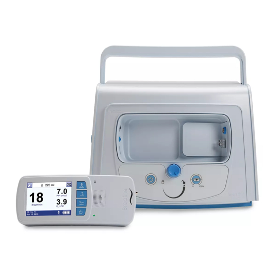
LIFE2000 VENTILATION SYSTEM INTRODUCTION LIFE2000 VENTILATION SYSTEM INTRODUCTION FEATURES PACKAGING CONTENTS WARNING: The Life2000® Ventilation System is a critical care, volume control mechanical ventilation system designed for a For any accessories, read the label and accompanying document(s) before use. broad range of applications in critical care and home settings. TIP: The modular Life2000®... -
Page 8: Life2000 Ventilator Versions
LIFE2000 VENTILATION SYSTEM INTRODUCTION LIFE2000 VENTILATION SYSTEM INTRODUCTION SYSTEM COMPONENTS LIFE2000® VENTILATOR VERSIONS There are two released ventilator versions of the Life2000 Ventilator. You will be able to identify the version of the ventilator based on the REF number. The functionality of the ventilator’s Communication Port, Battery Charge Icon, and System Alarms differ for each version of the ventilator. -
Page 9: Compressor
LIFE2000 VENTILATION SYSTEM INTRODUCTION LIFE2000 VENTILATION SYSTEM INTRODUCTION CONFIGURATIONS COMPRESSOR FRONT The modular Life2000® Ventilation System (system) is composed of the Life2000® Ventilator (ventilator) and the Ventilator docking cradle Life2000® Compressor (compressor). The system can be used in three different configurations. Power source indicator light STATIONARY CONFIGURATION Power button for compressor... -
Page 10: Chapter 2: Stationary Configuration
STATIONARY CONFIGURATION STATIONARY CONFIGURATION INTRODUCTION TO STATIONARY CONFIGURATION POSITIONING AND CARRYING THE COMPRESSOR Position the compressor upright on a flat, level surface. Make sure that the cooling vents, cooling filter cover, and air inlet on the back of the compressor are not blocked, and there is sufficient clearance from surrounding objects. Protect the compressor from falling. -
Page 11: Supplying Power To The Compressor
STATIONARY CONFIGURATION STATIONARY CONFIGURATION SUPPLYING POWER TO THE COMPRESSOR DOCKING THE VENTILATOR INTO THE COMPRESSOR An AC power cord and external power supply are included with the compressor. NOTE: When switching between ventilation system configurations, ensure that the patient receives adequate ventilation therapy;... -
Page 12: Connecting An Interface To The Compressor
STATIONARY CONFIGURATION STATIONARY CONFIGURATION POWERING ON SEQUENCE IN STATIONARY CONFIGURATION Turn the locking knob clockwise to the locked position to lock the ventilator in the compressor. Power on the compressor by pressing the power button for the When the compressor is on, check that the locked icon lights up compressor. -
Page 13: Checking The Compressor's Internal Battery Status
STATIONARY CONFIGURATION STATIONARY CONFIGURATION CHECKING THE COMPRESSOR’S INTERNAL BATTERY STATUS SILENCE ALARM BUTTON ON THE COMPRESSOR The compressor is equipped with an internal battery for temporary AC power disruptions. This internal battery: Silencing and clearing alarms is a multi-step process that depends on alarm priority and how many alarms are active. -
Page 14: Powering Off Sequence In Stationary Configuration
STATIONARY CONFIGURATION EXTENDED RANGE CONFIGURATION POWERING OFF SEQUENCE IN STATIONARY CONFIGURATION INTRODUCTION TO EXTENDED RANGE CONFIGURATION To power off the ventilator, press the ventilator's power button for three seconds until a confirmation screen appears. The Life2000® Ventilation System can be used in different configurations of operation as the patient’s needs change. -
Page 15: Positioning And Carrying The Compressor
EXTENDED RANGE CONFIGURATION EXTENDED RANGE CONFIGURATION POSITIONING AND CARRYING THE COMPRESSOR SUPPLYING POWER TO THE COMPRESSOR Position the compressor upright on a flat, level surface. Make sure that the cooling vents, cooling filter cover, and An AC power cord and external power supply are included with the compressor. air inlet on the back of the compressor are not blocked, and there is sufficient clearance from surrounding objects. -
Page 16: Undocking The Ventilator From The Compressor
EXTENDED RANGE CONFIGURATION EXTENDED RANGE CONFIGURATION UNDOCKING THE VENTILATOR FROM THE COMPRESSOR CONNECTING THE VENTILATOR AND COMPRESSOR IN EXTENDED RANGE CONFIGURATION NOTE: When switching between ventilation system configurations, ensure that the patient receives adequate In this configuration, the ventilator and compressor are connected by an oxygen hose; this allows use of the ventilation therapy;... -
Page 17: Connecting An Interface To The Ventilator In Extended Range Configuration
EXTENDED RANGE CONFIGURATION EXTENDED RANGE CONFIGURATION CONNECTING AN INTERFACE TO THE VENTILATOR IN EXTENDED RANGE THE COMBO ® HOSE CONFIGURATION The CombO ® hose may be used to connect the Life2000® Ventilation System in Extended Range Configuration and provide supplemental low-flow oxygen from an oxygen concentrator or other low-flow oxygen source. Plug the Breathe Pillows Entrainment Interface or Universal Circuit ®... -
Page 18: Connecting A Low-Flow Oxygen Source Using The Combo2® Hose
EXTENDED RANGE CONFIGURATION EXTENDED RANGE CONFIGURATION CONNECTING TO A LOW-FLOW OXYGEN SOURCE USING THE COMBO ® HOSE POWERING ON SEQUENCE IN EXTENDED RANGE CONFIGURATION 100% Power on the compressor by pressing the power button for the compressor. When powered on, lights surrounding the compressor power button will illuminate: WARNING: The interface, source gas supply hose, and power cords should be positioned to avoid restricting movement, Green indicates the compressor is connected to AC power. -
Page 19: Checking The Compressor's Internal Battery Status
EXTENDED RANGE CONFIGURATION EXTENDED RANGE CONFIGURATION CHECKING THE COMPRESSOR’S INTERNAL BATTERY STATUS ASSEMBLING THE VENTILATOR BATTERY CHARGER AND CHARGING THE VENTILATOR The compressor is equipped with an internal battery for temporary AC power disruptions. This internal battery: • charges when the compressor is attached to AC power. AC power cord Battery charger •... -
Page 20: Securing The Ventilator
EXTENDED RANGE CONFIGURATION EXTENDED RANGE CONFIGURATION SECURING THE VENTILATOR VENTILATOR SILENCE ALARM BUTTON Silencing and clearing alarms is a multi-step process that depends on alarm priority and how many alarms are BELT CLIP active. For more information see "Chapter 7: Alarms, Alerts, and Troubleshooting". You can attach the ventilator to a belt or waistband using the included belt clip. -
Page 21: Powering Off Sequence In Extended Range Configuration
EXTENDED RANGE CONFIGURATION STAND-ALONE CONFIGURATION POWERING OFF SEQUENCE IN EXTENDED RANGE CONFIGURATION INTRODUCTION TO STAND-ALONE CONFIGURATION To power off the ventilator, press the ventilator's power button for three seconds until a confirmation screen appears. The ventilator requires a pressure source for operation. In Stationary Configuration and Extended Range 100% Configuration, the compressor is the pressure source. -
Page 22: Testing The Ventilator
STAND-ALONE CONFIGURATION STAND-ALONE CONFIGURATION TESTING THE VENTILATOR CONNECTING TO A CYLINDER In a multi-patient setting, the ventilator must be tested before it is assigned to a new patient. For instructions on An oxygen regulator is required to connect the ventilator to an oxygen cylinder. Ensure that the oxygen regulator testing the ventilator, see "Testing Ventilator Alarms"... -
Page 23: Connecting An Interface To The Ventilator In Stand-Alone Configuration
STAND-ALONE CONFIGURATION STAND-ALONE CONFIGURATION CONNECTING AN INTERFACE TO THE VENTILATOR Oxygen Choose the appropriate length approved IN STAND-ALONE CONFIGURATION oxygen hose for your needs. regulator A six-foot oxygen hose is included. Plug the Breathe Pillows Entrainment Interface or Universal Circuit Connector For information about ordering accessories ®... -
Page 24: Assembling The Ventilator Battery Charger And Charging The Ventilator
STAND-ALONE CONFIGURATION STAND-ALONE CONFIGURATION SECURING THE VENTILATOR ASSEMBLING THE VENTILATOR BATTERY CHARGER AND CHARGING THE VENTILATOR BELT CLIP You can attach the ventilator to a belt or waistband using the included belt clip. The ventilator can be worn on AC power cord Battery charger either the right or left side. -
Page 25: Pole Mount
STAND-ALONE CONFIGURATION STAND-ALONE CONFIGURATION VENTILATOR SILENCE ALARM BUTTON POLE MOUNT You can attach the ventilator to a pole using an optional pole mount. For information about ordering accessories and replacement parts, see "Accessories and Replacement Parts" on page 147. Silencing and clearing alarms is a multi-step process that depends on alarm priority and how many alarms are active. -
Page 26: Chapter 5: Connecting An Interface
Hillrom ™ ventilator or compressor. to be cleaned or sterilized prior to first use. The Breathe Pillows Entrainment Interface is a non-invasive patient mask that connects directly to a Hillrom ™ ventilator or compressor. - Page 27 CONNECTING AN INTERFACE CONNECTING AN INTERFACE CONNECTING THE UNIVERSAL CIRCUIT® CONNECTOR EXAMPLES OF PATIENT MASK AND TUBE CONNECTIONS TO THE OXYGEN ADAPTER AND PATIENT MASK OR TUBE The Universal Circuit Connector The Universal Circuit Connector with The Universal Circuit Connector ®...
- Page 28 CONNECTING AN INTERFACE CONNECTING AN INTERFACE BREATHE PILLOWS ENTRAINMENT INTERFACE WEARING THE BREATHE PILLOWS ENTRAINMENT INTERFACE Place the interface in front of the patient with the curve of the Interface Before using the Breathe Pillows Entrainment Interface, visually inspect it for damage. towards the patient’s face and the entrainment ports facing up.
- Page 29 VENTILATION SETTINGS VENTILATION SETTINGS INTRODUCTION TO VENTILATION SETTINGS MOVING BETWEEN THE HOME SCREEN AND MENU SCREEN Touch the Wrench Button to go to the Menu Screen. 500 ml All of the clinical and utility menus can be accessed, viewed, and edited by the touch screen on the ventilator. 20.0 To use the touch screen, simply touch a button or an area of the screen you want to make active.
- Page 30 VENTILATION SETTINGS VENTILATION SETTINGS DEFINING CLINICAL SETTINGS DISABLING ACCESS TO THE CLINICIAN’S SETTINGS MENU There are two ways to disable access to the Clinician’s Settings menu to prevent unintended changes to the programmed clinical settings. NOTE: For facilities where trained healthcare professionals are the intended users, the password to access clinical settings may be enabled or disabled.
- Page 31 VENTILATION SETTINGS VENTILATION SETTINGS PRESCRIPTION SETTINGS ACTIVATING PRESCRIPTION SETTINGS Each icon on the Prescription Settings screen represents a prescription. Prescription Settings Each Activity Icon on a button in the Prescription Settings screen represents a prescription that can be Check the box below a Prescription Setting button to make the programmed by a clinician and made available to the patient.
- Page 32 VENTILATION SETTINGS VENTILATION SETTINGS BREATH TYPES FACTORY DEFAULT PRESCRIPTION SETTINGS The following table lists the Life2000® factory default Prescription Settings that may be edited. For a full list of factory defaults, see the "Summary of Factory Default Settings" on page 77. There are two breath types that apply to the Volume Control ventilation provided by the ventilation system: •...
- Page 33 VENTILATION SETTINGS VENTILATION SETTINGS SETTING VENTILATION PARAMETERS IN CONTROL VENTILATION MODE To set a Prescription Setting for Control Ventilation Mode, the following parameters need to be set according to the table below: In this mode, the ventilation system delivers volume control therapy only for mandatory breaths. A mandatory breath is delivered according to the breath setting (BPM).
- Page 34 VENTILATION SETTINGS VENTILATION SETTINGS SETTING VENTILATION PARAMETERS IN ASSIST/CONTROL VENTILATION MODE To set a Prescription Setting for Assist/Control ventilation mode, the following parameters need to be set according to the table below: In this mode, the ventilation system provides Tidal Volume during inhalation for assisted and mandatory breaths. An assisted breath is started when there is patient effort, but it is ended when the Inspiratory Time setting has been met.
- Page 35 VENTILATION SETTINGS VENTILATION SETTINGS SETTING VENTILATION PARAMETERS IN ASSIST VENTILATION MODE To set a Prescription Setting for Assist ventilation mode, the following parameters need to be set according to the table below: In this mode, the ventilation system provides Tidal Volume during inhalation for assisted breaths. An assisted breath is started when there is patient effort and is ended when the Inspiratory Time setting has been met.
- Page 36 VENTILATION SETTINGS VENTILATION SETTINGS VENTILATION SETTINGS SUMMARY SETTING ALARM LIMITS FOR BREATH RATE AND PIP PARAMETER MINIMUM MAXIMUM INCREMENT To view or edit critical alarms, access the Alarm Limits screen from the Clinician’s Settings screen. Volume (ml) Clinician’s Settings On the Clinician’s Setting screen, touch Alarm Limits. I-Time (sec) 0.15 3.00...
- Page 37 VENTILATION SETTINGS VENTILATION SETTINGS SETTING BREATH TIMEOUT (APNEA BACKUP VENTILATION MODE) SELECTING THE SOURCE GAS The Life2000® Ventilation System uses Air as the factory set default source gas. If using an oxygen cylinder, select O as the Source Gas. Clinician’s Settings On the Clinician’s Setting screen, touch Breath Timeout.
-
Page 38: This Prescription Setting Is Not Active" Message
VENTILATION SETTINGS VENTILATION SETTINGS CHOOSING AN ACTIVITY BUTTON (PATIENT SELECTABLE) TO BEGIN VENTILATION “INCOMPATIBLE SETTINGS” MESSAGE If the selected Activity Button represents a prescription that is not available, this When the ventilator is first powered on, you must select an Activity Button to begin ventilation. The three Activity message will appear on the touch screen. -
Page 39: Adjusting The Trigger Sensitivity (Patient-Adjustable)
VENTILATION SETTINGS VENTILATION SETTINGS ADJUSTING THE TRIGGER SENSITIVITY (PATIENT ADJUSTABLE) CHANGING TRIGGER SENSITIVITY While ventilating, on the Trigger Sensitivity screen, touch the Up arrow to Trigger sensitivity determines how easily a patient’s inspiratory effort triggers the breath delivery. For shallow increase the value or the Down arrow to decrease it. -
Page 40: Accessing The Utilities Menu
VENTILATION SETTINGS VENTILATION SETTINGS ACCESSING THE UTILITIES MENU SETTING TIME AND DATE On the Utilities Menu screen, touch Set Time/Date. With the Utilities menu, you can change the time and date, brightness of the touch screen, volume of audible alarms, and set alarms to vibrate mode. On any screen, touch the Wrench button. -
Page 41: Setting Vibration Mode
VENTILATION SETTINGS VENTILATION SETTINGS SETTING VIBRATION MODE SETTING AUDIO LOUDNESS The Set Vibration screen lets you change alarm notifications from audible tones to a vibration. However, if a low- WARNING: Ensure that the alarm loudness is set above the loudness of your surroundings. or medium-priority vibrating alarm occurs and is not resolved in 60 seconds, an audible alarm occurs. -
Page 42: Adjusting Screen Brightness
VENTILATION SETTINGS VENTILATION SETTINGS ADJUSTING SCREEN BRIGHTNESS VIEWING SOFTWARE VERSION INFORMATION The Information screen displays information about the ventilator and its operation. On the Utilities Menu screen, touch Set Brightness. On any screen, touch the Wrench button. 500 ml 20.0 PIP cmH Breath/min 10:11a, Fri... -
Page 43: Summary Of Factory Default Settings
VENTILATION SETTINGS ALARMS, ALERTS, AND TROUBLESHOOTING SUMMARY OF FACTORY DEFAULT SETTINGS INTRODUCTION TO ALARMS AND ALERTS The following table lists the factory default settings for the ventilator. WARNING: • If the Life2000® Ventilation System is not functioning properly, respiratory therapy may be compromised DEFAULT VALUE and may result in patient harm or death. -
Page 44: Chapter 7: Alarms, Alerts, And Troubleshooting
ALARMS, ALERTS, AND TROUBLESHOOTING ALARMS, ALERTS, AND TROUBLESHOOTING VENTILATOR ON-SCREEN ALARM SOUNDS AND MESSAGE DISPLAY SILENCING AND CLEARING ON-SCREEN ALARMS When an alarm notification occurs there is a distinct sound and a display message corresponding to the priority Alarm notifications that appear on the touch screen originate from the ventilator. Silencing and clearing on-screen level of the alarm. - Page 45 ALARMS, ALERTS, AND TROUBLESHOOTING ALARMS, ALERTS, AND TROUBLESHOOTING VENTILATOR ALARMS NOTES: The following tables list high-, medium-, and low-priority alarms. For each alarm, the tables list the notification, the • Options for resolving the alarm are based on the configuration of the ventilation system. possible causes for the alarm, and possible options for resolving it.
-
Page 46: Chapter 7: Alarms, Alerts, And Troubleshooting
ALARMS, ALERTS, AND TROUBLESHOOTING ALARMS, ALERTS, AND TROUBLESHOOTING HIGH-PRIORITY ALARMS (CONTINUED) CHECKS AND POSSIBLE RESOLUTION IN EACH CONFIGURATION NOTIFICATION CAUSE STAND-ALONE CONFIGURATION EXTENDED RANGE CONFIGURATION STATIONARY CONFIGURATION Low Gas Pressure Gas pressure drops below the Check all connections for possible leak. Verify that the compressor is powered on. -
Page 47: Medium-Priority Alarms
ALARMS, ALERTS, AND TROUBLESHOOTING ALARMS, ALERTS, AND TROUBLESHOOTING HIGH-PRIORITY ALARMS (CONTINUED) CHECKS AND POSSIBLE RESOLUTION IN EACH CONFIGURATION NOTIFICATION CAUSE STAND-ALONE CONFIGURATION EXTENDED RANGE CONFIGURATION STATIONARY CONFIGURATION Very Low Battery Ventilator battery capacity drops Connect the ventilator to the ventilator battery Connect the ventilator to the ventilator battery Ensure the ventilator is properly docked and locked into the below 15%... - Page 48 ALARMS, ALERTS, AND TROUBLESHOOTING ALARMS, ALERTS, AND TROUBLESHOOTING MEDIUM-PRIORITY ALARMS (CONTINUED) CHECKS AND POSSIBLE RESOLUTION IN EACH CONFIGURATION NOTIFICATION CAUSE STAND-ALONE CONFIGURATION EXTENDED RANGE CONFIGURATION STATIONARY CONFIGURATION Breath Timeout No breath is detected for 20 or Patient is not breathing. Patient is not breathing.
- Page 49 ALARMS, ALERTS, AND TROUBLESHOOTING ALARMS, ALERTS, AND TROUBLESHOOTING MEDIUM-PRIORITY ALARMS (CONTINUED) CHECKS AND POSSIBLE RESOLUTION IN EACH CONFIGURATION NOTIFICATION CAUSE STAND-ALONE CONFIGURATION EXTENDED RANGE CONFIGURATION STATIONARY CONFIGURATION Low Del. Pressure Interface pressure during delivery Check the interface connections. Check that the interface is connected to the Ensure the ventilator is properly docked into the (Low Delivery Pressure) fails to exceed the minimum...
-
Page 50: Low-Priority Alarms
ALARMS, ALERTS, AND TROUBLESHOOTING ALARMS, ALERTS, AND TROUBLESHOOTING LOW-PRIORITY ALARMS CHECKS AND POSSIBLE RESOLUTION IN EACH CONFIGURATION NOTIFICATION CAUSE STAND-ALONE CONFIGURATION STATIONARY CONFIGURATION EXTENDED RANGE CONFIGURATION Excessive Leak An excessive leak is present Ensure patient interface or mask is positioned to Ensure patient interface or mask is positioned to Ensure patient interface or mask is positioned to ensure a ensure a proper seal. -
Page 51: Compressor Alerts
ALARMS, ALERTS, AND TROUBLESHOOTING ALARMS, ALERTS, AND TROUBLESHOOTING COMPRESSOR ALERTS NOTES: The compressor has alerts that are independent of the ventilator. Compressor alerts must be resolved in order for • Options for resolving the alert are based on the configuration of the ventilation system. the compressor alert notifications to be silenced;... -
Page 52: Troubleshooting
ALARMS, ALERTS, AND TROUBLESHOOTING ALARMS, ALERTS, AND TROUBLESHOOTING TROUBLESHOOTING • Options for resolving the situation are based on the configuration of the ventilation system. The following table lists situations that may occur during normal use of the ventilation system that do not have an •... - Page 53 ALARMS, ALERTS, AND TROUBLESHOOTING ALARMS, ALERTS, AND TROUBLESHOOTING ADDITIONAL TROUBLESHOOTING SITUATIONS (CONTINUED) CHECKS AND POSSIBLE RESOLUTION IN EACH CONFIGURATION NOTIFICATION CAUSE STAND-ALONE CONFIGURATION STATIONARY CONFIGURATION EXTENDED RANGE CONFIGURATION Breath indicator light is Ventilator is not on. Ensure ventilator is on. Ensure ventilator is on.
- Page 54 ALARMS, ALERTS, AND TROUBLESHOOTING ALARMS, ALERTS, AND TROUBLESHOOTING ADDITIONAL TROUBLESHOOTING SITUATIONS (CONTINUED) CHECKS AND POSSIBLE RESOLUTION IN EACH CONFIGURATION NOTIFICATION CAUSE STAND-ALONE CONFIGURATION STATIONARY CONFIGURATION EXTENDED RANGE CONFIGURATION An on-screen alarm Low gas pressure The cylinder is nearly empty; connect the ventilator Contact your service representative.
- Page 55 ALARMS, ALERTS, AND TROUBLESHOOTING ALARMS, ALERTS, AND TROUBLESHOOTING ADDITIONAL TROUBLESHOOTING SITUATIONS (CONTINUED) CHECKS AND POSSIBLE RESOLUTION IN EACH CONFIGURATION NOTIFICATION CAUSE STAND-ALONE CONFIGURATION STATIONARY CONFIGURATION EXTENDED RANGE CONFIGURATION Negative PIP value is Low PIP When using the Life2000® Ventilator interfaced When using the Life2000®...
-
Page 56: Chapter 8: Maintenance
MAINTENANCE MAINTENANCE CLEANING BEFORE FIRST USE ALARM CHECKS Confirm that when the ventilator is powered on, it makes audible tones. If tones are not heard, the ventilator It is not necessary to clean or sterilize the Life2000® Ventilation System before the first use. should be returned to your service representative. -
Page 57: Cleaning For Single Patient Use
MAINTENANCE MAINTENANCE CLEANING FOR SINGLE PATIENT USE CLEANING FOR MULTI-PATIENT USE VENTILATION SYSTEM WARNING: To prevent risk of cross-contamination, clean and disinfect the ventilation system before using it on a new Once a week, or more often if necessary, follow the instructions found in the “Cleaning and Disinfecting the patient, and use a new Breathe Pillows Entrainment Interface or Universal Circuit Connector. -
Page 58: Cleaning The Breathe Interfaces
MAINTENANCE MAINTENANCE CLEANING THE BREATHE INTERFACES PURGING THE UNIVERSAL CIRCUIT CONNECTOR ® After cleaning and completely drying the interface or when you suspect dust or debris has entered the airflow passage, purge the interface with the purge tube connector and purge tube. NOTE: Below instructions are for cleaning Breathe interfaces. -
Page 59: Purging The Breathe Pillows Entrainment Interface
MAINTENANCE MAINTENANCE PURGING THE BREATHE PILLOWS ENTRAINMENT INTERFACE Firmly press the smaller end of the purge tube over the oxygen tubing connection on the interface. Power off the compressor. Twist to remove the purge tube from the purge tube connector. Place the patient on an alternate means of ventilation, if necessary. -
Page 60: Preventive Maintenance
MAINTENANCE MAINTENANCE CHECKING AND REPLACING THE CONDENSATION TRAY PREVENTIVE MAINTENANCE The condensation tray collects water condensate from humidity in the air. WARNING: Unauthorized modifications can result in equipment damage, or patient injury or death. Check the condensation tray daily, or more frequently if needed. The frequency that the condensation tray needs CAUTION: to be checked and emptied will depend on the amount of humidity in the ambient air. -
Page 61: Checking And Replacing The Air Inlet Filter
MAINTENANCE MAINTENANCE CHECKING AND REPLACING THE AIR INLET FILTER CHECKING AND REPLACING THE COOLING FILTER ASSEMBLY The air inlet filter is used to filter ambient air entering through the back of the compressor. The cooling filter is used to filter air that enters the compressor to cool it during operation. The compressor air inlet filter needs to be changed every three to six months, or as needed. - Page 62 MAINTENANCE MAINTENANCE TESTING VENTILATOR ALARMS TESTING ALARM CONDITIONS Do not test while the ventilator is being used on a patient. This section gives instructions for testing ventilator alarms. Procedures described in this section are only to be performed by trained personnel. NOTE: These testing procedures require clinical settings to be changed.
- Page 63 MAINTENANCE MAINTENANCE TESTING SETUP 2. TESTING THE LOW GAS PRESSURE ALARM (MEDIUM PRIORITY) Undock the ventilator from the compressor. For more information, see "Undocking the Ventilator from the Begin by ventilating using the Low Activity button. Allow the ventilator to ventilate for a few breaths using the Compressor"...
- Page 64 MAINTENANCE MAINTENANCE 4. TESTING THE LOW PIP PRESSURE ALARM (MEDIUM PRIORITY) AND 5. TESTING THE HIGH PIP PRESSURE ALARM (HIGH PRIORITY) LOW DELIVERY PRESSURE ALARM (MEDIUM PRIORITY) Begin by ventilating using the Low Activity button. Allow the ventilator to ventilate for a few breaths using the current settings.
- Page 65 MAINTENANCE MAINTENANCE 7. TESTING THE HIGH BREATH RATE ALARM (MEDIUM PRIORITY) 6. TESTING THE BREATH TIMEOUT ALARM (MEDIUM PRIORITY) AND HIGH CIRCUIT PRESSURE ALARM (HIGH PRIORITY) Begin by ventilating using the Low Activity button. Allow the ventilator to ventilate for a few breaths using the Ventilation Settings Begin by ventilating using the Low Activity button.
- Page 66 MAINTENANCE MAINTENANCE 8. TESTING THE LOW BREATH RATE ALARM (MEDIUM PRIORITY) 9. TESTING THE BATTERY LOW ALARM (MEDIUM-PRIORITY) AND VERY LOW BATTERY ALARM (HIGH-PRIORITY) Begin by ventilating using the Low Activity button. Allow the ventilator to ventilate for a few breaths using the current settings.
- Page 67 BATTERY INFORMATION BATTERY INFORMATION BATTERY INFORMATION BATTERY INFORMATION The Life2000® Ventilation System uses lithium ion batteries with the following specifications. CHECKING THE VENTILATOR BATTERY CHARGE Ensure that the ventilator is powered on. VENTILATOR BATTERY SPECIFICATIONS Check the Ventilator Battery Charge icon on the touch screen to see SPECIFICATION DESCRIPTION the current battery charge level for the ventilator.
- Page 68 BATTERY INFORMATION BATTERY INFORMATION VENTILATOR BATTERY CHARGER AND POWER CORD SPECIFICATIONS WHEN THE COMPRESSOR IS CONNECTED TO AC POWER When the compressor is powered on and connected to AC power, the indicator lights surrounding the compressor’s power button are illuminated in green. VENTILATOR BATTERY CHARGER SPECIFICATIONS TIP: CATEGORY...
- Page 69 SPECIFICATIONS SPECIFICATIONS OXYGEN MONITOR VENTILATOR ALTITUDE VOLUME ADJUSTMENT TABLE The volume output by the ventilator is not automatically adjusted for altitude. The following table shows the WARNING: typical calculated volume output for several volume settings at different altitudes. Check the performance of the To ensure accuracy of oxygen administration and to monitor for the presence of contamination (incorrect gas ventilator for adequate therapy delivery in the environment(s) in which it will be used and adjust the volume to connected), use an external oxygen monitor to verify the oxygen concentration in the delivered gas.
- Page 70 SPECIFICATIONS SPECIFICATIONS The Life2000® Ventilator is classified per IEC 60601-1 as portable, Class II, Type BF, Drip-proof (IPX1), continuous PARAMETER DESCRIPTION operation. Means of initiating and Control ventilation mode: The inspiratory phase is started and terminated by the The Life2000® Compressor is classified per IEC 60601-1 as portable, Class II, continuous operation. terminating inspiratory ventilator based on set inspiratory time and respiratory rate.
- Page 71 SPECIFICATIONS SPECIFICATIONS PARAMETER DESCRIPTION PARAMETER DESCRIPTION Range: 0 LPM to 20 LPM. Ventilator Alarms Resolution: 0.1 LPM. High Circuit Pressure Interface may be pinched or kinked. Accuracy: ±10% or ±(10 ml x average breath rate), whichever is greater. Range, resolution, and High PEEP Pressure Interface may be blocked.
- Page 72 SPECIFICATIONS SPECIFICATIONS PARAMETER DESCRIPTION PARAMETER DESCRIPTION Ventilator AC Battery Charger Specifications Storage and Transport Environment Input AC voltage 100-240 VAC Storage & Transport -20°C to +60°C (-4°F to +140°F) Temperature Input AC frequency 50-60 Hz Storage & Transport Input AC current 0.3 A max.
- Page 73 PRINCIPLES OF OPERATION PRINCIPLES OF OPERATION GENERAL OVERVIEW Outlet Fitting The Life2000® Ventilation System utilizes an electromechanical pneumatic system under the control of a microprocessor to deliver patient ventilation. The following descriptions and diagrams illustrate the major components of the ventilation system in each configuration. Source Gas Supply Hose STATIONARY CONFIGURATION OPERATION SUMMARY AND PNEUMATIC DIAGRAM...
- Page 74 COMPLIANCE AND IEC CLASSIFICATION COMPLIANCE AND IEC CLASSIFICATION IEC COMPLIANCE: EN/IEC 60601-1-2 4th edition: 2014 (Medical electrical equipment Part 1-2: General GUIDANCE AND MANUFACTURER’S DECLARATION: ELECTROMAGNETIC IMMUNITY requirements for basic safety and essential requirements - Collateral standard: Electromagnetic disturbances The Life2000® Ventilation System is intended for use in the electromagnetic environment specified below. The - Requirements and tests) defines the RF emissions limits and minimum RF immunity requirements for different customer or user of the ventilation system should ensure that it is used in such an environment.
- Page 75 COMPLIANCE AND IEC CLASSIFICATION COMPLIANCE AND IEC CLASSIFICATION GUIDANCE AND MANUFACTURER’S DECLARATION: ELECTROMAGNETIC IMMUNITY RECOMMENDED SEPARATION DISTANCES BETWEEN PORTABLE AND MOBILE RF COMMUNICATION The Life2000® Ventilation System is intended for use in the electromagnetic environment specified below. The EQUIPMENT AND THE LIFE2000® VENTILATION SYSTEM customer or user of the ventilation system should ensure that it is used in such an environment.
- Page 76 ICONS ICONS ICON WHERE USED MEANING ICON WHERE USED MEANING Ventilator Indicates communication port. This port is only used by the manufacturer. Ventilator touch Displayed on touch screen if ventilator battery status is unknown or charge is screen critically low (< 5%). Ventilator Indicates power-in port.
- Page 77 ICONS ICONS ICON WHERE USED MEANING ICON WHERE USED MEANING Ventilator label, Indicates disposal of device must conform to WEEE Directive (Waste in Compressor Indicates compliance with RoHS. compressor label, Electrical and Electronic Equipment) 2011/65/EU. external power compressor external supply power supply Compressor Indicates the unlocking knob is in the unlocked position.
- Page 78 APPENDIX APPENDIX APPENDIX ACCESSORIES AND REPLACEMENT PARTS CYLINDER DURATION INFORMATION The duration of compressed medical oxygen cylinders depends on the volume of the cylinder and the breathing WARNING: For any accessories, read the label and accompanying document(s) before use. pattern of each patient, which can change throughout the day. Observe your daily oxygen consumption a few times before estimating typical use.
- Page 79 APPENDIX APPENDIX APPENDIX APPENDIX POTENTIAL TIDAL VOLUMES For other cylinder sizes, use the following gas usage chart to estimate your cylinder duration. OXYGEN USAGE (LPM) TABLE The potential tidal volumes for the corresponding set volumes on the Life2000 Ventilator are shown in the ®...
- Page 80 APPENDIX: FiO TABLES APPENDIX: FiO TABLES UNIVERSAL CIRCUIT® CONNECTOR USING AIR AS THE PRESSURE SOURCE* BREATHE PILLOWS ENTRAINMENT INTERFACE USING AIR AS THE PRESSURE SOURCE* based on 0.9 sec iTime based on 0.9 sec iTime BREATHE PILLOWS ENTRAINMENT INTERFACE USING OXYGEN AS THE PRESSURE SOURCE* UNIVERSAL CIRCUIT®...
- Page 81 Breathe Technologies, Inc., a Hillrom Company, warrants that the Life2000® ventilators and compressors will be free from persons to whom it is directly transmitted by Breathe Technologies, Inc, a Hillrom Company. No part of this manual ™ defects in material and workmanship for a period of one (1) year from the date of shipment. Products that are repaired or...
- Page 82 Hillrom Technical Support & Customer Service ™ 1020 West County Road F 800-426-4224 St. Paul, MN 55126 PL-20-0028 Rev F ©2020. Breathe, Breathe Technologies, CombO , Life2000, and Universal Circuit are trademarks of Breathe Technologies, Inc., a Hillrom Company...
Need help?
Do you have a question about the Breathe LIFE2000 and is the answer not in the manual?
Questions and answers