Table of Contents
Advertisement
Quick Links
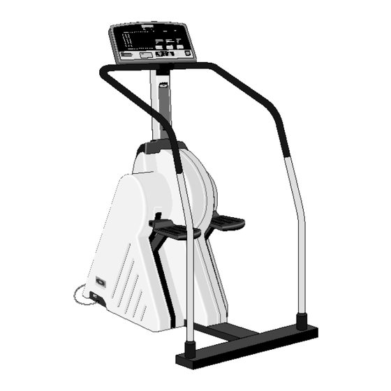
C762, C764, C764i Stairclimber
C762, C764, C764i Stairclimber
Warning: This service manual is for use by Precor trained service providers only.
If you are not a Precor Trained Servicer, you must not attempt to service any Precor Product;
Call your dealer for service.
This document contains information required to perform the majority of troubleshooting, and
replacement procedures required to repair and maintain this product.
This document contains general product information, software diagnostic procedures (when
available), preventative maintenance procedures, inspection and adjustment procedures,
troubleshooting procedures, replacement procedures and electrical block and wiring diagrams.
To move directly to a procedure, click the appropriate procedure in the bookmark section to the
left of this page. You may "drag" the separator bar between this page and the bookmark section
to change the size of the page being viewed.
© 2004 Precor Incorporated
Unauthorized Reproduction and Distribution Prohibited By Law
20039-105
Page 1
Advertisement
Table of Contents

Related Manuals for Precor C762


Summary of Contents for Precor C762
- Page 1 C762, C764, C764i Stairclimber Warning: This service manual is for use by Precor trained service providers only. If you are not a Precor Trained Servicer, you must not attempt to service any Precor Product; Call your dealer for service. This document contains information required to perform the majority of troubleshooting, and replacement procedures required to repair and maintain this product.
-
Page 2: Section One - Things You Should Know
Section One, Things You Should Know. This section includes warning and caution statements, safety guidelines, and a list of required tools and equipment. It is highly recommended that you read this section, as well as the C764/C762 Climber Owner’s Manual, before performing the maintenance procedures provided in this manual. -
Page 3: Miscellaneous Information
Use anti-static handling procedures and wear an anti-static device (such as a wrist strap) when you perform this procedure. Anti-static kits can be ordered from Precor Customer Service (Precor part number 20024-101). - Page 4 C762, C764, C764i Stairclimber Version A and Version B Disk Assemblies Diagram 1-2 shows the Version A and Version B disk assembly shafts. The Version B disk assembly shaft has shoulders, the Version A disk assembly shaft does not. The Version A and Version B disk assemblies are interchangeable.
-
Page 5: Warning, Caution Statements And Safety Guidelines
C762, C764, C764i Stairclimber Warning, Caution Statements and Safety Guidelines WARNING and Caution statements are used throughout this manual to protect both you and the C760 Series Climber. Additional precautions and guidelines are provided to ensure your safety when servicing an C760 Series Climber. - Page 6 C762, C764, C764i Stairclimber • Be aware that the weight limit for the C760 Series Climber is 350 pounds. • Keep all electrical components, such as the power cord and the ON/OFF switch, away from water and other liquids. Page 6...
-
Page 7: Required Tools And Equipment
C762, C764, C764i Stairclimber Required Tools and Equipment The following list is a summary of the tools and equipment required by the procedures in this manual. We recommend that you have this equipment available when you service C760 Series Climbers. - Page 8 C762, C764, C764i Stairclimber Eddy Current Resistance and the C760 Series Climber Magnetism When the disk rotates, it “cuts” the lines of force that make up the magnetic field. As the lines of force are cut, voltage is induced in the disk. The current produced by this induced voltage is called eddy current.
-
Page 9: Procedure 2.1 - Determining Software Version And Total Floors Climbed
Diagram 2.1 and the C764 display is shown in Diagram 2.2 On units manufactured after May 28, 2000, press keys RESET, 6,5, sequentially. The C762 display is shown in Diagram 2.1 and the C764 display is shown in Diagram 2.2 The version number of the PROM is displayed in the upper right alpha-numeric display. - Page 10 C762, C764, C764i Stairclimber Diagram 2.1 - C762 Stairclimber Display Key #2 Key #3 Key #1 Key #5 Key #7 Key #6 Diagram 2.2 - C764 Stairclimber Display Key #2 Key #1 Key #3 Key #5 Key #7 Key #6...
-
Page 11: Procedure 2.2 - Performing Keypad And Display Diagnostics
On units manufactured after may 28, 2000, press keys RESET, 5,1,7,6,5,7,6,1, sequentially. The C762 display is shown in Diagram 2.1 and the C764 display is shown in Diagram 2.2. Watch the electronic console as the display test progresses. This test is programmed to display the following LED illumination sequences: A vertical line and then a horizontal line scrolls across the left LED matrix. - Page 12 C762, C764, C764i Stairclimber THEN... OTHERWISE... The keypad test is successful; continue Go to Step 3 of Procedure 6.2. with the next step. Press RESET. The message KEY PRESSED PLEASE WAIT is momentarily displayed on the electronic console. When the PRESS ENTER FOR PROGRAMS prompt is displayed, continue with the next step.+...
-
Page 13: Procedure 2.3 - Selecting Club Settings
[M/DN FT/UP] prompt is displayed. On units manufactured after may 28, 2000, press keys RESET, 5,6,5,1,5,6,5, sequentially. The C762 display is shown in Diagram 2.1 and the C764 display is shown in Diagram 2.2. Press the WORK LEVEL key to select U. S. Standard units. Press the WORK LEVEL key to select the Metric measurement system. -
Page 14: Procedure 2.4 - Documenting Software Problems
When a problem is found with either the software or upper or lower PCA’s, record the information listed below. If you isolate the problem to either the PROM, upper PCA, or lower PCA, include the information you recorded with the malfunctioning PROM or PCA when you ship it to Precor Customer Service. -
Page 15: Section Three - Preventive Maintenance
Regular Preventive Maintenance (Owner) Cleanliness of the C760 Series Climbers and their operating environment will keep maintenance problems and service calls to a minimum. For this reason, Precor recommends that the following preventive maintenance schedule be followed. At the End of Each Day •... - Page 16 C762, C764, C764i Stairclimber • Check the LEDs mounted on the upper PCA and the function keys displayed on the electronic console by performing Procedure 2.2. • Measure the gaps between the disk and the magnet assemblies as described in Procedure 5.1.
- Page 17 C762, C764, C764i Stairclimber Section Four - Checking Unit Operation This section provides you with a method of checking climber operation. Check climber operation at the end of a maintenance procedure and when it is necessary to ensure that the climber is operating properly.
- Page 18 C762, C764, C764i Stairclimber If the climber resistance does not change or the climber operation feels inconsistent compared with Work Levels 1 and 5... THEN... OTHERWISE... Refer to Section 6. Continue with the next step. 10. Check the LEDs mounted on the upper PCA and the function keys displayed on the electronic console by performing Procedure 2.2.
- Page 19 C762, C764, C764i Stairclimber Procedure 5.1 - Inspecting and Adjusting the Gaps Between the Disk and the Magnet Assemblies Procedure Remove the covers as described in Procedure 7.1. WARNING Before performing maintenance operations with the covers removed, review the Warning and Caution statements listed in Section One, Things You Should Know.
- Page 20 C762, C764, C764i Stairclimber If the .050 feeler gauge does not fit snugly... THEN... OTHERWISE... Continue with the next step. Skip to Step 7. Barely loosen the bolts, lock washers, and flat washers that secure the right magnet assembly to the climber frame (see Diagram 5.2).
- Page 21 C762, C764, C764i Stairclimber along the adjustment slots, the assembly must stay in place after it is moved. Slide the top part of the magnet assembly along its adjustment slot until the .050 feeler gauge fits snugly between the disk and the top coil on the assembly.
- Page 22 C762, C764, C764i Stairclimber Procedure 5.2 - Measuring the Resistance of the Magnet Assemblies Caution Remove power from the climber before you measure magnet resistance. Procedure Remove the covers as described in Procedure 7.1. WARNING Before performing maintenance operations with the covers removed, review the Warning and Caution statements listed in Section One, Things You Should Know.
- Page 23 C762, C764, C764i Stairclimber Diagram 5.3 - Magnet Wiring Page 23...
- Page 24 C762, C764, C764i Stairclimber Procedure 6.1 - Troubleshooting the Lower and Upper Ribbon Cables Fault Isolating the Lower Ribbon Cable Turn off the climber with the circuit breaker, then unplug the power cord from the wall outlet. WARNING Before continuing with this procedure, review the Warning and Caution statements listed in Section Nothings you Should Know.
- Page 25 C762, C764, C764i Stairclimber Diagram 6.1 - Upper and Lower Ribbon cables 12. Disconnect the ribbon cable from the upper PCA. 13. Connect the spare ribbon cable between the upper PCA and the lower ribbon cable connector. 14. Connect the original lower ribbon cable to the lower PCA.
- Page 26 C762, C764, C764i Stairclimber THEN... OTHERWISE... The original upper ribbon cable is The original upper ribbon cable is not bad; install a new cable as described bad; continue with the next step. in Procedure 7.10. 18. Support the display housing while you connect the original upper ribbon cable to the upper PCA.
-
Page 27: Procedure 6.2 - Troubleshooting The Keypad And Upper Pca
C762, C764, C764i Stairclimber Procedure 6.2 - Troubleshooting the Keypad and Upper PCA If the function keys on the electronic console are unresponsive, the problem may be either the upper PCA or keypad. This troubleshooting procedure gives you the information you need to determine which of these components is malfunctioning. - Page 28 C762, C764, C764i Stairclimber Diagram 6.3 - Upper PCA Component Layout Table 6.1 - Voltage Test Points (Function Keys Not Pressed) PLACE THE POSITIVE LEAD OF THE THE VOLTMETER SHOULD VOLTMETER ON... READ... 5 Vdc ± 500 mVdc Pin 1 of J4 5 Vdc ±...
- Page 29 C762, C764, C764i Stairclimber If the voltage readings in Table 6.1 are incorrect, disconnect the keypad cable from the key pad connector and repeat the voltage measurements in 6.1. If the voltage readings are now correct, replace the display housing (keypad). If the voltage readings are still incorrect, replace the upper PCA.
-
Page 30: Procedure 6.3 - Upper Display Does Not Illuminate
C762, C764, C764i Stairclimber Procedure 6.3 - Upper Display Does Not Illuminate Warning Hazardous voltages will be tested in the following procedure. Exercise extreme caution when performing these procedures. Do not connect or disconnect any wiring, connectors or other components with power applied to the treadmill. - Page 31 C762, C764, C764i Stairclimber Refer to block diagram 8.2 and note the ribbon cable connections for “+6V” and “ground”. Set treadmill circuit breaker in the “off” position. Remove the upper PCA from the display housing. With the ribbon cable still connected, set the upper PCA on an insulated surface.
-
Page 32: Procedure 6.4 - No Resistance
If all four magnet coils have the correct voltage, repeat step 3. If you have performed all of the previous procedures and have been unable to locate the problem, contact Precor Customer Support. If one or more magnet coils have the correct voltage and one or more magnet coils have 0 Vac or very low voltage, check all of the wiring connections and wires in Diagram 5.3. - Page 33 C762, C764, C764i Stairclimber If the voltage in step 4 is 0 Vac or very low, check that the three light emitting diodes on the lower PCA are lit. If the display is illuminated and one of the three LED’s is not lit, replace the lower PCA.
- Page 34 C762, C764, C764i Stairclimber Procedure 6.5 - Troubleshooting the Speed Sensor Note: If the stairclimber is unused for 30 seconds, power is removed from the magnets. The stairclimber senses that it is being used by monitoring the speed sensor output.
-
Page 35: Circuit Description
C762, C764, C764i Stairclimber Procedure 6.6 - Troubleshooting Hand Held Heart Rate Circuit Description The hand held heart rate system is actually a dual system, that is, it can accept a Polar heart rate signal from either the hand held heart rate contacts on the unit’s handlebar or from a heart rate chest strap transmitter. - Page 36 C762, C764, C764i Stairclimber if a hand held signal is being accepted and a chest strap signal is not being accepted, verify that the chest strap is good by testing it with a heart rate test receiver. If the chest strap is good, replace the external chest strap receiver.
- Page 37 C762, C764, C764i Stairclimber 11. If neither a chest strap signal or a hand held signal is being accepted, measure between the “ground” and “5 Vdc” pins on J2 for 5 Vdc. If 5 Vdc is present, replace the heart rate PCA.
-
Page 38: Replacing The Covers
C762, C764, C764i Stairclimber Procedure 7.1 - Replacing the Covers Removing the Covers Turn off the climber with the circuit breaker, then unplug the power cord from the wall outlet. Slide the collar up on the column. Choose one: IF... - Page 39 C762, C764, C764i Stairclimber Diagram 7.1 - Cover Mounting Replacing the Covers When you replace the covers, install the screw on the cover bracket first. Choose one: IF... THEN... You are replacing the left cover Continue with the next step...
- Page 40 C762, C764, C764i Stairclimber Note: Take care not to pinch the cables when you perform the next step. 10. Push the power entry module into the climber. Install the screws that secure the power entry module to the climber frame.
-
Page 41: Procedure 7.2 - Replacing The Upper Pca
Procedure 7.2 - Replacing the Upper PCA Use anti-static handling procedures and wear an anti-static device (such as a wrist strap) when you perform this procedure. Anti-static kits can be ordered from Precor Customer Service (Precor part number 20024-101). Removing the Upper PCA Turn off the climber with the circuit breaker, then unplug the power cord from the wall outlet. - Page 42 C762, C764, C764i Stairclimber Replacing the Upper PCA Carefully connect the keypads to the upper PCA. 10. Position the upper PCA over the plastic mounting tabs on the display housing. 11. Push the upper PCA onto the plastic mounting tabs. Press down the upper PCA until the edge of the PCA is held by the tabs.
-
Page 43: Procedure 7.3 - Replacing The Prom
C762, C764, C764i Stairclimber Procedure 7.3 - Replacing the PROM Anti-static kits (part number 20024-101) can be ordered from Precor. The PROM and the associated printed circuit assembly (PCA) are static sensitive. Anti- static devices must be used and all anti-static precautions must be followed during this procedure. - Page 44 C762, C764, C764i Stairclimber Procedure 7.4 - Replacing the Power Cable Harness Removing the Power Cable Harness Turn off the climber with the circuit breaker, then unplug the power cord from the wall outlet. WARNING Before continuing with this procedure, review the Warning and Caution statements listed in Section One, Things You Should Know.
- Page 45 C762, C764, C764i Stairclimber Diagram 7.3 - Power Entry Wiring Replacing the Power Cable Harness Push the power cord into the round hole on the front of the power entry module. Make sure that the power cord connectors can reach the ground stud and circuit breaker.
- Page 46 C762, C764, C764i Stairclimber 13. Connect the remote sensor cable and the magnet harness to the lower PCA. 14. Place the ground cable assembly and the ground wires attached to the input filter assembly and power cord on the power entry module ground stud. Install the nut that secures the wires on the ground stud.
-
Page 47: Procedure 7.5 - Replacing The Lower Pca
Remove the input filter cable from the lower PCA. Remove the fasteners that secure the lower PCA to the power entry module. Set aside the lower PCA for eventual shipment to Precor Customer Service. Note: When you package the lower PCA, provide the information listed in Procedure 2.5, Documenting Software Problems. -
Page 48: Removing The Circuit Breaker
C762, C764, C764i Stairclimber Procedure 7.6 - Replacing the Circuit Breaker Removing the Circuit Breaker Turn off the climber with the circuit breaker, then unplug the power cord from the wall outlet. WARNING Before continuing with this procedure, review the Warning and Caution statements listed in Section One, Things You Should Know. - Page 49 C762, C764, C764i Stairclimber Diagram 7.4 - The Power Module Circuit Breaker Line Filter Transformer Lower PCA Page 49...
- Page 50 C762, C764, C764i Stairclimber Procedure 7.7 - Replacing the Line Filter the Line Filter Assembly Removing Turn off the climber with the circuit breaker, then unplug the power cord from the wall outlet. WARNING Before continuing with this procedure, review the Warning and Caution statements listed in Section One, Things You Should Know.
- Page 51 C762, C764, C764i Stairclimber Replacing the Input Filter Assembly When you perform the next step, orientate the line filter assembly so that the side of the filter assembly with the green/yellow wire is nearest the power entry module ground stud.
-
Page 52: Removing The Transformer
C762, C764, C764i Stairclimber Procedure 7.8 - Replacing the Transformer Removing the Transformer Turn off the climber with the circuit breaker, then unplug the power cord from the wall outlet. WARNING Before continuing with this procedure, review the Warning and Caution statements listed in Section One, Things You Should Know. - Page 53 C762, C764, C764i Stairclimber Procedure 7.9 - Replacing the Ground Cable Assembly There are three wires on the power entry module ground stud. Two of these wires are connected to the input filter assembly and the power cord. The third wire is the ground cable assembly. It is connected to the ground stud on the climber frame.
- Page 54 C762, C764, C764i Stairclimber Procedure 7.10 - Replacing the Lower and/or Upper Ribbon Cables Before you install a new ribbon cable, ensure that the ribbon cable is defective as described in Procedure 6.1, Troubleshooting the Lower and Upper Ribbon Cables.
- Page 55 C762, C764, C764i Stairclimber Diagram 7.5 - Upper and Lower Ribbon Cables Upper Ribbon Cable Lower Ribbon Cable Note: The cable clips hold the lower ribbon cable away from moving components on the climber. Note how the lower ribbon cable is folded and routed through the cable clips.
- Page 56 C762, C764, C764i Stairclimber Note: Take care not to pinch the cables when you perform the next step. 15. Push the power entry module into the climber. Install the screws that secure the power entry module to the climber frame.
- Page 57 C762, C764, C764i Stairclimber 27. Gently press the display housing onto the display base plate until the tabs are pushed into the holes on the base plate. 28. Replace the screws that secure the display housing to the display base plate Note: Gently push any excess cable into the column.
- Page 58 C762, C764, C764i Stairclimber Procedure 7.11 - Replacing the Remote Sensor Assembly Removing the Remote Sensor Assembly Remove the covers as described in Procedure 7.1. WARNING Before continuing with this procedure, review the Warning and Caution statements listed in Section One, Things You Should Know.
- Page 59 C762, C764, C764i Stairclimber Diagram 7.6 - Speed Sensor and Target Disk Assembly Speed Sensor Target Page 59...
- Page 60 C762, C764, C764i Stairclimber Procedure 7.12 - Replacing the Magnet Cable Assembly Removing the Magnet Cable Assembly Remove the right cover as described in Procedure 7.1. WARNING Before continuing with this procedure, review the Warning and Caution statements listed in Section One, Things You Should Know.
- Page 61 C762, C764, C764i Stairclimber Diagram 7.7 - Magnet Wiring Page 61...
- Page 62 C762, C764, C764i Stairclimber Procedure 7.13 - Replacing a Magnet Assembly Each magnet assembly consists of an upper and a lower magnet coil. Diagram 7.8 shows the magnet assemblies used on the C760 Series Climbers. Removing a Magnet Assembly Remove the covers as described in Procedure 7.1.
- Page 63 C762, C764, C764i Stairclimber Replacing a Magnet Assembly Do not tighten the bolts more than finger tight when you perform the next step. Position the magnet assembly against the frame upright (see Diagram 7.9). Install the fasteners that secure the magnet assembly to the frame upright.
- Page 64 C762, C764, C764i Stairclimber Note: The wires that make up the magnet cable assembly are pre-bent. When the magnet cable assembly is installed correctly, the wires will fit naturally around the magnet assemblies. Push the blue wire connector onto the top terminal on the upper magnet coil. Push the red wire connector onto the top terminal on the lower magnet coil.
- Page 65 C762, C764, C764i Stairclimber Procedure 7.14 - Replacing a Return Spring Removing the Return Spring If you are removing only one return spring, remove only one cover. It is not necessary to remove both covers unless you are removing both return springs.
-
Page 66: Replacing The Return Spring
C762, C764, C764i Stairclimber Replacing the Return Spring Visually inspect the grommet for wear, cracks, or other damage. Replace the grommet if necessary. Note: Each spring bracket has two holes. Insert the spring into the outer hole on the bracket when you perform the next step (see Diagram 7.11). - Page 67 C762, C764, C764i Stairclimber Lift the stair arm assembly from the frame weldment. Grasp the Stairarm belt and lift it over the toothed pulley. Route the belt under the idler pulley. If you are replacing only one return spring... THEN...
- Page 68 C762, C764, C764i Stairclimber Procedure 7.15 - Replacing A Stairarm Belt Removing the Stairarm Belt If you are removing only one stairarm belt, remove only one cover. It is not necessary to remove both covers unless you are removing both stairarm belts.
- Page 69 C762, C764, C764i Stairclimber Replacing the Stairarm Belt Route one end of the stairarm belt through the front of the pedal (see Diagram 7.13). Diagram 7.13 - Routing the Stairarm Belt Stairarm Belt Stairarm Place and hold the end of the belt against the belt clamp weldment on the underside of the pedal.
- Page 70 C762, C764, C764i Stairclimber Diagram 7.14 - Underside of Stairarm Pedal Note: Hold the sides of the grooved belt clamp together when you perform the next step. 13. Install the fasteners that hold the sides of the grooved belt clamp together.
- Page 71 C762, C764, C764i Stairclimber Procedure 7.16 - Replacing A Toothed Pulley Removing the Toothed Pulley If you are removing only one toothed pulley assembly, remove only one cover. It is not necessary to remove both covers unless you are removing both toothed pulleys.
- Page 72 C762, C764, C764i Stairclimber Important There is text on one side of the toothed pulley. When you replace the right pulley, position the pulley on the sheave shaft so that the text faces you when you stand on the right side of the climber.
- Page 73 C762, C764, C764i Stairclimber 11. Lift the stairarm assembly from the frame weldment. Grasp the stairarm belt and lift it over the toothed pulley. Route the belt under the idler pulley. 12. If you are replacing only one toothed pulley...
- Page 74 C762, C764, C764i Stairclimber Procedure 7.17 - Replacing An Idler Pulley Removing the Idler Pulley If you are removing only one idler pulley, remove only one cover. It is not necessary to remove both covers unless you are removing both idler pulleys.
- Page 75 C762, C764, C764i Stairclimber 10. Lift the stairarm assembly from the frame weldment. Grasp the stairarm belt and lift it over the toothed pulley. Route the belt under the idler pulley. 11. If you are replacing only one idler pulley...
- Page 76 C762, C764, C764i Stairclimber Procedure 7.18 - Replacing the Disk Assembly Diagram 1.2 shows the Version A and Version B disk assembly shafts. Version A and Version B disk assemblies are interchangeable. The part number for the Version A disk assembly is 36020-101.
- Page 77 C762, C764, C764i Stairclimber Diagram 7.16 - The Disk Assembly Disk Assembly Outer Nut Inner Nut Replacing the Disk Assembly Push the disk assembly through the drive belt hanging from the sheave shaft. Position the belt against the disk hub and behind the drive belt idler as you slide the disk assembly into the disk brackets.
- Page 78 C762, C764, C764i Stairclimber Thread a nut onto the longer side of the disk shaft. Using one of the 17mm open-end wrenches, hold the inner nut on the disk assembly. Using the second 17mm open-end wrench, tighten the outer nut that secures the disk assembly to the disk brackets.
- Page 79 C762, C764, C764i Stairclimber 17. Kneel behind the stair arms. Press down on the ends of the stair arms. Watch the drive belt as it moves on the sheave, drive belt idler, and disk hub. Choose one: IF... THEN... The drive belt has a tracking...
- Page 80 C762, C764, C764i Stairclimber Procedure 7.19 - Replacing the Sheave, Sheave Shaft or Sheave Bearings Removing the Sheave Assembly The sheave assembly consists of the sheave, the sheave shaft, and the bearing assemblies. Remove the covers as described in Procedure 7.1.
- Page 81 C762, C764, C764i Stairclimber Removing a Bearing From the Sheave Shaft Set the sheave assembly on a work bench or table when you perform the next step. Remove the loose flange from the end of the sheave shaft (see Diagram 7.17). Remove the set screws that secure the bearing to the sheave shaft.
- Page 82 C762, C764, C764i Stairclimber Replacing the Sheave On the Sheave Shaft Look at the key slot on the sheave assembly. The length of shaft to the right of the key slot is longer that the length of shaft to the left of the key slot. When you slide the sheave onto the shaft, make sure that the sheave hub faces the left end of the shaft.
- Page 83 C762, C764, C764i Stairclimber Diagram 7.18 - The Sheave Assembly Sheave Assembly Idler Arm Hitch Pin Idler Pulley Clevis Pin Disk Assembly 20. Mount the drive belt on the sheave by performing the following sub-steps: Kneel on the right side of the climber and face the sheave.
- Page 84 C762, C764, C764i Stairclimber Note: Make sure that the belt is on the sheave rim before you continue with this procedure. Installing the Toothed Pulleys and Toothed Belts 21. Slide a thrust washer, the wave washer, and three more thrust washers onto one end of the sheave shaft.
- Page 85 C762, C764, C764i Stairclimber Note: The bearing flanges secure the sheave assembly to the climber frame. Install the sheave assembly to the climber frame as described in Steps 31 through 36. 28. Hold an outer flange next to the sheave bracket. Place bolts through the sheave bracket and flange.
-
Page 86: Removing The Drive Belt
C762, C764, C764i Stairclimber Procedure 7.20 - Replacing the Drive Belt Removing the Drive Belt Remove the covers as described in Procedure 7.1. WARNING Before continuing with this procedure, review the Warning and Caution statements listed in Section One, Things You Should Know. - Page 87 C762, C764, C764i Stairclimber 12. Install the locknuts that secure the flanges to the sheave bracket. 13. Repeat Steps 11 and 12 for the flanges and bearing on the left end of the sheave shaft. 14. Stand at the back of the climber and face the disk assembly. The drive belt must be positioned over the disk hub and behind the drive belt idler (refer back to Diagram 7.16).
- Page 88 C762, C764, C764i Stairclimber 21. Push the disk assembly through the drive belt. Position the belt against the disk hub and behind the drive belt idler as you slide the disk assembly into the disk brackets. Important Make sure that the remote sensor assembly tabs straddle the disk target.
- Page 89 C762, C764, C764i Stairclimber Procedure 7.21 - Replacing the Idler Spring or Drive Belt Idler Procedure Remove the covers as described in Procedure 7.1. WARNING Before continuing with this procedure, review the Warning and Caution statements listed in Section One, Things You Should Know.
- Page 90 C762, C764, C764i Stairclimber Diagram 7.19 - Idler Arm Assembly Spring Idler Arm Removing the Drive Belt Idler 10. Using the needle nose pliers, remove the hitch pin from the clevis pin that secures the idler arm to the climber frame. Hold the idler arm while you remove the clevis pin from the climber frame.
- Page 91 C762, C764, C764i Stairclimber 14. Place the wave washer and drive belt idler onto the idler shaft weldment. 15. Install the retaining ring next to the drive belt idler. 16. Have an assistant position the idler arm assembly at its mounting position on the climber frame.
- Page 92 C762, C764, C764i Stairclimber 25. Check the operation of the climber as described in Section Four, then replace the covers as described in Procedure 7.1. Page 92...
- Page 93 C762, C764, C764i Stairclimber Procedure 7.22 - Replacing a Stair Arm Assembly Removing the Stair Arm Assembly Remove the covers as described in Procedure 7.1. WARNING Before continuing with this procedure, review the Warning and Caution statements listed in Section One, Things You Should Know.
- Page 94 C762, C764, C764i Stairclimber Note: Hold the belt clamp against the belt and slotted area on the underside of the pedal when you perform the next step. 12. Install the fasteners that secure the belt clamp to the pedal. 13. Lift the stair arm assembly from the frame weldment. Grasp the toothed belt and lift it over the toothed pulley.
- Page 95 C762, C764, C764i Stairclimber Procedure 7.23 - Replacing a Handlebar Assembly Removing the Handlebar Assembly Turn off the climber with the circuit breaker, then unplug the power cord from the wall outlet. WARNING Before continuing with this procedure, review the Warning and Caution statements listed in Section One, Things You Should Know.
- Page 96 C762, C764, C764i Stairclimber If you are replacing only one handlebar assembly... THEN... OTHERWISE... Continue with the next step. Repeat Steps 2 through 5 for the second handlebar assembly; then continue with the next step. Replacing the Handlebar Assembly Slide the handlebar boot onto the handlebar.
- Page 97 C762, C764, C764i Stairclimber Procedure 7.24 - Replacing the Column Removing the Column Turn off the climber with the circuit breaker, then unplug the power cord from the wall outlet. WARNING Before continuing with this procedure, review the Warning and Caution statements listed in Section One, Things You Should Know.
- Page 98 C762, C764, C764i Stairclimber Note: It may be necessary to push the upper ribbon cable connector into the hole at the base of the column when you perform the next step. Remove the display base plate and display housing assembly from the top of the column.
- Page 99 C762, C764, C764i Stairclimber Diagram 7.24 - Display Base Plate Display Base Plate Handlebar Clamp 11. Position the display base plate on top of the column. Line up the tabs on the back of the display base plate with the holes in the sides of the column.
- Page 100 C762, C764, C764i Stairclimber Wiring Diagram 8.1 - C762, C764 (120 Vac) Page 100...
- Page 101 C762, C764, C764i Stairclimber Block Diagram 8.2 - C762, C764 (120 Vac) Page 101...
- Page 102 C762, C764, C764i Stairclimber Wiring Diagram 8.3 - C762, C764 (240 Vac) Page 102...
- Page 103 C762, C764, C764i Stairclimber Block Diagram 8.4 - C762, C764 (240 Vac) Page 103...
Need help?
Do you have a question about the C762 and is the answer not in the manual?
Questions and answers