White Rodgers 1F85-275 Installation Instructions Manual
Heating & air conditioning 5-1-1 programmable/non-programmable, auto changeover, multi-stage/heat pump thermostat
Hide thumbs
Also See for 1F85-275:
- Specifications (2 pages) ,
- Installation instructions manual (13 pages) ,
- Installation instructions manual (13 pages)
Table of Contents
Advertisement
Oper
Oper
Opera a a a a tor
Oper
Oper
FAILURE TO READ AND FOLLOW ALL INSTRUCTIONS CAREFULLY BE-
FAILURE TO READ AND FOLLOW ALL INSTRUCTIONS CAREFULLY BE-
FAILURE TO READ AND FOLLOW ALL INSTRUCTIONS CAREFULLY BE-
FAILURE TO READ AND FOLLOW ALL INSTRUCTIONS CAREFULLY BE-
FAILURE TO READ AND FOLLOW ALL INSTRUCTIONS CAREFULLY BE-
FORE INSTALLING OR OPERATING THIS CONTROL COULD CAUSE PER-
FORE INSTALLING OR OPERATING THIS CONTROL COULD CAUSE PER-
FORE INSTALLING OR OPERATING THIS CONTROL COULD CAUSE PER-
FORE INSTALLING OR OPERATING THIS CONTROL COULD CAUSE PER-
FORE INSTALLING OR OPERATING THIS CONTROL COULD CAUSE PER-
SONAL INJURY AND/OR PROPERTY DAMAGE.
SONAL INJURY AND/OR PROPERTY DAMAGE.
SONAL INJURY AND/OR PROPERTY DAMAGE.
SONAL INJURY AND/OR PROPERTY DAMAGE.
SONAL INJURY AND/OR PROPERTY DAMAGE.
YOUR THERMOSTAT REPLACES
YOUR THERMOSTAT REPLACES
YOUR THERMOSTAT REPLACES
YOUR THERMOSTAT REPLACES
YOUR THERMOSTAT REPLACES
Description
Description
Description
Description
Description
Heat Pump (No Aux. or Emergency Heat)
Heat Pump (with Aux. or Emergency Heat)
Standard Heat & Cooling Systems
Two Stage Heat & Two Stage Cool
Standard Heat Only Systems
Millivolt Heat Only Systems – Floor or Wall Furnaces
Standard Central Air Conditioning
Gas or Oil Heat
Electric Furnace
Hydronic (Hot Water) Zone Heat – 2 Wires
Hydronic (Hot Water) Zone Heat – 3 Wires
CAUTION
!
To prevent electrical shock and/or equipment damage,
To prevent electrical shock and/or equipment damage,
To prevent electrical shock and/or equipment damage,
To prevent electrical shock and/or equipment damage,
To prevent electrical shock and/or equipment damage,
disconnect electric power to system at main fuse or
disconnect electric power to system at main fuse or
disconnect electric power to system at main fuse or
disconnect electric power to system at main fuse or
disconnect electric power to system at main fuse or
circuit breaker box until installation is complete.
circuit breaker box until installation is complete.
circuit breaker box until installation is complete.
circuit breaker box until installation is complete.
circuit breaker box until installation is complete.
Before removing wires from old thermostat's switching sub-
base, label each wire
label each wire
label each wire with the terminal designation it was
label each wire
label each wire
removed from.
1. Shut off electricity at the main fuse box until installation is
complete. Ensure that electrical power is disconnected.
2. Remove Old Thermostat
Remove Old Thermostat
Remove Old Thermostat
Remove Old Thermostat
Remove Old Thermostat: A standard heat/cool
thermostat consists of three basic parts:
a. The cover, which may be either a snap-on or
hinge type.
b. The base, which is removed by loosening all
captive screws.
c. The switching subbase, which is removed by
unscrewing the mounting screws that hold it on
the wall or adaptor plate.
3. Remove the front cover of the old thermostat. With
wires
wires
still attached
still attached
wires
wires still attached
wires
still attached, remove wall plate from the wall. If
still attached
the old thermostat has a wall mounting plate, remove the
thermostat and the wall mounting plate as an assembly.
4. Identify each wire attached to the old thermostat.
5. Disconnect the wires from the old thermostat one at a
DO NOT LET WIRES FALL BACK INTO THE
DO NOT LET WIRES FALL BACK INTO THE
time. DO NOT LET WIRES FALL BACK INTO THE
DO NOT LET WIRES FALL BACK INTO THE
DO NOT LET WIRES FALL BACK INTO THE
WALL
WALL
WALL
WALL.
WALL
6. Install new thermostat using the following procedures.
tor: : : : : Sa
tor
tor
Sa
Sav v v v v e these instr
Sa
e these instr
e these instr
e these instructions f
tor
Sa
e these instr
1F85-275
1F85-275
1F85-275
1F85-275
1F85-275
Yes
Yes
Yes
Yes
Yes
Yes
Yes
Yes
Yes
Yes
No
With
With
With
With
White-Rodgers is a division
of Emerson Electric Co.
www.white-rodgers.com
1F85-275
1F85-275
1F85-275
1F85-275
1F85-275
Heating & Air Conditioning
5-1-1 Programmable/Non-programmable, Auto
Changeover, Multi-Stage/Heat Pump Thermostat
INSTALLATION INSTRUCTIONS
INSTALLATION INSTRUCTIONS
INSTALLATION INSTRUCTIONS
INSTALLATION INSTRUCTIONS
INSTALLATION INSTRUCTIONS
uctions f
uctions f
uctions for futur
or future use!
or futur
or futur
uctions f
or futur
Assemble tools required as shown below.
FLAT BLADE SCREWDRIVER
HAND OR POWER
DRILL WITH 3/16 INCH
DRILL BIT, IF NEEDED
REMO
REMO
VING OLD
VING OLD
REMO
REMOVING OLD
REMO
VING OLD
VING OLD THERMOST
Mounting
Hole
Figure 1 – Thermostat base
Figure 1 – Thermostat base
Figure 1 – Thermostat base
Figure 1 – Thermostat base
Figure 1 – Thermostat base
ATTENTION!
ATTENTION!
ATTENTION! This product does not contain mercury. How-
ATTENTION!
ATTENTION!
ever, this product may replace a unit which contains mercury.
Do not open mercury cells. If a cell becomes damaged, do not
touch any spilled mercury. Wearing non-absorbent gloves,
clean up the spilled mercury and place into a container which
can be sealed. If a cell becomes damaged, the unit should be
discarded.
Mercury must not be discarded in household trash. When the
unit this product is replacing is to be discarded, place in a
suitable container. Refer to www.white-rodgers.com for loca-
tion to send the product containing mercury.
e use!
e use!
e use!
e use!
PREPARA
PREP
PREP
PREP
PREP
ARA
ARA
ARA
ARATIONS
TIONS
TIONS
TIONS
TIONS
WIRE CUTTER/STRIPPER
THERMOST
THERMOST
THERMOSTA A A A A T T T T T
THERMOST
Y2
C
R
E/W1
Y1
O
B
L W2 G
Mounting
Hole
ELEC.
GAS
Elec-Gas
Switch
ON
AUTO
PART NO. 37-6488C
PART NO. 37-6488C
PART NO. 37-6488C
PART NO. 37-6488C
PART NO. 37-6488C
Replaces 37-6488B
not
not
not
not
0838
Advertisement
Table of Contents

Subscribe to Our Youtube Channel
Related Manuals for White Rodgers 1F85-275


Summary of Contents for White Rodgers 1F85-275
- Page 1 1F85-275 1F85-275 1F85-275 1F85-275 1F85-275 Heating & Air Conditioning 5-1-1 Programmable/Non-programmable, Auto Changeover, Multi-Stage/Heat Pump Thermostat INSTALLATION INSTRUCTIONS INSTALLATION INSTRUCTIONS INSTALLATION INSTRUCTIONS INSTALLATION INSTRUCTIONS INSTALLATION INSTRUCTIONS Oper Oper Opera a a a a tor tor: : : : : Sa...
-
Page 2: Mounting And Wiring
MOUNTING AND WIRING MOUNTING AND WIRING MOUNTING AND WIRING MOUNTING AND WIRING MOUNTING AND WIRING CAUTION WARNING Take care when securing and routing wires so they do Take care when securing and routing wires so they do Take care when securing and routing wires so they do Take care when securing and routing wires so they do Take care when securing and routing wires so they do Do not use on circuits exceeding specified voltage. - Page 3 WIRING DIA WIRING DIA GRAMS GRAMS WIRING DIA WIRING DIA WIRING DIAGRAMS GRAMS GRAMS Heat Pump Connections Heat Pump Connections Heat Pump Connections Heat Pump Connections Heat Pump Connections Refer to equipment manufacturers' instructions for specific system wiring information. The thermostat can be configured for use with the following heat pump systems: HEAT PUMP TYPE 1 (HP 1).
-
Page 4: Fan Operation
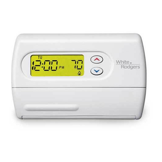
CHECK CHECK CHECK CHECK CHECK THERMOST THERMOST THERMOST THERMOST THERMOSTA A A A A T OPERA T OPERA T OPERA T OPERA T OPERATION TION TION TION TION Emergency System NOTE EMER bypasses the Heat Pump to use the heat source wired to terminal E on the thermostat. - Page 5 OPERA OPERA TION TION OPERA OPERATION OPERA TION TION Before you begin programming your thermostat, you should be familiar with its features and with the display and the location and operation of the thermostat buttons. Your thermostat con- sists of two parts: the thermostat cover and the base. To remove the cover, pull it straight out from the base.
-
Page 6: Installer/Configuration Menu
CONFIGURA CONFIGURA TION MENU TION MENU CONFIGURA CONFIGURA CONFIGURATION MENU TION MENU TION MENU Press the SYSTEM button until OFF is displayed, then press the simultaneously INSTALLER/CONFIGURATION MENU Press Displayed Press Step Button(s) (Factory Default) to select Comments System MS 2 SS1, HP2, HP1 Selects Single Stage, Multi-Stage, or Heat Pump (Single Stage or 2-stage) System Configuration... -
Page 7: Electrical Data
CONFIGURA CONFIGURA CONFIGURA CONFIGURA CONFIGURATION MENU TION MENU TION MENU TION MENU TION MENU 5) Fast or Slow Cycle Selection – The factory default setting 11)Select F° or C° Readout – Changes the display readout is fast cycle, which cycles 1st stage at approximately 1.2°F to Centigrade or Fahrenheit as required. -
Page 8: Programming Your Thermostat
OPERA OPERA TION TION OPERA OPERA OPERATION TION TION • LOW BATTERY INDICATOR LOW BATTERY INDICATOR LOW BATTERY INDICATOR LOW BATTERY INDICATOR LOW BATTERY INDICATOR — If the 2 “AA” alkaline batter- The system "mode" is selected by pressing the SYSTEM ies are low and should be replaced, the display will be blank button. - Page 9 OPERA OPERA TION TION OPERA OPERATION OPERA TION TION 5. Press TIME once again. The display will show the day of the weekday 1st period heating 1st period heating 1st period heating 1st period heating start time and temperature and 1st period heating the week.
-
Page 10: Enter Cooling Program
OPERA OPERA TION TION OPERA OPERA OPERATION TION TION Enter Cooling Program Enter Cooling Program Enter Cooling Program Enter Cooling Program Enter Cooling Program CHECK YOUR PROGRAMMING Follow these steps to check your thermostat programming CAUTION one final time before beginning thermostat operation. If the outside temperature is below 50°F, disconnect If the outside temperature is below 50°F, disconnect If the outside temperature is below 50°F, disconnect... - Page 11 TROUBLESHOO OUBLESHOO OUBLESHOO OUBLESHOOTING OUBLESHOO TING TING TING TING Possible Cause Corrective Action Symptom 1. SYSTEM button not pressed to COOL. Press SYSTEM button to COOL and lower setpoint No Cool below room temperature. 2. Loose connection to thermostat or Verify thermostat and system wires are securely system.
- Page 12 F F F F F A A A A A Q Q Q Q Q Symptom Corrective Action My thermostat is reading in Celsius. Your thermostat display can be set to display temperature in Fahrenheit or How do I change it to Fahrenheit? Celsius.
Need help?
Do you have a question about the 1F85-275 and is the answer not in the manual?
Questions and answers