White Rodgers 1F85RF-275 Installation And Operating Instructions Manual
Thermostat and wireless remote sensor kit
Hide thumbs
Also See for 1F85RF-275:
- Quick installation manual (20 pages) ,
- Quick installation manual (20 pages)
Advertisement
Quick Links
FAILURE TO READ AND FOLLOW ALL INSTRUCTIONS
FAILURE TO READ AND FOLLOW ALL INSTRUCTIONS
FAILURE TO READ AND FOLLOW ALL INSTRUCTIONS
FAILURE TO READ AND FOLLOW ALL INSTRUCTIONS
FAILURE TO READ AND FOLLOW ALL INSTRUCTIONS
CAREFULLY BEFORE INSTALLING OR OPERATING THIS
CAREFULLY BEFORE INSTALLING OR OPERATING THIS
CAREFULLY BEFORE INSTALLING OR OPERATING THIS
CAREFULLY BEFORE INSTALLING OR OPERATING THIS
CAREFULLY BEFORE INSTALLING OR OPERATING THIS
CONTROL COULD CAUSE PERSONAL INJURY AND/OR
CONTROL COULD CAUSE PERSONAL INJURY AND/OR
CONTROL COULD CAUSE PERSONAL INJURY AND/OR
CONTROL COULD CAUSE PERSONAL INJURY AND/OR
CONTROL COULD CAUSE PERSONAL INJURY AND/OR
PROPERTY DAMAGE.
PROPERTY DAMAGE.
PROPERTY DAMAGE.
PROPERTY DAMAGE.
PROPERTY DAMAGE.
APPLICATIONS
APPLICATIONS
APPLICATIONS
APPLICATIONS
APPLICATIONS
THERMOSTAT APPLICATION GUIDE
THERMOSTAT APPLICATION GUIDE
THERMOSTAT APPLICATION GUIDE
THERMOSTAT APPLICATION GUIDE
THERMOSTAT APPLICATION GUIDE
Description
Description
Description
Description
Description
Heat Pump (No Auxiliary or Emergency Heat)
Heat Pump (with Auxiliary or Emergency Heat)
Standard Heat & Cooling Systems
Multi-Stage Systems requiring more than
One Call for Heat or Cool
Standard Heat Only Systems
Millivolt Heat Only Systems – Floor or Wall Furnaces
Standard Central Air Conditioning
Gas or Oil Heat
Electric Furnace
Hydronic (Hot Water) Zone Heat – 2 Wires
Hydronic (Hot Water) Zone Heat – 3 Wires
* Common Connection Required
SPECIFICATIONS
SPECIFICATIONS
SPECIFICATIONS
SPECIFICATIONS
SPECIFICATIONS
Thermostat
Thermostat
Thermostat
Thermostat:
Thermostat
Electrical Ratings .......................... 20 to 30 VAC 50/60 Hz
Setpoint Range .............................. 45 to 90°F (7 to 32°C)
Rated Differential (Single Stage) ... Heat 0.6° or 1.5°F, Cool 1.2°F
Rated Differential (Multi-Stage) ..... Heat 0.6° or 1.5°F, Cool 1.2°F
Rated Differential (Heat Pump) ..... Heat & Cool 0.75° or 1.2°F
Operating Ambient ........................ 32 to +105°F (0 to +41°C)
Operating Humidity ....................... 90% non-condensing max.
Shipping Temp. Range .................. -4 to +150°F (-20 to +65°C)
Thermostat Dimensions ............... 3-3/4"H x 6"W x 1-1/4"D
CAUTION
!
To prevent electrical shock and/or equipment dam-
To prevent electrical shock and/or equipment dam-
To prevent electrical shock and/or equipment dam-
To prevent electrical shock and/or equipment dam-
To prevent electrical shock and/or equipment dam-
age, disconnect electric power to system at main fuse
age, disconnect electric power to system at main fuse
age, disconnect electric power to system at main fuse
age, disconnect electric power to system at main fuse
age, disconnect electric power to system at main fuse
or circuit breaker box until installation is complete.
or circuit breaker box until installation is complete.
or circuit breaker box until installation is complete.
or circuit breaker box until installation is complete.
or circuit breaker box until installation is complete.
Index
Installation
Wiring Connections
Thermostat/Sensor Quick Reference
Installer Configuration Menus
Operating Your Thermostat and Sensor
Programming
Troubleshooting
Save these instructions
Save these instructions
Save these instructions
Save these instructions
Save these instructions
for future use!
for future use!
for future use!
for future use!
for future use!
Yes
Yes
Yes
Yes
Yes
No
Yes
Yes
Yes
* Yes
No
0.2 to 0.6 Amps per Load
(Y1, E/W1, G)
1.5 Amps (Y2, W2, O, B
Load per terminal)
1.5 Amps Max
(All terminals combined)
Page
2
3
4
6
9
13
14
www.white-rodgers.com
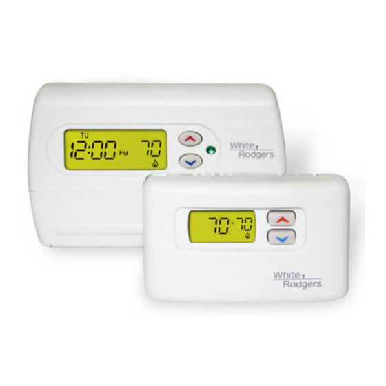
1F85RF-275 Thermostat and
Wireless Remote Sensor Kit
Automatic Heat/Cool Changeover Thermostat for Single Stage/
Multi-Stage/Heat Pump Systems with Wireless Remote Sensor
Installation and Operating Instructions for Model:
Installation and Operating Instructions for Model:
Installation and Operating Instructions for Model:
Installation and Operating Instructions for Model:
Installation and Operating Instructions for Model:
Model
1F85RF-270
Non-Programmable
F145RF-1328
1F85RF-270
Remote Sensor:
Remote Sensor:
Remote Sensor:
Remote Sensor:
Remote Sensor:
This device complies with Part 15 of the FCC Rules, Operation
This device complies with Part 15 of the FCC Rules, Operation
This device complies with Part 15 of the FCC Rules, Operation
This device complies with Part 15 of the FCC Rules, Operation
This device complies with Part 15 of the FCC Rules, Operation
is subject to the following two conditions: (1) this device may
is subject to the following two conditions: (1) this device may
is subject to the following two conditions: (1) this device may
is subject to the following two conditions: (1) this device may
is subject to the following two conditions: (1) this device may
not cause harmful interference, and (2) this device must accept
not cause harmful interference, and (2) this device must accept
not cause harmful interference, and (2) this device must accept
not cause harmful interference, and (2) this device must accept
not cause harmful interference, and (2) this device must accept
any interference received, including interference that may cause
any interference received, including interference that may cause
any interference received, including interference that may cause
any interference received, including interference that may cause
any interference received, including interference that may cause
undesired operation.
undesired operation.
undesired operation.
undesired operation.
undesired operation.
Maximum Wireless Remote Sensors ..... 1 indoor, 1 outdoor
Operating Range .................................... 45 to 90°F (7 to 32°C)
Operating Humidity Range ..................... 0 to 90% RH
Dimensions ............................................. 2-5/8"H x 4-1/4"W x 7/8"D
* Max. Distance from Thermostat .......... 200 feet
* Distance shown is for a typical application. Distances may vary in
some applications because obstacles that block the signal path
may affect the strength of the signal.
ATTENTION: MERCURY NOTICE
ATTENTION: MERCURY NOTICE
ATTENTION: MERCURY NOTICE
ATTENTION: MERCURY NOTICE
ATTENTION: MERCURY NOTICE
This product does not contain mercury. However, this prod-
uct may replace a product which contains mercury.
Mercury and products containing mercury must not be dis-
carded in household trash. Do not touch any spilled mercury.
Wearing non-absorbent gloves, clean up any spilled mercury
and place in a sealed container. For proper disposal of a
product containing mercury or a sealed container of spilled
mercury, place it in a suitable shipping container and send it
to:
White-Rodgers
White-Rodgers
White-Rodgers
White-Rodgers
White-Rodgers
2895 Harrison Street
2895 Harrison Street
2895 Harrison Street
2895 Harrison Street
2895 Harrison Street
Batesville, AR 72501
Batesville, AR 72501
Batesville, AR 72501
Batesville, AR 72501
Batesville, AR 72501
Programming Choices
5/1/1 Day
Wireless Remote Sensor
Wireless Remote Sensor
(non-condensing)
PART NO. 37-6841B
PART NO. 37-6841B
PART NO. 37-6841B
PART NO. 37-6841B
PART NO. 37-6841B
Replaces 37-6841A
0745
Advertisement

Related Manuals for White Rodgers 1F85RF-275


Summary of Contents for White Rodgers 1F85RF-275
- Page 1 1F85RF-275 Thermostat and Save these instructions Save these instructions Save these instructions Save these instructions Save these instructions Wireless Remote Sensor Kit for future use! for future use! for future use! for future use! for future use! Automatic Heat/Cool Changeover Thermostat for Single Stage/...
- Page 2 INSTALLATION INSTALLATION INSTALLATION INSTALLATION INSTALLATION 8. Remove the battery tags in both the thermostat and WARNING sensor and replace the covers by lining them up with the Thermostat installation and all components of the Thermostat installation and all components of the Thermostat installation and all components of the Thermostat installation and all components of the Thermostat installation and all components of the...
- Page 3 WIRING CONNECTIONS WIRING CONNECTIONS WIRING CONNECTIONS WIRING CONNECTIONS WIRING CONNECTIONS Typical wiring diagrams are provided below for the following systems: Single Stage Heat/Cool systems Multi-Stage Heat/Cool systems (No Heat Pump) Heat Pump system, one compressor or one speed compressor with Aux. Heat Heat Pump systems, two compressors or two speed compressor with Aux.
- Page 4 THERMOSTAT/REMOTE SENSOR QUICK REFERENCE THERMOSTAT/REMOTE SENSOR QUICK REFERENCE THERMOSTAT/REMOTE SENSOR QUICK REFERENCE THERMOSTAT/REMOTE SENSOR QUICK REFERENCE THERMOSTAT/REMOTE SENSOR QUICK REFERENCE Before operating the thermostat, familiarize yourself with the display and button functions. Both thermostat and remote sensor consist of two parts: the cover and the base. To remove a cover, pull it straight out from the base.
- Page 5 THERMOSTAT/SENSOR QUICK REFERENCE THERMOSTAT/SENSOR QUICK REFERENCE THERMOSTAT/SENSOR QUICK REFERENCE THERMOSTAT/SENSOR QUICK REFERENCE THERMOSTAT/SENSOR QUICK REFERENCE The Sensor Buttons and Display The Sensor Buttons and Display The Sensor Buttons and Display The Sensor Buttons and Display The Sensor Buttons and Display Figure 8 –...
- Page 6 THERMOST THERMOST THERMOST THERMOST THERMOSTA A A A A T CONFIGURA T CONFIGURA T CONFIGURA T CONFIGURA T CONFIGURATION MENU TION MENU TION MENU TION MENU TION MENU INSTALLER/CONFIGURATION MENU INSTALLER/CONFIGURATION MENU INSTALLER/CONFIGURATION MENU INSTALLER/CONFIGURATION MENU INSTALLER/CONFIGURATION MENU Press the System button until OFF OFF is displayed, then press the simultaneously Press...
- Page 7 THERMOST THERMOST THERMOST THERMOST THERMOSTA A A A A T CONFIGURA T CONFIGURA T CONFIGURA T CONFIGURA T CONFIGURATION MENU TION MENU TION MENU TION MENU TION MENU setting on the remote. This is only used in areas where 4° higher or lower. Your thermostat was accurately there are other wireless devices or electronic equipment calibrated at the factory but you have the option to that interfere with the default frequency of the thermostat/...
- Page 8 REMO REMO REMO REMO REMOTE SENSOR CONFIGURA TE SENSOR CONFIGURA TE SENSOR CONFIGURA TE SENSOR CONFIGURA TE SENSOR CONFIGURATION MENU TION MENU TION MENU TION MENU TION MENU The configuration menus allow you to set certain remote sensor operating characteristics to your system or personal require- ments.
- Page 9 REMO REMO REMO REMO REMOTE SENSOR CONFIGURA TE SENSOR CONFIGURA TE SENSOR CONFIGURA TE SENSOR CONFIGURA TE SENSOR CONFIGURATION MENU TION MENU TION MENU TION MENU TION MENU Installer Configuration Menu Installer Configuration Menu Installer Configuration Menu Installer Configuration Menu Installer Configuration Menu Your thermostat is configured at the factory to recognize the remote sensor it is shipped with as indoor sensor A.
- Page 10 OPERATING YOUR THERMOSTAT AND REMOTE SENSOR OPERATING YOUR THERMOSTAT AND REMOTE SENSOR OPERATING YOUR THERMOSTAT AND REMOTE SENSOR OPERATING YOUR THERMOSTAT AND REMOTE SENSOR OPERATING YOUR THERMOSTAT AND REMOTE SENSOR Emergency System Emergency System Emergency System Automatic System Changeover Automatic System Changeover Automatic System Changeover Emergency System Emergency System...
- Page 11 OPERATING YOUR THERMOSTAT AND REMOTE SENSOR OPERATING YOUR THERMOSTAT AND REMOTE SENSOR OPERATING YOUR THERMOSTAT AND REMOTE SENSOR OPERATING YOUR THERMOSTAT AND REMOTE SENSOR OPERATING YOUR THERMOSTAT AND REMOTE SENSOR Learn Mode Option Learn Mode Option Learn Mode Option Learn Mode Option Learn Mode Option 70°F then: If weight selected is HI , then the averaged temperature is...
- Page 12 OPERATING YOUR THERMOSTAT AND REMOTE SENSOR OPERATING YOUR THERMOSTAT AND REMOTE SENSOR OPERATING YOUR THERMOSTAT AND REMOTE SENSOR OPERATING YOUR THERMOSTAT AND REMOTE SENSOR OPERATING YOUR THERMOSTAT AND REMOTE SENSOR Remote Sensor Operation Remote Sensor Operation Remote Sensor Operation Remote Sensor Operation Remote Sensor Operation PROGRAMMING YOUR THERMOSTAT PROGRAMMING YOUR THERMOSTAT...
- Page 13 PROGRAMMING PROGRAMMING PROGRAMMING PROGRAMMING PROGRAMMING Setting the Clock and Day Setting the Clock and Day Setting the Clock and Day Setting the Clock and Day Setting the Clock and Day 6. Press PRGM once. The currently programmed start time and setpoint temperature for the 2nd heating 2nd heating 2nd heating 2nd heating...
- Page 14 TROUBLESHOOTING TROUBLESHOOTING TROUBLESHOOTING TROUBLESHOOTING TROUBLESHOOTING Reset Operation Reset Operation Reset Operation Reset Operation Reset Operation If a voltage spike or static discharge blanks out the display or causes erratic thermostat operation, you can reset the thermo- stat by removing the wires from terminals R and C and removing batteries for 2 minutes. After resetting the thermostat, replace the wires and batteries.
- Page 15 TROUBLESHOOTING TROUBLESHOOTING TROUBLESHOOTING TROUBLESHOOTING TROUBLESHOOTING Possible Cause Possible Cause Corrective Action Corrective Action Symptom Symptom Possible Cause Possible Cause Possible Cause Corrective Action Corrective Action Corrective Action Symptom Symptom Symptom In power stealing mode (RC/PS Switch 1. Add a common connection from the system Furnace Inducer Fan, Furnace Inducer Fan, Furnace Inducer Fan,...
- Page 16 TROUBLESHOOTING TROUBLESHOOTING TROUBLESHOOTING TROUBLESHOOTING TROUBLESHOOTING Possible Cause Possible Cause Possible Cause Possible Cause Possible Cause Corrective Action Corrective Action Corrective Action Corrective Action Corrective Action Symptom Symptom Symptom Symptom Symptom 1. The location of the thermostat and/or Digital thermostats normally provide precise Furnace Furnace Furnace...
Need help?
Do you have a question about the 1F85RF-275 and is the answer not in the manual?
Questions and answers
Showing fault on display and no ac
The fault display on a White Rodgers 1F85RF-275 thermostat indicates system issues using LED flash codes. Each code corresponds to a specific fault:
1. Code 1 (24 VAC lost) – Indicates loss of power. Possible cause: Power Mode Switch S7 set to RC and no common wire connected to C terminal.
Resolution: Check wiring and ensure common wire is connected properly.
2. Code 2 (Invalid packet) – Receiver detected a bad signal. Causes include poor antenna positioning, bad sensor location, noise, or interference.
Resolution: Reposition antenna or sensor, reduce interference. To override, press and hold RUN for 4 seconds (resets on power-up).
3. Code 3 (Unidentified packet) – Receiver not programmed to sensor or signal conflict with another device.
Resolution: Program (learn) receiver to the correct sensor.
4. Code 4 (No communication) – Thermostat failed to communicate with receiver.
Resolution: Check receiver installation or replace inoperative module.
5. Code 5 (Sensor not responding) – Indoor remote sensor failed.
Resolution: Check or replace the indoor sensor.
Always correct the highest priority error first; only one code is shown at a time.
This answer is automatically generated