Grizzly G0636X Owner's Manual
17" ultimate bandsaw
Hide thumbs
Also See for G0636X:
- Owner's manual (64 pages) ,
- Parts breakdown (6 pages) ,
- Owner's manual (84 pages)
Table of Contents
Advertisement
Quick Links
MODEL G0636X
17" ULTIMATE BANDSAW
OWNER'S MANUAL
(For models manufactured since 09/18)
COPYRIGHT © MAY, 2007 BY GRIZZLY INDUSTRIAL, INC., REVISED FEBRUARY, 2020 (MN)
WARNING: NO PORTION OF THIS MANUAL MAY BE REPRODUCED IN ANY SHAPE
OR FORM WITHOUT THE WRITTEN APPROVAL OF GRIZZLY INDUSTRIAL, INC.
#BL9291 PRINTED IN TAIWAN
V6.02.20
Advertisement
Table of Contents

Related Manuals for Grizzly G0636X


Summary of Contents for Grizzly G0636X
- Page 1 OWNER'S MANUAL (For models manufactured since 09/18) COPYRIGHT © MAY, 2007 BY GRIZZLY INDUSTRIAL, INC., REVISED FEBRUARY, 2020 (MN) WARNING: NO PORTION OF THIS MANUAL MAY BE REPRODUCED IN ANY SHAPE OR FORM WITHOUT THE WRITTEN APPROVAL OF GRIZZLY INDUSTRIAL, INC.
- Page 2 This manual provides critical safety instructions on the proper setup, operation, maintenance, and service of this machine/tool. Save this document, refer to it often, and use it to instruct other operators. Failure to read, understand and follow the instructions in this manual may result in fire or serious personal injury—including amputation, electrocution, or death.
-
Page 3: Table Of Contents
Table of Contents INTRODUCTION ..........2 SECTION 5: ACCESSORIES ......41 Contact Info............ 2 SECTION 6: MAINTENANCE ......43 Manual Accuracy ........... 2 Schedule ............43 Machine Data Sheet ........3 Cleaning & Protecting ........43 Identification ........... 5 Brushes ............43 Controls &... -
Page 4: Introduction
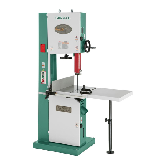
Use this machine with respect and caution to lessen the pos- sibility of operator injury. If normal safety precautions are overlooked or ignored, seri- Manufacture Date ous personal injury may occur. Serial Number Model G0636X (Mfd. Since 09/18) -
Page 5: Machine Data Sheet
MACHINE DATA SHEET Customer Service #: (570) 546-9663 · To Order Call: (800) 523-4777 · Fax #: (800) 438-5901 MODEL G0636X 17" 5 HP ULTIMATE BANDSAW Product Dimensions: Weight................................620 lbs. Width (side-to-side) x Depth (front-to-back) x Height............35-1/4 x 33-3/4 x 78-1/2 in. - Page 6 Includes 1" Blade Included Miter Gauge Cast-Iron Table Trunnion Heavy-Duty Quick-Lock Cast-Iron Fence with Removable Resaw Fence Computer Balanced Cast-Iron Wheels with Grizzly Bear Head Cut-Outs Rack and Pinion Upper Guide Adjustment Foot Brake Stop Optional Extension Table with Support The information contained herein is deemed accurate as of 3/11/2020 and represents our most recent product specifications.
-
Page 7: Identification
Do not remove jammed cutoff pieces until blade has stopped. Maintain proper adjustment of blade tension, blade guides, and thrust bearings. d) Adjust upper guide to just clear workpiece. Hold workpiece firmly against table. Model G0636X (Mfd. Since 09/18) -
Page 8: Controls & Components
(refer to Page 34). Figure 2. Rear controls. Quick Release Blade Tension Lever: Releases blade tension for quick blade changes. K. Blade Tracking Knob and Lock Lever: Moves and locks blade tracking. Model G0636X (Mfd. Since 09/18) -
Page 9: Section 1: Safety
Never operate under the influence of drugs or injury or blindness from flying particles. Everyday alcohol, when tired, or when distracted. eyeglasses are NOT approved safety glasses. Model G0636X (Mfd. Since 09/18) - Page 10 EXPERIENCING DIFFICULTIES. If at any time debris. Make sure they are properly installed, you experience difficulties performing the intend- undamaged, and working correctly BEFORE ed operation, stop using the machine! Contact our operating machine. Technical Support at (570) 546-9663. Model G0636X (Mfd. Since 09/18)
-
Page 11: Additional Safety For Bandsaws
DO NOT try to stop or slow blade with your This machine is NOT designed to cut metal, hand or the workpiece. glass, stone, tile, etc. Model G0636X (Mfd. Since 09/18) -
Page 12: Section 2: Power Supply
To reduce the risk of these hazards, avoid over- loading the machine during operation and make sure it is connected to a power supply circuit that meets the specified circuit requirements. -10- Model G0636X (Mfd. Since 09/18) - Page 13 -11- Model G0636X (Mfd. Since 09/18)
-
Page 14: Section 3: Setup
IMPORTANT: Save all packaging materials until you are completely satisfied with the machine and have resolved any issues between Grizzly or the shipping agent. You MUST have the original pack- aging to file a freight claim. It is also extremely helpful if you need to return your machine later. -
Page 15: Hardware Recognition Chart
Hardware Recognition Chart -13- Model G0636X (Mfd. Since 09/18) -
Page 16: Inventory
B. Cast Iron Fence Assembly ......1 ing or they are pre-installed at the factory. C. Resaw Fence ..........1 D. Guide Post Handwheel....... 1 E. Miter Gauge ..........1 Figure 4. Loose inventory components. -14- Model G0636X (Mfd. Since 09/18) -
Page 17: Cleanup
Figure 5. T23692 Orange Power Degreaser Repeat Steps 2–3 as necessary until clean, then coat all unpainted surfaces with a quality metal protectant to prevent rust. -15- Model G0636X (Mfd. Since 09/18) -
Page 18: Site Considerations
Only install in an Shadows, glare, or strobe effects that may distract access restricted location. or impede the operator must be eliminated. " " Figure 6. Minimum working clearances. -16- Model G0636X (Mfd. Since 09/18) -
Page 19: Moving & Placing Base Unit
Note: If you are concerned about your forklift Remove pallet and slowly set bandsaw into forks hitting the tension handwheel, remove the position. handwheel, then re-install it after lifting. Figure 7. Lifting the bandsaw. -17- Model G0636X (Mfd. Since 09/18) -
Page 20: Mounting To Shop Floor
Figure 10. Bandsaw mounted on D2058A mobile wheel retracting capabilities that keep the mobile base. base from rolling when the bandsaw is in use. We recommend using the Grizzly Model D2058A mobile base. Guide Post Handwheel Bolting to Concrete Floors... -
Page 21: Blade Tracking
Wheel tension scale for appropriate blade thickness (see Figure 12). Figure 13. Center tracking profiles. Blade Tension CENTER TRACKING Scale Blade Tension Handwheel Figure 12. Blade tensioning controls. -19- Model G0636X (Mfd. Since 09/18) -
Page 22: Positive Stop
Stop NOTICE Jam Nut Bolt Changes in the blade tension may change the blade tracking. Figure 15. Positive stop bolt and jam nut (as viewed from front). -20- Model G0636X (Mfd. Since 09/18) -
Page 23: Dust Collection
Figure 16. Adjust table square with blade using table tilt handwheel, then secure with table tilt lock lever. DO NOT operate the Model G0636X without an adequate dust collection system. This saw creates substantial amounts of wood dust while operating. Failure to use a dust collection system can result in short and long-term respiratory illness. -
Page 24: Installing Fence
(see Figure 18), then slide resaw fence over moving plate. Resaw Fence Resaw Lock Handle Fence Handle Rail Figure 19. Fence installed on table. Moving Plate Figure 18. Example of attaching resaw fence to standard fence. -22- Model G0636X (Mfd. Since 09/18) -
Page 25: Test Run
Always disconnect Figure 21. Resetting the switch. machine from power when investigating or correcting potential problems. Turn switch disabling key to "0", as shown in Figure 20. -23- Model G0636X (Mfd. Since 09/18) -
Page 26: Tensioning Blade
(See Figure 12, Page 19). Turn bandsaw ON. Slowly release tension one quarter of a turn at a time. When bandsaw blade starts to flut- ter, stop decreasing tension. -24- Model G0636X (Mfd. Since 09/18) - Page 27 Note: 0.004" is approximately the thickness ings are " behind blade gullets, as illus- of a dollar bill. trated in Figure 24. Tighten both bearing rotation adjustment bolts to lock blade guide bearings in position. -25- Model G0636X (Mfd. Since 09/18)
-
Page 28: Adjusting Support Bearings
DISCONNECT MACHINE FROM POWER! Guide Block Assembly Cap Screws Familiarize yourself with upper support bear- ing controls shown in Figure 22 & 23. Lateral Adjustment Rod Cap Screw Figure 26. Lower blade guide controls (rear view). -26- Model G0636X (Mfd. Since 09/18) - Page 29 Support Bearing Support Adjustment Shaft Bolt Bearing Side View Blade Figure 28. Blade aligned 0.016" away from the bearing edge. Support Bearing Figure 30. Lower support bearing controls. Open upper and lower wheel covers. -27- Model G0636X (Mfd. Since 09/18)
-
Page 30: Aligning Table
DISCONNECT MACHINE FROM POWER! Loosen four trunnion cap screws that secure table to trunnions (see Figure 31). Figure 32. Example of measuring for miter slot to be parallel with blade. -28- Model G0636X (Mfd. Since 09/18) -
Page 31: Aligning Fence
Adjusting the fence parallel to the miter slot does not guarantee straight cuts. The miter slot may need to be adjusted parallel to the side of the blade. Refer to the "Aligning Table" instructions on Page 28. -29- Model G0636X (Mfd. Since 09/18) -
Page 32: Calibrating Pointer
Place fence flush against bandsaw blade Figure 36. Location of fence pointer adjustment (see Figure 35). screw. Tighten pointer adjustment nut. Figure 35. Example of fence flush with blade. -30- Model G0636X (Mfd. Since 09/18) -
Page 33: Section 4: Operations
Regardless of the content in this section, Grizzly Industrial will not be held liable for accidents caused by lack of training. -31- Model G0636X (Mfd. Since 09/18) -
Page 34: Workpiece Inspection
On the contrary, a workpiece supported on the bowed side will rock during a cut and could cause kickback or severe injury. -32- Model G0636X (Mfd. Since 09/18) -
Page 35: Foot Brake
Foot Brake Table Tilt The Model G0636X is equipped with a foot brake (see Figure 37). Use the brake only in emergency situations to stop power from going to the motor Personal injury or death and bring the blade to a halt. -
Page 36: Guide Post
Turn guide post handwheel to raise or lower guide post until upper blade guide assembly Tighten the lock lever so the tracking knob is within 1" from top of workpiece. cannot move. Lock guide post in place with lock knob. -34- Model G0636X (Mfd. Since 09/18) -
Page 37: Blade Lead
To skew fence: Cut a piece of scrap wood approximately ⁄ " thick x 3" wide x 17" long. On a wide face of the board, draw a straight line parallel to long edge. -35- Model G0636X (Mfd. Since 09/18) -
Page 38: Ripping
In the event that something unexpected happens, your hands or fingers may slip into the blade. ALWAYS use a push stick when ripping narrow pieces. Failure to fol- low these warnings may result in serious personal injury! -36- Model G0636X (Mfd. Since 09/18) -
Page 39: Resawing
Using push paddles and a push stick, keep ⁄ '' ........3 ⁄ pressure against fence and table, and slowly ⁄ '' ........5 ⁄ feed workpiece into moving blade until blade is completely through workpiece (see Figure 44). -37- Model G0636X (Mfd. Since 09/18) -
Page 40: Stacked Cuts
To complete a stacked cut: and the distance between wheels. The Model G0636X is designed for blades that are 160" long. Align pieces from top to bottom to ensure that Refer to Page 41 for blade replacements. - Page 41 However, these blades also leave a rougher operator when mounting or adjusting the blade or cut than raker blades. support guides. -39- Model G0636X (Mfd. Since 09/18)
-
Page 42: Changing Blade
(see Page 24). wear leather gloves when handling saw blades. Replace table insert and table pin. To remove a blade: Close wheel covers. DISCONNECT MACHINE FROM POWER! Release blade tension. -40- Model G0636X (Mfd. Since 09/18) -
Page 43: Section 5: Accessories
3 HOOK NOTICE H4824 1" 6 HOOK H4825 1" 2 HOOK Refer to the newest copy of the Grizzly Catalog for other accessories available for 162" Timber Wolf Replacement Blades for the ® this machine. Model G0636X. Replacement Blades MODEL... - Page 44 55-gallon collection capacity. Figure 51. Recommended products for protect- ing unpainted cast iron/steel on machinery. Figure 53. Model G0862 3 HP Portable Cyclone Dust Collector. www.grizzly.com 1-800-523-4777 order online at or call -42- Model G0636X (Mfd. Since 09/18)
-
Page 45: Section 6: Maintenance
Always disconnect power to the machine before performing maintenance. Failure to do this may Cleaning the Model G0636X is relatively easy. result in serious person- Vacuum excess wood chips and sawdust, and al injury. wipe off the remaining dust with a dry cloth. If any... - Page 46 Unscrew blade tracking knob 5 turns. Wipe off any existing grease and sawdust buildup on threads. Apply a few dabs of a light all-purpose grease to threads. Re-adjust tracking (see Blade Tracking on Page 19). -44- Model G0636X (Mfd. Since 09/18)
- Page 47 Apply a thin coat of light all-purpose grease to ute grease, then wipe off any excess grease from trunnions. rack. Move table up and down several times to distribute grease, then wipe off any excess grease. -45- Model G0636X (Mfd. Since 09/18)
-
Page 48: Section 7: Service
9. Motor bearings are at fault. 9. Test by rotating shaft; rotational grinding/loose shaft requires bearing replacement. 10. Motor has overheated. 10. Let motor cool, clean it off, and reduce workload. 11. Motor is at fault. 11. Repair/replace. -46- Model G0636X (Mfd. Since 09/18) - Page 49 —Check dust lines for leaks or clogs. —Move dust collector closer to saw. —Install a stronger dust collector. Blade wanders or 1. Blade lead. 1. Refer to Blade Lead on Page 35. won't follow line of cut. -47- Model G0636X (Mfd. Since 09/18)
-
Page 50: Checking And Tensioning V-Belts
If deflection is more ", repeat Step 4. than ⁄ When V-belt tension is correct, tighten motor adjustment bolts, and close wheel covers. Deflection Bandsaw Wheel Figure 58. V-belt deflection. -48- Model G0636X (Mfd. Since 09/18) -
Page 51: Replacing V-Belts
Engage tension lever and test blade tension. tighten wheel mount cap screw, and tension V-beltS (see Page 48). Repeat Steps 1–5 until tension lever adds right amount of tension to blade when it is Close lower wheel cover. engaged. -49- Model G0636X (Mfd. Since 09/18) -
Page 52: Adjusting Wheel And Blade Brushes
Tighten bolt/nuts to secure each brush in sion that it will be used during operation. place. -50- Model G0636X (Mfd. Since 09/18) - Page 53 ⁄ " washers on shaft behind wheel. 17" Side View Figure 63. Dimensions of coplanarity gauge. Coplanarity Gauge Positions Gauge Tracking Knob Wheels Adjustment Figure 64. Checking for coplanarity. -51- Model G0636X (Mfd. Since 09/18)
- Page 54 Pages 28 & 29). Parallel, Not Not Parallel Adjust Coplanar Coplanar Not Coplanar Tracking Knob Shim Upper Wheel Out Coplanarity Gauge Contacts Top And Bottom of Both Wheels Adjust Lower Figure 66. Coplanarity diagram. -52- Model G0636X (Mfd. Since 09/18)
-
Page 55: Adjusting Guide Post Travel
Loosen each of four screws shown in Figure ⁄ turn. Figure 67. Squaring table to blade. Adjust table square with blade using table tilt handwheel, then secure it with table tilt lock lever. Figure 69. Guide post adjustment screws. -53- Model G0636X (Mfd. Since 09/18) - Page 56 Go to Step 9. Re-install guide post guard with screws removed in Step 3. —If measurements taken in Steps 4 & 5 are not equal, go to Step 6. -54- Model G0636X (Mfd. Since 09/18)
-
Page 57: Section 8: Wiring
Technical Support at (570) 546-9663. The photos and diagrams included in this section are best viewed in color. You can view these pages in color at www.grizzly.com. -55- Model G0636X (Mfd. Since 09/18) -
Page 58: Electrical Components
Figure 75. Motor junction box wiring. Figure 73. Control panel wiring. Figure 74. Wheel cover limit switch (left) and foot brake switch (right). Figure 76. Magnetic switch wiring. READ ELECTRICAL SAFETY -56- Model G0636X (Mfd. Since 09/18) ON PAGE 55! -
Page 59: Wiring Diagram
U/2/T1 V/4/T2 W/6/T3 MAG SWITCH ASSY MPE-30 (Figure 76) FOOT BRAKE 230V MOTOR (Figure 75) (Figure 74) Limit Start Switch Capacitor KL7141 300MFD 250VAC Ground Capacitor 45MFD 450VAC READ ELECTRICAL SAFETY -57- Model G0636X (Mfd. Since 09/18) ON PAGE 55! -
Page 60: Section 9: Parts
94-6 94-3 94-1 94-5V2 105-2 105-4 114V2 105-1 105-3V2 103V2 94V2 105V2 74V2 74V2 13 37 65V3 64 117 118 70V2 BUY PARTS ONLINE AT GRIZZLY.COM! -58- Model G0636X (Mfd. Since 09/18) Scan QR code to visit our Parts Store. - Page 61 CONNECTING BLOCK P0636X100 TERMINAL BOX P0636X053 CONNECTING CORD 103V2 P0636X103V2 POWER CORD 12G 3W V2.11.10 P0636X054 SWITCH CORD P0636X104 STRAIN RELIEF M20 BUY PARTS ONLINE AT GRIZZLY.COM! -59- Model G0636X (Mfd. Since 09/18) Scan QR code to visit our Parts Store.
- Page 62 Please Note: We do our best to stock replacement parts whenever possible, but we cannot guarantee that all parts shown here are available for purchase. Call (800) 523-4777 or visit our online parts store at www.grizzly.com to check for availability.
-
Page 63: Fence/Guides/Trunnion
160-13 160-11 160-9 160-5 160-2 160-3 160-6 160-4 160-10 125 124V2 233V2 232 137V2 248 249 248 249 244 243 242 BUY PARTS ONLINE AT GRIZZLY.COM! -61- Model G0636X (Mfd. Since 09/18) Scan QR code to visit our Parts Store. - Page 64 TABLE INSERT P0636X219 CAP SCREW M6-1 X 10 P0636X162 SHAFT P0636X220 LOCK WASHER 6MM P0636X163 NYLON PIECE P0636X221 FLAT WASHER 6MM BUY PARTS ONLINE AT GRIZZLY.COM! -62- Model G0636X (Mfd. Since 09/18) Scan QR code to visit our Parts Store.
- Page 65 HEX BOLT M6-1 X 16 P0636X266 CAP SCREW M6-1 X 20 P0636X242 ECCENTRIC SHAFT P0636X277 CAP SCREW M6-1 X 12 P0636X243 EXT RETAINING RING 15MM BUY PARTS ONLINE AT GRIZZLY.COM! -63- Model G0636X (Mfd. Since 09/18) Scan QR code to visit our Parts Store.
-
Page 66: Labels & Cosmetics
Safety labels help reduce the risk of serious injury caused by machine hazards. If any label comes off or becomes unreadable, the owner of this machine MUST replace it in the original location before resuming operations. For replacements, contact (800) 523-4777 or www.grizzly.com. BUY PARTS ONLINE AT GRIZZLY.COM! -64- Model G0636X (Mfd. -
Page 67: Warranty And Returns
WARRANTY AND RETURNS Grizzly Industrial, Inc. warrants every product it sells for a period of 1 year to the original purchaser from the date of purchase. This warranty does not apply to defects due directly or indirectly to misuse, abuse, negligence, accidents, repairs or alterations or lack of maintenance.
Need help?
Do you have a question about the G0636X and is the answer not in the manual?
Questions and answers