Grizzly G0636X Owner's Manual
17" ultimate bandsaw
Hide thumbs
Also See for G0636X:
- Owner's manual (64 pages) ,
- Parts breakdown (6 pages) ,
- Owner's manual (68 pages)
Table of Contents
Advertisement
Quick Links
MODEL G0636X/G0636XB
17" ULTIMATE BANDSAW
OWNER'S MANUAL
(For models manufactured since 04/17)
COPYRIGHT © MAY, 2007 BY GRIZZLY INDUSTRIAL, INC., REVISED SEPTEMBER, 2017 (TR)
WARNING: NO PORTION OF THIS MANUAL MAY BE REPRODUCED IN ANY SHAPE
OR FORM WITHOUT THE WRITTEN APPROVAL OF GRIZZLY INDUSTRIAL, INC.
#BL9291 PRINTED IN TAIWAN
Advertisement
Table of Contents

Related Manuals for Grizzly G0636X


Summary of Contents for Grizzly G0636X
- Page 1 OWNER'S MANUAL (For models manufactured since 04/17) COPYRIGHT © MAY, 2007 BY GRIZZLY INDUSTRIAL, INC., REVISED SEPTEMBER, 2017 (TR) WARNING: NO PORTION OF THIS MANUAL MAY BE REPRODUCED IN ANY SHAPE OR FORM WITHOUT THE WRITTEN APPROVAL OF GRIZZLY INDUSTRIAL, INC.
- Page 2 This manual provides critical safety instructions on the proper setup, operation, maintenance, and service of this machine/tool. Save this document, refer to it often, and use it to instruct other operators. Failure to read, understand and follow the instructions in this manual may result in fire or serious personal injury—including amputation, electrocution, or death.
-
Page 3: Table Of Contents
SECTION 8: WIRING ........59 Mounting to Shop Floor ....... 17 Wiring Safety Instructions ......59 Guide Post Handwheel ........ 17 G0636X Electrical Components ....60 Blade Tracking ..........18 G0636X Wiring Diagram ......61 Positive Stop ..........19 G0636XB Electrical Components ....62 Dust Collection .......... -
Page 4: Introduction
Hold workpiece firmly against table. at www.grizzly.com. Any updates to your model of machine will be reflected in these documents as soon as they are complete. Model G0636X/G0636XB (Mfd. Since 04/17) -
Page 5: Machine Data Sheet
Cord & Plug Included Recommended Plug/Outlet L6-30 Type Motor Type TEFC Capacitor Start Induction Horsepower 5 HP Voltage 230V Phase Single-Phase Amperage Speed 1725 RPM Cycle 60 Hz Power Transfer Belt Drive Bearings Shielded & Permanently Lubricated Model G0636X/G0636XB (Mfd. Since 04/17) - Page 6 Motor Brake Wheel Diameter 17" Dust Ports 2 x 4" Mobile Base Model G7315Z Other Specifications Country of Origin Taiwan Warranty 1 Year Serial Number Location ID Label on Top Wheel Cover Assembly Time 1 Hour Model G0636X/G0636XB (Mfd. Since 04/17)
-
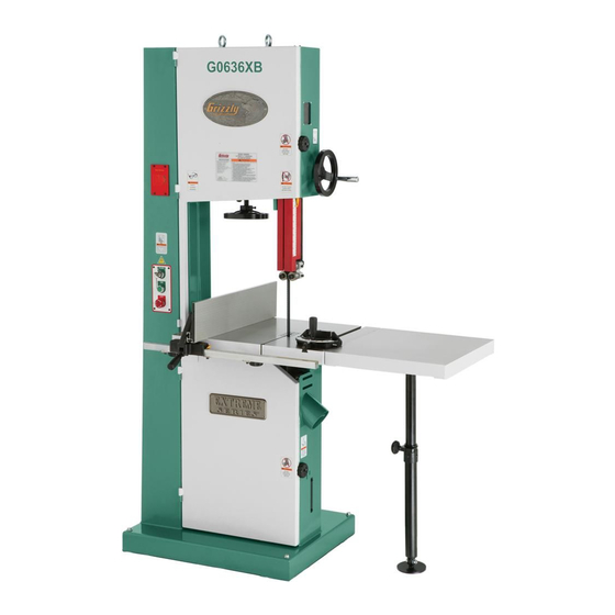
Page 7: Identification
Identification Figure 1. G0636X front view. Figure 2. G0636X rear view. A. Eye Bolt P. Quick Release Blade Tension Lever Q. Guide Post Lock Knob B. Hinged Wheel Covers R. Blade Tension Handwheel C. Blade Tracking Window D. Guide Post Handwheel S. -
Page 8: Section 1: Safety
Everyday ery. Never operate under the influence of drugs or eyeglasses are NOT approved safety glasses. alcohol, when tired, or when distracted. Model G0636X/G0636XB (Mfd. Since 04/17) - Page 9 EXPERIENCING DIFFICULTIES. If at any time debris. Make sure they are properly installed, you experience difficulties performing the intend- undamaged, and working correctly BEFORE ed operation, stop using the machine! Contact our operating machine. Technical Support at (570) 546-9663. Model G0636X/G0636XB (Mfd. Since 04/17)
-
Page 10: Additional Safety For Bandsaws
If normal safety pre- Failure to do so could result in serious per- sonal injury, damage to equipment, or poor cautions are overlooked or ignored, serious personal injury may occur. work results. Model G0636X/G0636XB (Mfd. Since 04/17) -
Page 11: Section 2: Power Supply
To reduce the risk of these hazards, avoid over- loading the machine during operation and make sure it is connected to a power supply circuit that meets the specified circuit requirements. Model G0636X/G0636XB (Mfd. Since 04/17) -
Page 12: Grounding Instructions
-10- Model G0636X/G0636XB (Mfd. Since 04/17) -
Page 13: Section 3: Setup
IMPORTANT: Save all packaging materials until you are completely satisfied with the machine and have resolved any issues between Grizzly or the shipping agent. You MUST have the original pack- aging to file a freight claim. It is also extremely helpful if you need to return your machine later. -
Page 14: Hardware Recognition Chart
Hardware Recognition Chart -12- Model G0636X/G0636XB (Mfd. Since 04/17) -
Page 15: Inventory
Crate Contents (Figure 4): A. Bandsaw (not shown) ......... 1 Figure 4. G0636X crate contents. B. Cast Iron Fence Assembly ......1 C. Resaw Fence ..........1 NOTICE D. -
Page 16: Cleanup
Repeat Steps 2–3 as necessary until clean, then coat all unpainted surfaces with a quality metal protectant to prevent rust. -14- Model G0636X/G0636XB (Mfd. Since 04/17) -
Page 17: Site Considerations
Only install in an Shadows, glare, or strobe effects that may distract access restricted location. or impede the operator must be eliminated. " " Figure 5. Minimum working clearances. -15- Model G0636X/G0636XB (Mfd. Since 04/17) -
Page 18: Moving & Placing Base Unit
Remove the pallet and slowly set the bandsaw Note: If you are concerned about your forklift into position. forks hitting the tension handwheel, remove the handwheel, then reinstall it after lifting. Figure 6. Lifting the bandsaw. -16- Model G0636X/G0636XB (Mfd. Since 04/17) -
Page 19: Mounting To Shop Floor
Figure 9. Bandsaw mounted on G7315 mobile wheel retracting capabilities that keep the mobile base. base from rolling when the bandsaw is in use. We recommend using the Grizzly Model G7315 mobile base. Guide Post Bolting to Concrete Floors Handwheel... -
Page 20: Blade Tracking
(Figure 11). Figure 12. Center tracking profiles. CENTER TRACKING Blade Tension Scale Blade Tension Handwheel Quick Tension Lever Figure 11. Blade tensioning controls. -18- Model G0636X/G0636XB (Mfd. Since 04/17) -
Page 21: Positive Stop
Stop Jam Nut NOTICE Bolt Changes in the blade tension may change the blade tracking. Figure 14. Positive stop bolt and jam nut (as viewed from front). -19- Model G0636X/G0636XB (Mfd. Since 04/17) -
Page 22: Dust Collection
DO NOT operate the Model G0636X without an adequate dust collection system. This saw creates substantial amounts of wood dust while operating. Failure to use a dust collection system can result in short and long-term respiratory illness. -
Page 23: Installing Fence
8mm washer and moving plate) onto the fence, then slide the resaw fence over the moving plate as shown in Figure 18. Note: Leave the moving plate and lock handle loose enough to slide on the resaw fence. -21- Model G0636X/G0636XB (Mfd. Since 04/17) -
Page 24: Power Connection
Turn the machine power switch OFF. Insert the power cord plug into a matching power supply receptacle. The machine is now connected to the power source. Figure 20. Disconnecting power. Figure 19. Connecting power. -22- Model G0636X/G0636XB (Mfd. Since 04/17) -
Page 25: Test Run
The motor powers up and runs correctly, 2) the Off Button safety disabling mechanism on the switch works correctly, and 3) the stop button safety feature Figure 21. G0636X switch disabling key and works correctly. ON/OFF switch. If, during the test run, you cannot easily locate Press the OFF button to stop the machine. -
Page 26: Tensioning Blade
(See Figure 11, Page 18). Turn the bandsaw ON. Slowly release the tension one quarter of a turn at a time. When you see the bandsaw blade start to flutter, stop decreasing the ten- sion. -24- Model G0636X/G0636XB (Mfd. Since 04/17) - Page 27 Note: 0.004" is approximately the thickness blade gullets, as illustrated in Figure 25. of a dollar bill. Tighten both of the the bearing rotation adjustment bolts to lock the blade guide bear- ings in position. -25- Model G0636X/G0636XB (Mfd. Since 04/17)
-
Page 28: Adjusting Support Bearings
DISCONNECT BANDSAW FROM POWER! Guide Block Assembly Cap Screws Familiarize yourself with the upper support bearing controls shown in Figure 23 & 24. Lateral Adjustment Rod Cap Screw Figure 27. Lower blade guide controls (rear view). -26- Model G0636X/G0636XB (Mfd. Since 04/17) - Page 29 Support Bearing Adjustment Shaft Bolt Support Bearing Side View Blade Support Bearing Figure 29. Blade aligned 0.016" away from the bearing edge. Figure 31. Lower support bearing controls. Open the upper and lower wheel covers. -27- Model G0636X/G0636XB (Mfd. Since 04/17)
-
Page 30: Aligning Table
DISCONNECT BANDSAW FROM POWER! Loosen the four trunnion cap screws that secure the table to the trunnions (Figure 32). Figure 33. Example of measuring for miter slot to be parallel with blade. -28- Model G0636X/G0636XB (Mfd. Since 04/17) -
Page 31: Aligning Fence
Adjusting the fence parallel to the miter slot does not guarantee straight cuts. The miter slot may need to be adjusted parallel to the side of the blade. Refer to the "Aligning Table" instructions on Page 28. -29- Model G0636X/G0636XB (Mfd. Since 04/17) -
Page 32: Pointer Calibration
To calibrate the pointer: If the fence is mounted on the right-hand side Figure 37. Model G0636X fence pointer of the blade, remove it and re-install it on the adjustment screw. left-hand side of the blade. -
Page 33: Section 4: Operations
Off Button Regardless of the content in this section, Grizzly Industrial will not be held liable for accidents caused by lack of training. Figure 39. Control panel features. -31-... -
Page 34: Front Controls
Moves and locks blade tracking. controlled cutting at various angles. Table Tilt Lock Lever: Locks or unlocks the E. Foot Brake (G0636X): Cuts power to motor table at the current angle. and allows bandsaw blade to be quickly Table Tilt Handwheel: Tilts the table up to brought to a stop. -
Page 35: Operation Overview
Note: The operator is very careful to keep fingers away from the blade and uses a push stick to feed narrow workpieces. Stops the bandsaw and removes the workpiece when the blade is completely stopped. -33- Model G0636X/G0636XB (Mfd. Since 04/17) -
Page 36: Workpiece Inspection
Figure 43. On the contrary, a workpiece sup- ported on the bowed side will rock during a cut, leading to loss of control. -34- Model G0636X/G0636XB (Mfd. Since 04/17) -
Page 37: Foot Brake
Foot Brake Table Tilt The Model G0636X is equipped with a foot brake (Figure 44). Use the brake only in emergency situations to stop power from going to the motor Personal injury or death and bring the blade to a halt. -
Page 38: Guide Post
1" from the top of the workpiece. Tighten the lock lever so the tracking knob cannot move. Lock the guide post in place with the lock knob. -36- Model G0636X/G0636XB (Mfd. Since 04/17) -
Page 39: Blade Lead
To skew your fence: Cut a piece of scrap wood approximately ⁄ " thick x 3" wide x 17" long. On a wide face of the board, draw a straight line parallel to the long edge. -37- Model G0636X/G0636XB (Mfd. Since 04/17) -
Page 40: Ripping
In the event that something unexpected happens, your hands or fingers may slip into the blade. ALWAYS use a push stick when ripping narrow pieces. Failure to fol- low these warnings may result in serious personal injury! -38- Model G0636X/G0636XB (Mfd. Since 04/17) -
Page 41: Resawing
'' ........3 ⁄ pressure against the fence and table, and ⁄ '' ........5 ⁄ slowly feed the workpiece into the moving blade until the blade is completely through the workpiece (see Figure 51). -39- Model G0636X/G0636XB (Mfd. Since 04/17) -
Page 42: Stacked Cuts
To complete a stacked cut: and the distance between wheels. The Model G0636X is designed for blades that are 160" long. Align your pieces from top to bottom to Refer to Page 43 for blade replacements. -
Page 43: Tooth Pitch
However, these blades also leave a rougher cut than raker blades. -41- Model G0636X/G0636XB (Mfd. Since 04/17) -
Page 44: Blade Changes
Adjust the upper/lower guide bearings and handling saw blades. the support bearings (see Page 24). Replace the table insert and table pin. To remove a blade: Close the wheel covers. DISCONNECT BANDSAW FROM POWER! Release the blade tension. -42- Model G0636X/G0636XB (Mfd. Since 04/17) -
Page 45: Section 5: Accessories
" 3 HOOK NOTICE H4824 1" 6 HOOK H4825 1" 2 HOOK Refer to the newest copy of the Grizzly Catalog for other accessories available for 162" Timber Wolf Replacement Blades for the ® this machine. Model G0636X. MODEL WIDTH H9567 ⁄... - Page 46 Weighs 38 lbs. Figure 60. Recommended products for protect- ing unpainted cast iron/steel on machinery. Figure 58. G7315Z SHOP FOX Mobile Base. ® -44- Model G0636X/G0636XB (Mfd. Since 04/17)
- Page 47 176 pgs. Figure 62. Model T10131 Extension Table Figure 64. Success with Bandsaws book. attached to G0636XB bandsaw. -45- Model G0636X/G0636XB (Mfd. Since 04/17)
-
Page 48: Section 6: Maintenance
Sealed and pre-lubricated ball bearings require no lubrication for the life of the bearings. All bear- ings are standard sizes, and replacements can Cleaning the Model G0636X is relatively easy. be purchased from our parts department or a Vacuum excess wood chips and sawdust, and bearing supply store. -
Page 49: Tension Adjustment Assembly
Unscrew the blade tracking knob 5 turns. Wipe off any existing grease and sawdust buildup on the threads. Apply a few dabs of a light all-purpose grease to the threads. Re-adjust tracking (see Blade Tracking on Page 18). -47- Model G0636X/G0636XB (Mfd. Since 04/17) - Page 50 Apply a thin coat of light all-purpose grease to tribute the grease, then wipe off any excess grease from the trunnions. the rack. Move the table up and down several times to distribute the grease, then wipe off any excess grease. -48- Model G0636X/G0636XB (Mfd. Since 04/17)
-
Page 51: Section 7: Service
9. Motor bearings are at fault. 9. Test by rotating shaft; rotational grinding/loose shaft requires bearing replacement. 10. Motor has overheated. 10. Let motor cool, clean it off, and reduce workload. 11. Motor is at fault. 11. Repair/replace. -49- Model G0636X/G0636XB (Mfd. Since 04/17) -
Page 52: Cutting Operations
—Check dust lines for leaks or clogs. —Move dust collector closer to saw. —Install a stronger dust collector. Blade wanders or 1. Blade lead. 1. Refer to Blade Lead on Page 37. won't follow line of cut. -50- Model G0636X/G0636XB (Mfd. Since 04/17) -
Page 53: Checking And Tensioning V-Belts
If the deflection is Wheel more than ⁄ ", repeat Step 4. When the V-belt tension is correct, tighten the motor adjustment bolts, and close the wheel covers. Deflection Bandsaw Wheel Figure 69. V-belt deflection. -51- Model G0636X/G0636XB (Mfd. Since 04/17) -
Page 54: Replacing V-Belts
V-belt (see Page 51). Repeat Steps 1–5 until the tension lever Close the lower wheel cover. adds the right amount of tension to the blade when it is engaged. -52- Model G0636X/G0636XB (Mfd. Since 04/17) -
Page 55: Adjusting Wheel And Blade Brushes
Tighten the bolt/nuts to secure each brush in are away from the blade, then tighten your place. blade to the tension that it will be used during operation. -53- Model G0636X/G0636XB (Mfd. Since 04/17) - Page 56 Bottom Tilt Figure 76. Lower wheel adjustment control. If the wheels will go parallel but not coplanar, shim the upper wheel out as needed using thin ⁄ " washers on the shaft behind the wheel. -54- Model G0636X/G0636XB (Mfd. Since 04/17)
- Page 57 Pages 28 & 29). Parallel, Not Not Parallel Adjust Coplanar Coplanar Not Coplanar Tracking Knob Shim Upper Wheel Out Coplanarity Gauge Contacts Top And Bottom of Both Wheels Adjust Lower Figure 77. Coplanarity diagram. -55- Model G0636X/G0636XB (Mfd. Since 04/17)
-
Page 58: Adjusting Guide Post Travel
Figure 78. Squaring table to blade. Adjust the table square with the blade using the table tilt handwheel, then secure it with the table tilt lock lever. Figure 80. Guide post adjustment screws. -56- Model G0636X/G0636XB (Mfd. Since 04/17) - Page 59 Go to Step 9. Reinstall the guide post guard with the screws —If the measurements taken in Steps 4 & 5 removed in Step 3. are not equal, go to Step 6. -57- Model G0636X/G0636XB (Mfd. Since 04/17)
-
Page 60: Magnetic Brake Adjustment (G0636Xb)
DISCONNECT BANDSAW FROM POWER! Remove the motor fan cover, then loosen the Figure 83. Adjusting distance between magnetic cap screws securing the motor fan and brake brake and brake shoe. shoe (see Figure 83). -58- Model G0636X/G0636XB (Mfd. Since 04/17) -
Page 61: Section 8: Wiring
Technical Support at (570) 546-9663. The photos and diagrams included in this section are best viewed in color. You can view these pages in color at www.grizzly.com. -59- Model G0636X/G0636XB (Mfd. Since 04/17) -
Page 62: G0636X Electrical Components
G0636X Electrical Components Figure 84. Power supply wiring. Figure 87. G0636X motor wiring. Figure 85. G0636X control panel wiring. Figure 88. G0636X magnetic switch. Figure 86. Wheel cover limit switch (left) and foot brake switch (right). READ ELECTRICAL SAFETY -60- Model G0636X/G0636XB (Mfd. -
Page 63: G0636X Wiring Diagram
T1/2 T2/4 T3/6 MAG SWITCH ASSY MPE-30 (See Figure 88) Start Capacitor 300MFD 250VAC 230V MOTOR Ground (See Figure 87) FOOT BRAKE Capacitor 45MFD (See Figure 86) 450VAC READ ELECTRICAL SAFETY -61- Model G0636X/G0636XB (Mfd. Since 04/17) ON PAGE 59! -
Page 64: G0636Xb Electrical Components
G0636XB Electrical Components Figure 89. Power supply wiring. Figure 92. Motor wiring. Figure 90. Control panel wiring. Figure 93. Magnetic switch. Figure 91. Wheel cover limit switch. READ ELECTRICAL SAFETY -62- Model G0636X/G0636XB (Mfd. Since 04/17) ON PAGE 59! -
Page 65: G0636Xb Wiring Diagram
(viewed from behind) L1/1 L2/3 L3/5 MA-30 230V T1/2 T2/4 T3/6 SDE RA-30 18-26 MAGNETIC SWITCH 230V Ground MOTOR Start Capacitor 300MFD 250VAC Magnetic Brake Capacitor 45MFD 450VAC READ ELECTRICAL SAFETY -63- Model G0636X/G0636XB (Mfd. Since 04/17) ON PAGE 59! -
Page 66: Section 9: Parts
SECTION 9: PARTS G0636X Main 94-2 94-4V2 94-6 94-1 94-3 94-5V2 105-2 105-4 114V2 105-1 105-3V2 103V2 94V2 105V2 74V2 13 37 74V2 65V2 64 117 118 70V2 -64- Model G0636X/G0636XB (Mfd. Since 04/17) - Page 67 P0636X054 SWITCH CORD 105-2 P0636X105-2 CONTACTOR SDE MA-30 P0636X055 ADJUST BOLT 105-3V2 P0636X105-3V2 OL RELAY SDE RA-30 18-26A V2.11.10 P0636X056 HEX BOLT M10-1.5 X 50 105-4 P0636X105-4 MAG SWITCH FRONT COVER P0636X057 HEX NUT M10-1.5 -65- Model G0636X/G0636XB (Mfd. Since 04/17)
- Page 68 LOWER WHEEL COVER P0636X274 STOP PLATE P0636X116 SAW BLADE 3TPI 162" X 1" X 0.035 P0636X275 CAP SCREW M5-.8 X 12 P0636X117 TAP SCREW M4 X 10 P0636X276 FLAT WASHER 5MM P0636X118 CORD CLAMP 5/16" -66- Model G0636X/G0636XB (Mfd. Since 04/17)
-
Page 69: G0636X Fence/Guides/Trunnion
G0636X Fence/Guides/Trunnion -67- Model G0636X/G0636XB (Mfd. Since 04/17) - Page 70 P0636X221 FLAT WASHER 6MM P0636X162 SHAFT P0636X222 SUPPORT PLATE P0636X163 NYLON PIECE P0636X224 PROTECT COVER ASM P0636X164 HANDLE 3/8-16 X 1/2 P0636X225 SLIDING PLATE P0636X165 CAP SCREW M6-1 X 25 P0636X226 FIBER WASHER 13MM -68- Model G0636X/G0636XB (Mfd. Since 04/17)
- Page 71 P0636X241 HEX BOLT M6-1 X 16 P0636X265 LOCK WASHER 6MM P0636X242 ECCENTRIC SHAFT P0636X266 CAP SCREW M6-1 X 20 P0636X243 EXT RETAINING RING 15MM P0636X277 CAP SCREW M6-1 X 12 P0636X244 BALL BEARING 6202ZZ -69- Model G0636X/G0636XB (Mfd. Since 04/17)
-
Page 72: G0636X Labels
Safety labels help reduce the risk of serious injury caused by machine hazards. If any label comes off or becomes unreadable, the owner of this machine MUST replace it in the original location before resuming operations. For replacements, contact (800) 523-4777 or www.grizzly.com. -70-... -
Page 73: G0636Xb Main
G0636XB Main -71- Model G0636X/G0636XB (Mfd. Since 04/17) - Page 74 BUTTON HD CAP SCR M8-1.25 X 20 P0636XB045 TENSION POINTER P0636XB097 HEX BOLT M10-1.5 X 35 P0636XB046 TAP SCREW M4 X 16 P0636XB098 CORD CLAMP 1/2" P0636XB047 TENSION SCALE P0636XB099 FLANGE SCREW M5-.8 X 50 -72- Model G0636X/G0636XB (Mfd. Since 04/17)
- Page 75 P0636XB108 PLATE P0636XB259 EXT TOOTH WASHER 5MM P0636XB109 SWITCH CORD 18G 2W P0636XB274 STOP PLATE P0636XB110 FLAT WASHER 4MM P0636XB275 CAP SCREW M5-.8 X 12 P0636XB111 DOOR LATCH SWITCH ADZ-S11 P0636XB276 FLAT WASHER 5MM -73- Model G0636X/G0636XB (Mfd. Since 04/17)
-
Page 76: G0636Xb Fence/Guides/Trunnion
G0636XB Fence/Guides/Trunnion -74- Model G0636X/G0636XB (Mfd. Since 04/17) - Page 77 LOCK WASHER 8MM 150-2 P0636XB150-2 POINTER 167-9 P0636XB167-9 CAP SCREW M8-1.25 X 16 150-3 P0636XB150-3 SET SCREW M8-1.25 X 20 167-10 P0636XB167-10 FLANGE SCREW M5-.8 X 10 150-4 P0636XB150-4 SPRING PIECE 167-11 P0636XB167-11 COVER -75- Model G0636X/G0636XB (Mfd. Since 04/17)
- Page 78 HEX WRENCH 6MM 169-6 P0636XB169-6 HANDLE BEARING P0636XB260 FLANGE SCREW M6-1 X 12 169-7 P0636XB169-7 CAP SCREW M6-1 X 40 P0636XB261 L-HOLDER PLATE 169-8 P0636XB169-8 EXT RETAINING RING 12MM P0636XB262 CAP SCREW M6-1 X 12 -76- Model G0636X/G0636XB (Mfd. Since 04/17)
-
Page 79: G0636Xb Labels
Safety labels help reduce the risk of serious injury caused by machine hazards. If any label comes off or becomes unreadable, the owner of this machine MUST replace it in the original location before resuming operations. For replacements, contact (800) 523-4777 or www.grizzly.com. -77-... - Page 80 -78- Model G0636X/G0636XB (Mfd. Since 04/17)
-
Page 81: Warranty Card
Would you recommend Grizzly Industrial to a friend? _____ Yes _____No Would you allow us to use your name as a reference for Grizzly customers in your area? Note: We never use names more than 3 times. _____ Yes _____No 10. - Page 82 FOLD ALONG DOTTED LINE Place Stamp Here GRIZZLY INDUSTRIAL, INC. P.O. BOX 2069 BELLINGHAM, WA 98227-2069 FOLD ALONG DOTTED LINE Send a Grizzly Catalog to a friend: Name_______________________________ Street_______________________________ City______________State______Zip______ TAPE ALONG EDGES--PLEASE DO NOT STAPLE...
-
Page 83: Warranty And Returns
WARRANTY AND RETURNS Grizzly Industrial, Inc. warrants every product it sells for a period of 1 year to the original purchaser from the date of purchase. This warranty does not apply to defects due directly or indirectly to misuse, abuse, negligence, accidents, repairs or alterations or lack of maintenance.
Need help?
Do you have a question about the G0636X and is the answer not in the manual?
Questions and answers