Table of Contents
Advertisement
Quick Links
AT02876: Atmel REB212BSMA Hardware User Manual
Introduction
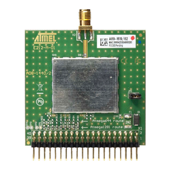
This manual describes the REB212BSMA radio extender board, demonstrating
the high performance at ultra-low power consumption of the Atmel
radio transceiver.
Features
•
High-performance 700/800/900MHz, RF-CMOS AT86RF212B radio transceiver
®
targeted for ZigBee
, IEEE
–
121dB link budget
–
Ultra-low current consumption
–
Ultra-low supply voltage (1.8V to 3.6V)
•
RF reference design and high-performance evaluation platform
•
Interfaces to several of the Atmel microcontroller development platforms
•
Board information EEPROM
–
MAC address
–
Board identification, features, and serial number
–
Crystal calibration values
Atmel-42097B-WIRELESS-AT02876-REB212BSMA-Hardware-User-Manual_ApplicationNote_062014
APPLICATION NOTE
Atmel MCU Wireless
®
802.15.4, 6LoWPAN, and ISM Applications
®
AT86RF212B
Advertisement
Table of Contents

Subscribe to Our Youtube Channel
Related Manuals for Atmel REB212BSMA


Summary of Contents for Atmel REB212BSMA
- Page 1 APPLICATION NOTE AT02876: Atmel REB212BSMA Hardware User Manual Atmel MCU Wireless Introduction This manual describes the REB212BSMA radio extender board, demonstrating ® the high performance at ultra-low power consumption of the Atmel AT86RF212B radio transceiver. Features • High-performance 700/800/900MHz, RF-CMOS AT86RF212B radio transceiver ®...
- Page 2 The REB212BSMA connects directly to the REB controller base board (REB-CBB) [2], or can be used as an RF interface in combination with one of the Atmel microcontroller development platforms. The REB212BSMA together with a microcontroller forms a fully functional wireless node.
-
Page 3: Functional Description
Figure 3-1 shows a development and evaluation setup using the REB controller base board (REB-CBB) in combination with the REB212BSMA radio extender board; via SMA connector which is assembled with quarter wave whip antenna. Figure 3-1. The REB212BSMA Connected to a REB-CBB... -
Page 4: Interface Connector
The REB212BSMA is preconfigured to interface to an STK501 with an Atmel ATmega1281 or a REB-CBB with an Atmel ATxmega 256A3 respectively. To operate the REB212BSMA with an Atmel ATmega644 on STK500, the 0Ω resistors R10 through R18 must be removed and re-installed on the board manually as resistors R20 through R28 (see Appendix Other microcontroller development platforms need to be interfaced using a special adapter board. - Page 5 XT1 (MCLK) n.c. PB7 (SCLK) PB6 (MISO) PB5 (MOSI) PB4 (SEL) PB3 (open) PB2 (RSTN) PB1 (MCLK) PB0 (open) AT02876: Atmel REB212BSMA Hardware User Manual [APPLICATION NOTE] Atmel-42097B-WIRELESS-AT02876-REB212BSMA-Hardware-User-Manual_ApplicationNote_062014...
- Page 6 MAC address for the 802.15.4 node, little endian byte order 0x08 Serial number uint64 Board serial number, little endian byte order 0x10 Board family uint8 Internal board family identifier 0x11 Revision uint8[3] Board revision number ##.##.## AT02876: Atmel REB212BSMA Hardware User Manual [APPLICATION NOTE] Atmel-42097B-WIRELESS-AT02876-REB212BSMA-Hardware-User-Manual_ApplicationNote_062014...
- Page 7 Appendix A). This is required because the Atmel STK500 will provide 5V as default voltage, and the board can also be mounted with reverse polarity. Depending on the actual supply voltage, the diode D1 can consume several milliamperes. This has to be considered when the current consumption of the whole system is measured.
- Page 8 Detailed layout considerations can be found in Section 5.2. The REB212BSMA uses a Siward SX4025 crystal with two load capacitors of 10pF each. To compensate for fabrication and environment variations, the frequency can be further tuned using the radio transceiver register XOSC_CTRL (0x12), refer to [1].
- Page 9 3nH. This is achieved with the connection fan out in between the IC pins and the filter balun combination B1. The trace width is kept small at 0.15mm for a length of approximately 2.5mm. The REB212BSMA is a two-layer FR4 board with a thickness of 1.5mm.
- Page 10 Transceiver Analog GND Routing With the Atmel AT86RF212B, consider pins 3, 6, 27, 30, 31, and 32 as analog ground pins. Pin 7 is an exception and can be connected to the central paddle like the other analog ground pins.
- Page 11 Digital GND Routing and Shielding With the Atmel AT86RF212B, consider pins 12, 16, 18, and 21 as digital ground pins. Digital ground pins are not directly connected to the center paddle. They may carry digital noise from I/O pad cells or other digital processing units within the chip.
-
Page 12: Mechanical Description
Mechanical Description The REB212BSMA is manufactured using a low-cost, two-layer printed circuit board. All components and connectors are mounted on the top side of the board. The format was defined to fit the EXPAND1 connector on the Atmel AVR STK500/STK501 microcontroller evaluation board. -
Page 13: Electrical Characteristics
Condition Minimum Typical Maximum Units Transceiver SLEEP µA Transceiver TRX_OFF, CLKM switched off Supply current (CLKM_CTRL=0) RX_ON BUSY_TX Notes: Board EEPROM standby current. Modulation = OQPSK-250, T output power = +10dBm. AT02876: Atmel REB212BSMA Hardware User Manual [APPLICATION NOTE] Atmel-42097B-WIRELESS-AT02876-REB212BSMA-Hardware-User-Manual_ApplicationNote_062014... - Page 14 [2] AVR2042: REB Controller Base Board – Hardware User Guide; Application Note; Rev. 8334A-AVR-08/10; Atmel Corporation. [3] AT25010B; SPI Serial EEPROM; Datasheet; Rev. 8707CJ SEEPR 6/11; Atmel Corporation. [4] IEEE Std 802.15.4™-2006: Wireless Medium Access Control (MAC) and Physical Layer (PHY) Specifications for Low-Rate Wireless Personal Area Networks (LR-WPANs).
-
Page 15: Appendix A Pcb Design Data
Appendix A PCB Design Data Schematic AT02876: Atmel REB212BSMA Hardware User Manual [APPLICATION NOTE] Atmel-42097B-WIRELESS-AT02876-REB212BSMA-Hardware-User-Manual_ApplicationNote_062014... -
Page 16: Assembly Drawing
PolySwitch resettable fuse 0.2A, miniSMDC020F Raychem miniSMDC020F Jumper cap for 2.54mm pin 3300096 Jumper header Pin header 1x2, 2.54mm THM 1001-121-002 1001-121-002 SMD-Ferrite 220Ω, 100MHz 0603 74279263 Würth 74279263 size Elektronik AT02876: Atmel REB212BSMA Hardware User Manual [APPLICATION NOTE] Atmel-42097B-WIRELESS-AT02876-REB212BSMA-Hardware-User-Manual_ApplicationNote_062014... - Page 17 AT25010B-MAHL-T, 1.8-5V, Ultra Technologies Thin UDFN-8 Dual Inverter ULP-A, NC7WV04P6X_NL Fairchild NC7WV04P6X_NL NC7WV04P6X_NL, SC70-6 2x20 pin header, right angle, 1007-121-040 1007-121-040 2.54mm pitch, through-hole End Launch Jack Receptacle, 142-0711-821 EMERSON 142-0711-821 Round Contact AT02876: Atmel REB212BSMA Hardware User Manual [APPLICATION NOTE] Atmel-42097B-WIRELESS-AT02876-REB212BSMA-Hardware-User-Manual_ApplicationNote_062014...
-
Page 18: Appendix B Radio Certification
Appendix B Radio Certification The REB212BSMA, mounted on a REB controller base board (REB-CBB), has received regulatory approvals for modular devices in the United States and European countries. United States (FCC) B.1.1 Compliance Statement (Part 15.19) The ATREB212BSMA-EK is certified as Limited modular transmitter with FCC ID VW4A091619. The device complies with Part 15 of the FCC rules. - Page 19 The CE marking must be affixed visibly, legibly, and indelibly More detailed information about CE marking requirements you can find at "DIRECTIVE 1999/5/EC OF THE EUROPEAN PARLIAMENT AND OF THE COUNCIL" on 9 March 1999 at section 12. AT02876: Atmel REB212BSMA Hardware User Manual [APPLICATION NOTE] Atmel-42097B-WIRELESS-AT02876-REB212BSMA-Hardware-User-Manual_ApplicationNote_062014...
-
Page 20: Appendix C Revision History
Appendix C Revision History Doc Rev. Date Comments "The ATREB212BSMA-EK is certified as Limited modular transmitter with FCC ID 42097B 06/2014 VW4A091619" is added in B.1.1. New template. 42097A 04/2013 Initial document release. AT02876: Atmel REB212BSMA Hardware User Manual [APPLICATION NOTE] Atmel-42097B-WIRELESS-AT02876-REB212BSMA-Hardware-User-Manual_ApplicationNote_062014... - Page 21 DISCLAIMER: The information in this document is provided in connection with Atmel products. No license, express or implied, by estoppel or otherwise, to any intellectual property right is granted by this document or in connection with the sale of Atmel products. EXCEPT AS SET FORTH IN THE ATMEL TERMS AND CONDITIONS OF SALES LOCATED ON THE ATMEL WEBSITE, ATMEL ASSUMES NO LIABILITY WHATSOEVER AND DISCLAIMS ANY EXPRESS, IMPLIED OR STATUTORY WARRANTY RELATING TO ITS PRODUCTS INCLUDING, BUT NOT LIMITED TO, THE IMPLIED WARRANTY OF MERCHANTABILITY, FITNESS FOR A PARTICULAR PURPOSE, OR NON-INFRINGEMENT.
- Page 22 Mouser Electronics Authorized Distributor Click to View Pricing, Inventory, Delivery & Lifecycle Information: Microchip ATREB212BSMA-EK...
Need help?
Do you have a question about the REB212BSMA and is the answer not in the manual?
Questions and answers