Table of Contents
Advertisement
Repair
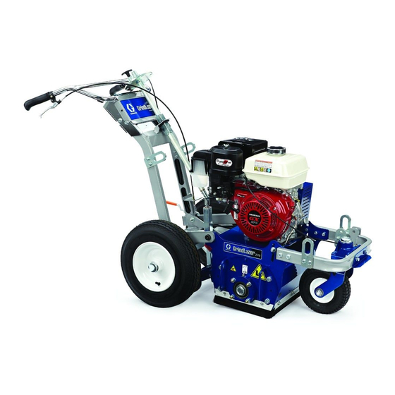
GrindLazer
- Designed to grind flat, horizontal concrete or asphalt surfaces -
Model 571002 - Forward cut
GrindLazer 270 (270 cc / 9 hp)
Model 571003 - Forward cut
GrindLazer 390 (390 cc / 13 hp)
Model 571004 - Reverse up-cut (Must be used with LineDriver
+
GrindLazer 480 (480 cc / 16 hp)
Model 571260 - Reverse up-cut (Must be used with LineDriver
GrindLazer 630 (627 cc / 21 hp)
IMPORTANT SAFETY INSTRUCTIONS
Read all warnings and instructions in this
manual. Save these instructions.
Related Manuals:
Operation - 3A0101
Parts - 3A0103
™
- For removal of materials from concrete and asphalt surfaces -
- Professional outdoor use only -
GrindLazer 270 and 390
(Drums, cutters, and LineDriver ™ sold separately)
™
)
™
)
ti14752b
3A0102D
ti14763a
ti25371a
GrindLazer 630
EN
Advertisement
Table of Contents

Related Manuals for Graco GrindLazer 270


Summary of Contents for Graco GrindLazer 270
- Page 1 - For removal of materials from concrete and asphalt surfaces - - Professional outdoor use only - Model 571002 - Forward cut GrindLazer 270 (270 cc / 9 hp) Model 571003 - Forward cut GrindLazer 390 (390 cc / 13 hp) ™...
-
Page 2: Table Of Contents
Technical Data ......37 Graco Standard Warranty ....39... -
Page 3: Warnings
Warnings Warnings The following warnings are for the setup, use, grounding, maintenance, and repair of this equipment. The exclamation point symbol alerts you to a general warning and the hazard symbol refers to procedure-specific risk. Refer back to these warnings. Additional, product-specific warnings may be found throughout the body of this manual where applicable. - Page 4 Warnings WARNING FIRE AND EXPLOSION HAZARD Flammable fumes, such as solvent and paint fumes, in work area can ignite or explode. To help prevent fire and explosion: • Use equipment only in well ventilated area. • Do not fill fuel tank while engine is running or hot; shut off engine and let it cool. Fuel is flammable and can ignite or explode if spilled on hot surface.
-
Page 5: Component Identification
Component Identification Component Identification 270 and 390 Models 480/630 Models ti14753b Component Description Engine Throttle Lever Adjusts engine speed. Engine Stop Switch Supplies power to Engine Emergency Shut-Off Clamps onto the operator and shuts engine off if cord is disconnected during operation. -
Page 6: Drum Replacement
Drum Replacement Drum Replacement 1. Slide replacement drum onto hex shaft. Avoid touching or handling drum after use until it has completely cooled. Removal ti14766a 1. Remove four bolts and Drum Access Panel (H). 2. Lower Drum Adjustment Dial (D) and pull Drum Engage Lever (E) so drum rests on ground. -
Page 7: Cutter Replacement
Cutter Replacement Cutter Replacement Installation (Carbide Flail/Carbide Miller) 1. Replace cutters and washers (see Cutter Stacking Recommendations, pages 17 - 35). Removal (Carbide Flail/Carbide Miller) 1. Remove drum (see Drum Replacement, page 6). 2. Loosen six bolts on each side of drum (do not remove bolts). - Page 8 Cutter Replacement Removal (Diamond Blades) Installation (Diamond Blades) 1. Remove drum (see Drum Replacement, page 6). 1. Replace all spacers and diamond blades in the sequence and orientation shown below (blades 2. Place drum in vise. should be rotated in alternating segments when stacking).
-
Page 9: Belt Replacement
Belt Replacement Belt Replacement 4. Tighten bottom bolt to lower pulley plate. Removal 1. Remove three nuts and washers. Remove belt shroud. ti15069a 5. Remove used belt. ti15064a 2. Loosen jam nut through two sides of belt. ti15076a ti15085a 3. Use two wrenches to loosen motor mount bolts on each side of scarifier base. - Page 10 Belt Replacement Installation 1. Install new belt. Belt Tension Recommendations: (3VX375 Belt) Model Series Tension (Lbf) 130 +/- 5 174 +/- 6 204 +/- 7 Belt Frequency (Hz) 83 +/- 2 96 +/- 2 104 +/- 2 Used Tension (Lbf) 112 +/- 5 150 +/- 6 176 +/- 7 Belt Frequency (Hz)
-
Page 11: Clutch Replacement
Clutch Replacement Clutch Replacement Installation 1. Install clutch. Removal 1. Remove belt guard and belt (see Belt Replace- ment, page 9). 2. Use impact wrench to remove clutch bolt. ti15148a 2. Use impact wrench to tighten clutch bolt. ti15147a 3. Remove used clutch. ti15059a 3. -
Page 12: Pulley Replacement
Pulley Replacement Pulley Replacement Installation 6. Install pulley onto hex shaft. Removal 1. Remove drum (see Drum Replacement, page 6). 2. Remove belt guard and belt (see Belt Replace- ment, page 9). ti15131a 3. Remove three belt pulley screws and washers. 7. -
Page 13: Brush Replacement
Brush Replacement Brush Replacement Installation 1. Install new brush. Removal 1. Remove two mounting bolts. ti15078b 2. Tighten two mounting bolts. ti15072b 2. Remove used brush. ti15068b ti15078b 3A0102D... -
Page 14: Drive Bearing Assembly Replacement
Drive Bearing Assembly Replacement Drive Bearing Assembly Replacement 2. Install dust cover onto bearing. Hand-tighten nuts and lock washers to the door. NOTE: Do NOT fully tighten bolts at this time. 3. Assemble door onto unit and slide door around until the bearing assembly settles into position for proper Door Bearing Assembly alignment. -
Page 15: Drive Bearing Assembly Removal
Drive Bearing Assembly Replacement Drive Bearing Assembly c. Remove sheave. Removal 1. Remove door from unit and remove any cutting drum on machine. ti14767b ti15126a d. Remove set screw from bushing. ti14765a 2. Remove belt guard and belt (see page 9). 3. -
Page 16: Drive Bearing Assembly Installation
Drive Bearing Assembly Replacement 4. Remove all four nuts holding drive side bearing onto 3. Make sure drive shaft key is assembled as shown cage. below. ti17820a Sheave Installation ti15123b 5. Slide shaft assembly out of holes. 1. Insert bushing onto drive shaft. Make sure key is in place. -
Page 17: Cutter Stacking Recommendations
Cutter Stacking Recommendations Cutter Stacking Recommendations 6 in. (15 cm) Coarse Cut Flail Cutters (Double Space) 276 Spacers / 60 Cutters INSTRUCTIONS: Rotate sequence 180° and repeat for remaining shafts. 13 (S) 15 (S) 1 (C) 2 (S) 1 (C) 1 (C) 2 (S) 2 (S) -
Page 18: In. (20 Cm) Coarse Cut Flail Cutters (Double Space)
Cutter Stacking Recommendations 8 in. (20 cm) Coarse Cut Flail Cutters (Double Space) 234 Spacers / 84 Cutters INSTRUCTIONS: Rotate sequence 180° and repeat for remaining shafts. 5 (S) 8 (S) 1 (C) 2 (S) 1 (C) 1 (C) 2 (S) 2 (S) 1 (C) 1 (C) -
Page 19: In. (25 Cm) Coarse Cut Flail Cutters (Double Space) 210 Spacers / 102 Cutters
Cutter Stacking Recommendations 10 in. (25 cm) Coarse Cut Flail Cutters (Double Space) 210 Spacers / 102 Cutters INSTRUCTIONS: Rotate sequence 180° and repeat for remaining shafts. 1 (S) 3 (S) 1 (C) 2 (S) 1 (C) 1 (C) 2 (S) 2 (S) 1 (C) 1 (C) -
Page 20: In. (15 Cm) General Cut Flail Cutters (Single Space)
Cutter Stacking Recommendations 6 in. (15 cm) General Cut Flail Cutters (Single Space) 234 Spacers / 84 Cutters INSTRUCTIONS: Rotate drum 180° and repeat for remaining shafts. 12 (S) 14 (S) 1 (C) 1 (S) 1 (C) 1 (C) 1 (S) 1 (S) 1 (C) 1 (C) -
Page 21: In. (20 Cm) General Cut Flail Cutters (Single Space) 186 Spacers / 114 Cutters
Cutter Stacking Recommendations 8 in. (20 cm) General Cut Flail Cutters (Single Space) 186 Spacers / 114 Cutters INSTRUCTIONS: Rotate drum 180° and repeat for remaining shafts. 6 (S) 7 (S) 1 (C) 1 (C) 1 (S) 1 (S) 1 (C) 1 (C) 1 (S) 1 (S) -
Page 22: In. (25 Cm) General Cut Flail Cutters (Single Space) 150 Spacers / 138 Cutters
Cutter Stacking Recommendations 10 in. (25 cm) General Cut Flail Cutters (Single Space) 150 Spacers / 138 Cutters INSTRUCTIONS: Rotate drum 180° and repeat for remaining shafts. 1 (S) 1 (C) 1 (S) 1 (C) 1 (S) 1 (C) 1 (S) 1 (C) 1 (S) 1 (C) -
Page 23: In. (15 Cm) Fine Cut Flail Cutters 198 Spacers / 108 Cutters
Cutter Stacking Recommendations 6 in. (15 cm) Fine Cut Flail Cutters 198 Spacers / 108 Cutters INSTRUCTIONS: Rotate sequence 180° and repeat for remaining shafts. 12 (S) 13 (C) 1 (C) 14 (S) 1 (C) 1 (S) 1 (C) 1 (S) 1 (C) 1 (S) 1 (C) -
Page 24: In. (20 Cm) Fine Cut Flail Cutters 138 Spacers / 144 Cutters
Cutter Stacking Recommendations 8 in. (20 cm) Fine Cut Flail Cutters 138 Spacers / 144 Cutters INSTRUCTIONS: Rotate sequence 180° and repeat for remaining shafts. 7 (S) 16 (C) 1 (S) 6 (S) 1 (C) 1 (S) 1 (C) 1 (S) 1 (C) 1 (S) 1 (C) -
Page 25: 10 In. (25 Cm) Fine Cut Flail Cutters
Cutter Stacking Recommendations 10 in. (25 cm) Fine Cut Flail Cutters 90 Spacers / 174 Cutters INSTRUCTIONS: Rotate sequence 180° and repeat for remaining shafts. 1 (S) 1 (S) 16 (C) 1 (C) 1 (S) 1 (S) 1 (C) 1 (S) 1 (C) 1 (S) 1 (C) -
Page 26: In. (15 Cm) Cut Carbide Millers 204 Spacers / 30 Cutters
Cutter Stacking Recommendations 6 in. (15 cm) Cut Carbide Millers 204 Spacers / 30 Cutters INSTRUCTIONS: Rotate sequence 180° and repeat for remaining shafts. 14 (S) 15 (S) 1 (M) 1 (M) 1 (S) 3 (S) 1 (M) 1 (M) 1 (S) 1 (M) 1 (S) -
Page 27: In. (20 Cm) Cut Carbide Millers 132 Spacers / 42 Cutters
Cutter Stacking Recommendations 8 in. (20 cm) Cut Carbide Millers 132 Spacers / 42 Cutters INSTRUCTIONS: Rotate sequence 180° and repeat for remaining shafts. 8 (S) 7 (S) 1 (M) 1 (M) 1 (S) 1 (S) 1 (M) 1 (M) 1 (S) 1 (S) 1 (M) -
Page 28: 10 In. (25 Cm) Cut Carbide Millers
Cutter Stacking Recommendations 10 in. (25 cm) Cut Carbide Millers 66 Spacers / 54 Cutters INSTRUCTIONS: Rotate sequence 180° and repeat for remaining shafts. 1 (S) 1 (S) 1 (M) 1 (M) 1 (S) 1 (S) 1 (M) 1 (M) 1 (S) 1 (S) 1 (M) -
Page 29: In. (15 Cm) Full Cut Flail Setup 258 Spacers / 84 Cutters
Cutter Stacking Recommendations 6 in. (15 cm) Full Cut Flail Setup 258 Spacers / 84 Cutters INSTRUCTIONS: Rotate sequence 180° and repeat for remaining shafts. 13 (S) 15 (S) 1 (C) 1 (S) 1 (C) 1 (C) 1 (S) 1 (S) 1 (C) 1 (C) 1 (S) -
Page 30: In. (20 Cm) Full Cut Flail Setup 210 Spacers / 108 Cutters
Cutter Stacking Recommendations 8 in. (20 cm) Full Cut Flail Setup 210 Spacers / 108 Cutters INSTRUCTIONS: Rotate sequence 180° and repeat for remaining shafts. 7 (S) 9 (S) 1 (C) 1 (S) 1 (S) 1 (C) 1 (C) 1 (S) 1 (S) 1 (C) 1 (C) -
Page 31: In. (25 Cm) Full Cut Flail Setup 162 Spacers / 138 Cutters
Cutter Stacking Recommendations 10 in. (25 cm) Full Cut Flail Setup 162 Spacers / 138 Cutters INSTRUCTIONS: Rotate sequence 180° and repeat for remaining shafts. 1 (S) 2 (S) 1 (C) 1 (C) 1 (S) 1 (S) 1 (C) 1 (C) 1 (S) 1 (S) 1 (C) -
Page 32: In. (15 Cm) Steel Cutters Setup 222 Washers / 126 Cutters
Cutter Stacking Recommendations 6 in. (15 cm) Steel Cutters Setup 222 Washers / 126 Cutters INSTRUCTIONS: Rotate sequence 180° and repeat for remaining shafts. 13 (W) 15 (W) 2 (C) 2 (C) 1 (W) 1 (W) 2 (C) 2 (C) 1 (W) 1 (W) 2 (C) -
Page 33: In. (20 Cm) Steel Cutters Setup 156 Washers / 174 Cutters
Cutter Stacking Recommendations 8 in. (20 cm) Steel Cutters Setup 156 Washers / 174 Cutters INSTRUCTIONS: Rotate sequence 180° and repeat for remaining shafts. 7 (W) 6 (W) 2 (C) 2 (C) 1 (W) 1 (W) 2 (C) 2 (C) 1 (W) 1 (W) 2 (C) -
Page 34: In. (25 Cm) Steel Cutters Setup 114 Washers / 204 Cutters
Cutter Stacking Recommendations 10 in. (25 cm) Steel Cutters Setup 114 Washers / 204 Cutters INSTRUCTIONS: Rotate sequence 180° and repeat for remaining shafts. 1 (W) 2 (W) 1 (C) 1 (W) 2 (C) 2 (C) 1 (W) 1 (W) 2 (C) 2 (C) 1 (W) -
Page 35: Diamond Blades
Cutter Stacking Recommendations Diamond Blades Number of Number of For best performance, use 1/4 in. spacers on each end of Groove Number Steel 1/8 in. Aluminum 1/4 shaft to center diamond blades on drum. Width of Blades Spacers in. Spacers 1 in. -
Page 36: Troubleshooting
Troubleshooting Troubleshooting Problem Cause Solution Engine will not start Engine switch is OFF. Turn engine switch ON. Engine is out of gas. Refill gas tank (see engine manual. Engine oil level is low. Try to start engine. Fill oil is necessary (see engine manual). -
Page 37: Technical Data
Technical Data Technical Data GrindLazer 270 (Model 571002) Dimensions Unpackaged Packaged Height in./cm: 46 (116.8) 50.5 (128.3) Width in./cm: 28 (71.1) 37 (94.0) Length in.cm: 62 (157.5) 73 (185.4) Weight lb/kg: 300 (136) 400 (181) Noise (dBa) Sound Power per ISO 3744: 107.3... - Page 38 Technical Data GrindLazer 630 (Model 571260) Dimensions Unpackaged Packaged Height in./cm: 46 (116.8) 50.5 (128.3) Width in./cm: 28 (71.1) 37 (94.0) Length in.cm: 62 (157.5) 73 (185.4) Weight lb/kg: 338 (153) 438 (199) Noise (dBa) Sound Power per ISO 3744: 108.6 Sound Pressure measured at 3.1 feet (1m): 92.1...
- Page 39 Notes Notes 3A0102D...
-
Page 40: Graco Standard Warranty
With the exception of any special, extended, or limited warranty published by Graco, Graco will, for a period of twelve months from the date of sale, repair or replace any part of the equipment determined by Graco to be defective.
Need help?
Do you have a question about the GrindLazer 270 and is the answer not in the manual?
Questions and answers