Sign In
Upload
Manuals
Brands
Phoenix Contact Manuals
Measuring Instruments
2908307
Phoenix Contact 2908307 Manuals
Manuals and User Guides for Phoenix Contact 2908307. We have
1
Phoenix Contact 2908307 manual available for free PDF download: User Manual
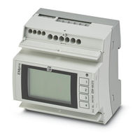
Phoenix Contact 2908307 User Manual (198 pages)
multifunctional energy measuring devices for DIN rail mounting
Brand:
Phoenix Contact
| Category:
Measuring Instruments
| Size: 4.2 MB
Table of Contents
Table of Contents
3
Eem-Mb-370-Pn
2
Table of Contents
3
1 For Your Safety
7
Identification of Warning Notes
7
Qualification of Users
7
Field of Application of the Product
8
Intended Use
8
Product Changes
8
Safety Notes
8
2 Device Description
9
Grid Type
10
Product Overview
13
3 Mounting and Installation
15
Mounting
15
Installation
16
Pin Assignment
17
Pin Assignment Example
17
Figure 11-4
17
Supply
19
Grid Types
20
One-Phase Network, Two Conductors, One Current Transformer
20
Two-Phase Network, Two Conductors, One Current Transformer
20
Three-Phase Network, Three Conductors, One Current Transform
21
Three-Phase Network, Three Conductors, Two Current Transform
21
Three-Phase Network, Three Conductors, Three Current Transform
21
Three-Phase Network, Four Conductors, One Current Transformer
21
Table 11-3
21
Three-Phase Network, Four Conductors, Three Current Transform
22
Two-Phase Network, Three Conductors, Two Current Transformers
22
Table 4-2
22
One-Phase Network, Two Conductors, One Rogowski Coil
23
Two-Phase Network, Two Conductors, One Rogowski Coil
23
Three-Phase Network, Three Conductors, One Rogowski Coil
23
Table 4-1
23
Table 11-2
23
Three-Phase Network, Three Conductors, Three Rogowski Coils
24
Three-Phase Network, Four Conductors, One Rogowski Coil
24
Three-Phase Network, Four Conductors, Three Rogowski Coils
24
Two-Phase Network, Three Conductors, Two Rogowski Coils
24
4 Operating and Indication Elements
25
Energy Measuring Device with Display
25
Energy Measuring Device Without Display
25
Energy Measuring Device Without Display, with Additional PROFINET Interface
26
Eem-Mb-370
26
Energy Measuring Device Without Display, with Additional Ethernet/Ip Interface
27
Eem-Mb370-Eip
27
Technical Data of the Display
28
Displaying the Events
29
Operating Elements on the Display (Softkeys)
30
5 Basic Device Configuration
31
Basic Device Configuration Via the Display
31
Step 1: Language Selection
31
Step 2: Network Settings
32
Step 3: Ipv4
32
Step 4: Grid Type
33
Selection of Grid Type with Current Transformers
33
Selection of Grid Type with Rogowski Coils
33
Step 5A: Current Input (Energy Measuring Device with Current Transformer)
34
Current Input
34
Step 5B: Current Input (Energy Measuring Device with Rogowski Coil)
35
Step 6: Voltage Input
35
Step 7: Configuration Overview
36
Step 8: Setting a Personal PIN
36
Step 9: Activating the PIN
36
Basic Device Configuration Via the Web Server
37
Step 1: Network Settings
38
Step 2: Selecting the Grid Type
39
Step 3: Configuration of the Current Input (Current Transformer)
40
Step 3: Configuration of the Current Input (Rogowski Coil)
41
Step 4: Voltage Input
43
Optional: Voltage Transducer
44
Step 5: Configuration Overview
45
Configuration Overview
45
6 Navigation Structure and Display
47
Menu Structure on the Display
47
Menu Structure on the Web Server
48
7 Device Settings and Information
51
Selecting the Language
51
Language" Menu
51
Date and Time
52
Reading the Date and Time
52
Date / Time" Menu
52
Settings: "Date / Time
52
Setting the Date and Time Manually
53
Synchronizing the Date and Time with an SNTP Server
54
Menu: "Settings, Date / Time, Settings, "SNTP Server"" Mode
54
Time Zones
55
Summer Time Rule
57
Menu: "Settings, Date / Time, Settings, Summer Time Rule
57
Adjusting the Display (Contract, Brightness, Illumination Time of Backlight)
58
Adjusting the Contrast of the Display
58
Settings: "Display, Contrast
58
Adjusting the Brightness of the Display
59
Figure 7-11 Settings: "Display, Brightness
59
Adjusting the Illumination Time of the Backlight
60
Figure 7-12 Menu: "Display, Permanent Light
60
Figure 7-13 Settings: "Display, Permanent Light
60
Figure 7-14: Settings: "Illumination Time
61
Selecting the Format of the Standard Display (IEC or IEEE)
62
Figure 7-15 Menu: "Display, Standard Display
62
Figure 7-16 Settings: "Display, Standard Display
62
Activating Color Change for Alarm
63
Figure 7-17 Menu: "Display, Alarm Light
63
Figure 7-18 Settings: "Display, Alarm Light
63
Selecting the Refresh Time for Displaying Measured Values
64
Figure 7-19 Menu: "Display, Refresh Time
64
Figure 7-20 Settings: "Display, Refresh Time
64
Adjusting the Display Via the Web Server
65
Figure 7-21: Web Server: "Settings, Display
65
Device Information
66
Figure 7-22 Menu: "Device Info
66
Figure 7-23 Display: "Device Info
66
Resetting the Device to Default Settings
67
Figure 7-24 Menu: "System, Factory Reset
67
Figure 7-25 Menu: "System, Factory Reset
67
Figure 0-1: Settings: "Illumination Time
69
8 Configuration
71
Access and Passwords
72
Editing Access Data Via the Display
72
Figure 8-1: Menu: "System, PIN XXXX
72
Figure 8-2: Settings: "System, PIN XXXX
72
Editing Access Data Via the Web Server
73
Figure 8-3: Menu: "System, User Management, Change Password
73
Deactivating the Configuration Via the Display
74
Figure 8-4: Menu: "Settings, Display
74
Deactivating the Modbus Communication Interface
75
Figure 8-5 Menu: "System, PIN Active/Wbm Active
75
Figure 8-6 Setting: "System, WBM Active
75
Figure 8-7 Setting: "System, PIN Active
75
Transferring Configuration Data
77
Exporting Configuration Data
77
Figure 8-8: Menu: "System, Configuration Data, Export Configuration
77
Importing Configuration Data
78
Figure 8-9: Menu: "System, Configuration Data, Import Configuration
78
Direct Transfer of Configuration Data
79
Figure 8-10 Menu: "System, Configuration Data, Transfer Configuration
79
9 Measuring Technology
81
Meter Readings
81
Figure 9-1: Menu: "Home, Meter Readings
81
Energy Meters
82
Figure 9-2 Menu: "E, Energy Total
82
Figure 9-3 Menu: "E, Energy Total
82
Energy Resettable
83
Figure 9-4: Menu: "E, Energy Resettable
83
Figure 9-5: Menu: "E, Energy Resettable
83
Tariff Meter
84
Figure 9-6: Menu: "Tar, Tariff Meter 1
84
Figure 9-7: Menu: "Tar, Tariff Meter 1
84
Operating Hours Counter
85
Figure 9-8 Menu: "Device Info, Operating Hours/Load Operation
85
Figure 9-9 Menu: "Device Info, Operating Hours/Load Operation
85
Statistics
86
Average Values
86
Figure 9-10: Menu: "Settings, Average Values
87
Figure 9-11 Menu: "Average Values, Settings
88
Figure 9-12 AVG over Fixed Interval (Fixed Block)
89
Figure 9-13 Sliding Average Value (Sliding Block)
89
Figure 9-14 Rolling Average Value (Rolling Block)
90
Figure 9-15: Prediction Calculation (Equally Weighted Average)
91
Figure 9-16: Prediction Generation (Weighted Average)
91
10 Functions
93
Digital Input
93
Figure 10-1 Digital Input
94
Impulse Counter
95
Figure 10-2: Menu: "Settings, Impulse Counter
95
Tariff Selection
97
Figure 10-3 Menu: "Settings, Tariffs, Digital Input
97
Synchronization of Average Values
99
Figure 10-4 Menu: "UL-L
99
Figure 10-5 Menu: "UL-L, UL-L Instantaneous" (Instantaneous Values, Instantaneous)
99
Figure 10-6 Menu: "UL-L, UL-L Min" (Min. Values, Min)
99
Figure 10-7 Menu: "UL-L, UL-L Max" (Max. Values, Max)
99
Figure 10-8 Menu: "UL-L, UL-L AVG Min" (Minimum Average Values, AVG Min)
100
Figure 10-9 Menu: "UL-L, UL-L AVG" (Average Values, AVG)
100
Figure 10-10 Menu: "UL-L, UL-L AVG Max" (Max. Average Values, AVG Max)
100
Acknowledgment of Alarms
101
Figure 10-11: Menu: "Settings, Average Values, Status
101
Digital Output
102
Figure 10-12: Menu: "Settings, Digital Output
102
Impulse
104
Figure 10-13 Menu: "Settings, Digital Output", "Impulse" Function
104
Device State
106
Figure 10-14: Menu: "Settings, Digital Output", "Device State" Function
106
Manually
108
Figure 10-15: Menu: "Settings, Digital Output", "Manually" Function
108
Alarm
109
Figure 10-16 Menu: "Settings, Digital Output", "Alarm" Function
110
Figure 10-17: Menu: "Settings, Alarm, Status
111
Figure 10-18: Menu: "Settings, Alarm
112
Rotary Field Direction
114
Figure 10-19 Menu: "Digital Output, Settings, "Rotary Field Direction
114
Deactivating the Digital Output
116
Figure 10-20: Menu: "Digital Output, Settings", "Deactivated" Function
116
Tariff Selection
118
Figure 10-21 Menu: "Tar, Tariff Meter
118
Figure 10-22: Menu: "Tar, Tariff Meter 1
118
Tariff Selection Via the Communication Interface
119
Figure 10-23: Menu: "Tariffs, Settings
119
Tariff Selection Using a Time Schedule
120
Figure 10-24: Menu: "Tariffs, Settings
121
Logic Gate
123
Figure 10-25 Menu: "Settings, Digital Output", "Alarm" Function
124
Figure 10-26: Logic Gate with and Operator
125
Figure 10-27: Logic Gate with NAND Operator
125
Figure 10-28 Logic Gate with or Operator
126
Figure 10-29 Logic Gate with nor Operator
126
Figure 10-30 Logic Gate with XOR Operator
126
Figure 10-31 Logic Gate with NXOR Operator
127
Data Logging
128
Figure 10-32 Menu: "Logging
128
Figure 10-33: "Menu: Logging, Settings
129
Figure 10-34 Menu: "Logging, Saved Data
130
Firmware Update
131
Execution
131
Figure 10-35 Execution of a Firmware Update
131
Figure 10-36 Progress and State
132
Security
133
11 Communication
135
Ethernet
138
IP Addressing
138
Configuration of the Communication Interface
139
Status of the Communication Interface
140
Security
140
Modbus
140
Function
140
Modbus/Rtu
141
Figure 11-5 Topology
141
Figure 11-6 Connections and Designations
142
Figure 11-7 Modbus Status
143
Figure 11-8 Modbus Settings
144
Modbus/Tcp
145
Modbus Gateway
145
Profinet
147
Software
147
Preparing the GSDML File
147
Integrating the GSDML File
147
Figure 11-9 "Options, Manage General Station Description Files (GSD)
147
Figure 11-1
148
Figure 11-10: Installing the Station Description File
148
Figure 11-11: Dialog: "Manage General Station Description Files
149
Integrating Hardware
150
Figure 11-12: "Devices & Networks" in the Network View
150
Figure 11-13: Selecting the Empro from the Hardware Catalog
151
Figure 11-14: Adding Empro to Network View
152
Figure 11-15: Empro in the Network View
153
Figure 11-16: Assigning an I/O Controller to the Empro
154
Figure 11-17: Selecting the I/O Controller
154
Figure 11-18: Networking Controller and Energy Measurement Device
155
Integrating Modules and Submodules
156
Figure 11-19: Adding a Module to the Device Overview
156
Figure 11-2
157
Figure 11-20: Submodules in the Hardware Catalog
157
Figure 11-21: Inserting Submodules
158
Figure 11-22: Available Modules and Submodules
159
Figure 11-23: Selecting a Submodule in the Device Overview
160
Linking Process Data
161
Assigning a Device Name
162
Function Check
167
Figure 11-3
167
Configuration
168
Modbus/Rtu
168
Modbus/Tcp
168
Modbus Gateway
168
Safety
169
Data Types and Registers
170
Register Table
172
Contents of the Register Table
172
Description of the Register Table
172
12 Technical Data
177
A Appendix For Document Lists
181
List of Figures
181
A 2 List of Tables
187
Index
189
Advertisement
Advertisement
Related Products
Phoenix Contact 2908308
Phoenix Contact 2907983
Phoenix Contact 2907985
Phoenix Contact 2907976
Phoenix Contact 2901363
Phoenix Contact 2903805
Phoenix Contact 2903807
Phoenix Contact 2903806
Phoenix Contact 2903808
Phoenix Contact 2901535
Phoenix Contact Categories
Switch
Controller
Power Supply
Industrial Equipment
Control Unit
More Phoenix Contact Manuals
Login
Sign In
OR
Sign in with Facebook
Sign in with Google
Upload manual
Upload from disk
Upload from URL