Advertisement
Table of Contents
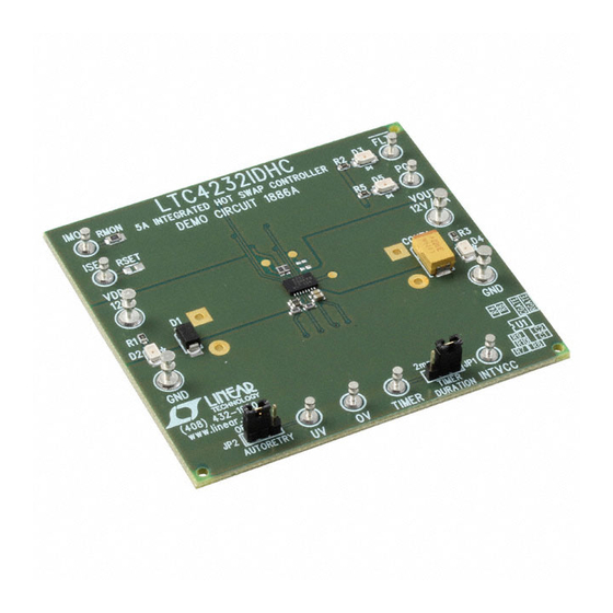
Description
Demonstration circuit 1886A features the LTC4232 5A
Integrated Hot Swap™ Controller. The LTC4232 is ideally
suited for demanding power distribution control in 2.9V
to 15V applications for hot board insertion protection,
high side power switching, and electronic circuit breaker
functions. The LTC4232 provides a rich set of features to
support Hot Swap applications including:
• 2% accurate undervoltage and overvoltage protection
• Overtemperature protection
• Adjustable inrush current control
• Adjustable, 10% accurate current limit with program-
mable cutout time
performance summary
SYMBOL
PARAMETER
V
Input Supply Range
DD
dVGATE/dt
GATE Pin Turn-On Ramp Rate
MOSFET + Sense Resistor On-Resistance
R
ON
I
Current Limit Threshold
LIM(TH)
I
Current Limit Threshold
LIM(TH)
V
OV, UV, FB Pin Threshold Voltage
TH
V
UV Pin Reset Threshold Voltage
UV(RTH)
V
FB Pin Power Good Hysteresis
FB(HYST)
V
TIMER Pin High Threshold
TIMER(H)
V
TIMER Pin Low Threshold
TIMER(L)
I
TIMER Pin Pull-Up Current
TIMER(UP)
I
TIMER Pin Pulldown Current
TIMER(DN)
I
Gate Pull-Up Current
GATE(UP)
t
Auto-Retry Turn-On Delay
D(AUTO-RET)
DEMO MANUAL DC1886A
• Programmable output voltage ramp rate
• Configurable for auto-retry or latchoff on overcurrent
faults
• Power good and fault outputs
Available in a 16-lead 5mm × 3mm DFN package, the
LTC4232 is showcased on demonstration circuit 1886A,
configured for a 12V application. By changing a few pas-
sive components, 2.9V to 15V applications can easily be
evaluated.
Design files for this circuit board are available at
http://www.linear.com/demo
L, LT, LTC, LTM, Linear Technology and the Linear logo are registered trademarks and
Hot Swap is a trademark of Linear Technology Corporation. All other trademarks are the
property of their respective owners.
(T
= 25°C)
A
CONDITIONS
V
= 1.23V
FB
V
= 0V
FB
V
= 1.23V, R
= 20k
FB
SET
V
Rising
IN
V
Falling
UV
V
Rising
TIMER
V
Falling
TIMER
V
= 0
TIMER
V
= 1.2V
TIMER
Gate Drive On, V
= V
GATE
5A Integrated
Hot Swap Controller
MIN
TYP
2.9
0.15
0.3
15
33
5.0
5.6
1.2
1.5
2.6
2.9
1.21
1.235
0.55
0.62
10
20
1.2
1.235
0.1
0.21
–80
–100
1.4
2
= 12V
–18
–14
OUT
50
100
LTC4232:
MAX
UNITS
15
V
0.55
V/ms
50
mΩ
6.1
A
1.8
A
3.3
A
1.26
V
0.7
V
30
mV
1.28
V
0.3
V
–120
µA
2.6
µA
–29
µA
150
ms
dc1886af
1
Advertisement
Table of Contents

Subscribe to Our Youtube Channel
Related Manuals for Linear Technology DC1886A


Summary of Contents for Linear Technology DC1886A
- Page 1 • Adjustable, 10% accurate current limit with program- http://www.linear.com/demo mable cutout time L, LT, LTC, LTM, Linear Technology and the Linear logo are registered trademarks and Hot Swap is a trademark of Linear Technology Corporation. All other trademarks are the property of their respective owners. performance summary = 25°C)
-
Page 2: Quick Start Procedure
DEMO MANUAL DC1886A Quick start proceDure Demonstration circuit 1886A is easy to set up to evalu- Demonstration Circuit 1886A has two user configurable ate the performance of the LTC4232. Refer to Figure 1 jumper options: for proper measurement equipment setup and follow the • JP1 TIMER DURATION: Set to 2ms for the internal 2ms... - Page 3 DEMO MANUAL DC1886A Quick start proceDure LEDs indicate the state of input power, output power, FAULT respectively) and both D3 (FLT) and D5 (PG) should be and PG. Load current can be monitored on the I turret, off. On power-up, observe the slope of V . This should which has a gain of 0.4V/A determined by R (20k). be in the range of 0.15 to 0.55V/ms, corresponding to a ramp-up time of 22ms to 80ms to 12V. With the circuit Set an adjustable power supply capable of supplying 10A functioning, additional evaluations can now be performed. to 12V. Turn off power and connect the supply to the V and GND turrets.
- Page 4 DEMO MANUAL DC1886A Quick start proceDure Inrush into capacitive load: One of the main functions of Thus, the circuit will always power up successfully with a a hot swap circuit is to provide controlled ramp-up into a , and observation of the TIMER 2000µF capacitor at V capacitive load to avoid disturbing the input power supply.
- Page 5 FB rises above approximately 100mV the current (and DC1886A, add additional bulk capacitance across the V hence the output ramp rate) increases, however the timer and GND turrets. This capacitance may also be needed if expires before the output reaches its final value.
- Page 6 DEMO MANUAL DC1886A schematic Diagram dc1886af...
-
Page 7: Parts List
Information furnished by Linear Technology Corporation is believed to be accurate and reliable. However, no responsibility is assumed for its use. Linear Technology Corporation makes no representa- tion that the interconnection of its circuits as described herein will not infringe on existing patent rights. - Page 8 DEMO MANUAL DC1886A DEMONSTRATION BOARD IMPORTANT NOTICE Linear Technology Corporation (LTC) provides the enclosed product(s) under the following AS IS conditions: This demonstration board (DEMO BOARD) kit being sold or provided by Linear Technology is intended for use for ENGINEERING DEVELOPMENT OR EVALUATION PURPOSES ONLY and is not provided by LTC for commercial use. As such, the DEMO BOARD herein may not be complete in terms of required design-, marketing-, and/or manufacturing-related protective considerations, including but not limited to product safety measures typically found in finished commercial goods. As a prototype, this product does not fall within the scope of the European Union...
Need help?
Do you have a question about the DC1886A and is the answer not in the manual?
Questions and answers