Table of Contents
Advertisement
Quick Links
Advertisement
Table of Contents

Related Manuals for ECS 865GV-M Deluxe


Summary of Contents for ECS 865GV-M Deluxe
- Page 3 Copyright Preface This publication, including all photographs, illustrations and software, is protected under international copyright laws, with all rights reserved. Neither this manual, nor any of the material contained herein, may be reproduced without written consent of the author. Version 5.0 Disclaimer The information in this document is subject to change without notice.
- Page 4 ii ii Shielded interconnect cables and a shielded AC power cable must be employed with this equipment to ensure compliance with the pertinent RF emission limits governing this device. Changes or modifications not expressly approved by the system’s manufacturer could void the user’s authority to operate the equipment.
-
Page 5: Table Of Contents
T T T T T ABLE OF CONTENTS ABLE OF CONTENTS ABLE OF CONTENTS ABLE OF CONTENTS ABLE OF CONTENTS Preface Chapter 1 Introducing the Motherboard Introduction..........................................1 Feature..........................................2 Motherboard Components....................................4 Chapter2 Installing the Motherboard Safety Precautions.........................................5 Choosing a Computer Case....................................5 Installing the Motherboard in a Case.................................5 Checking Jumper Settings....................................6 Setting Jumpers........................................6... - Page 6 Installing Add-on Cards....................................13 Connecting Optional Devices....................................14 Connecting I/O Devices....................................16 Chapter 3 Using BIOS About the Setup Utility.......................................17 The Standard Configuration....................................17 Entering the Setup Utility....................................17 Updating the BIOS.......................................18 Using BIOS..........................................19 Standard CMOS Features.....................................19 Advanced BIOS Features.....................................20 Advanced Chipset Features......................................23 Integrated Peripherals......................................24 Power Management Setup.....................................28 PNP/PCI Configurations.......................................30 PC Health Status........................................31...
- Page 7 Chapter 4 Using the Motherboard Software About the Software CD-ROM...................................35 Auto-installing under Windows 98/ME/2000/XP...............................35 Running Setup........................................36 Manual Installation....................................37 Utility Software Reference....................................37 Multi-Language Translation...
-
Page 8: Introducing The Motherboard
Chapter 1 Introducing the Motherboard Introduction Thank you for choosing 865GV-M Deluxe motherboard of great perfor- There is an advanced full set of I/O ports in the rear panel, including PS/2 mance and with enhanced function. 865GV-M Deluxe motherboard carries mouse and keyboard connectors, COM1, LPT1, VGA port, and four USB a micro-ATX form factor of 244 x 244 mm. -
Page 9: Feature
100/66/33, BMIDE and PIO modes Processor • Compliant with PCI 2.3 specificaiton at 33 MHz 865GV-M Deluxe uses a mPGA 478-pin socket that carries the following • Integrated Serial ATA Host Controllers, supporting data transfer rates up to 1.5Gb/s features: •... - Page 10 Graphics Integrated I/O • Embedded Intel Extreme Graphics II The motherboard has a full set of I/O ports and connectors: • 3D setup and render engine • Two PS/2 ports for mouse and keyboard • 2D/3D graphics enhancement • One serial port •...
-
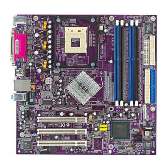
Page 11: Motherboard Components
Motherboard Components Table of Motherboard Components LABEL COMPONENT 1 CPU Socket mPGA478 socket for Pentium 4 CPUs 2 PWRFAN1 Power fan connector 3 CPUFAN1 CPU cooling fan connector 4 DIMM1~DIMM4 184-pin DDR SDRAM slots 5 IR1 Infrared header 6 ATX1 Standard 20-pin ATX power connector 7 FDD1 Floppy disk drive connector... -
Page 12: Chapter2
Chapter 2 Installing the Motherboard Safety Precautions Installing the Motherboard in a Case • Refer to the following illustration and instructions for installing the Follow these safety precautions when installing the motherboard in a case: motherboard • Wear a grounding strap attached to a grounded device to avoid This illustration shows an example of a motherboard being installed in a tower-type case: damage from static electricity... -
Page 13: Checking Jumper Settings
Checking Jumper Settings Checking Jumper Settings This section explains how to set jumpers for correct configuration of the The following illustration shows the location of the motherboard jumpers. motherboard. Pin 1 is labeled. Setting Jumpers Use the motherboard jumpers to set system configuration options. Jumpers with more than one pin are numbered. -
Page 14: Jumper Settings
Jumper Settings Connecting a Case Components After you have installed the motherboard into a case, you can begin con- Jumper Description Setting (default) necting the motherboard components. Refer to the following: 1-2: Normal 3-pin CLEAR CMOS 1. Connect the CPU cooling fan cable to CPUFAN1. 2-3: Clear 2. -
Page 15: Front Panel Header
SPK1: Internal speaker ATX12V: ATX 12V Power Connector Signal Name Signal Name Signal Ground Buzzer Ground +12V +12V SJ1: Single-color LED header Front Panel Header Signal Name The front panel header (PANEL1) provides a standard set of switch and ACPI LED Signal Name LED headers commonly found on ATX or micro-ATX cases. -
Page 16: Installing Hardware
Hard Drive Activity LED Installing Hardware Connecting pins 1 and 3 to a front panel mounted LED provides visual Installing the Processor indication that data is being read from or written to the hard drive. For the LED to function properly, an IDE drive should be connected to the onboard Caution: When installing a CPU heatsink and cooling fan IDE interface. -
Page 17: Installing Memory Modules
Installing Memory Modules processor, consider the performance requirements of the system. Perfor- 865GV-M Deluxe accommodates four 184-pin 2.5V unbuffered Double Data mance is based on the processor design, the clock speed and system bus Rate (DDR) SDRAM (Synchronous Dynamic Random Access Memory) frequency of the processor, and the quantity of internal cache memory and memory modules, supporting Dual-channel DDR memory(128-bit wide). -
Page 18: Installing A Hard Disk Drive/Cd-Rom/Sata Hard Drive
Installing a Hard Dish Drive/CD-ROM/SATA Hard Install any remaining DIMM modules. Drive This section describes how to install IDE devices such as a hard disk drive and a CD-ROM drive. About IDE Devices Your motherboard has a primary and secondary IDE channel interface (IDE1 Table A: DDR (memory module) QVL (Qualified Vendor List) and IDE2). -
Page 19: Installing A Floppy Diskette Drive
IDE devices enclose jumpers or switches used to set the IDE device as 4. Attach the SATA power cable to the SATA hard drive and connect MASTER or SLAVE. Refer to the IDE device user’s manual. Installing two the other end to the power supply. IDE devices on one cable, ensure that one device is set to MASTER and the other device is set to SLAVE. -
Page 20: Installing Add-On Cards
3. Secure the metal bracket of the card to the system case with a screw. PCI Slot 865GV-M Deluxe is equipped with three standard PCI slots. For some add-on cards, for example graphics adapters and PCI stands for Peripheral Component Interconnect and is a... -
Page 21: Connecting Optional Devices
AUDIO1: Front Panel Audio header Connecting Optional Devices This header allows the user to install auxiliary front-oriented microphone Refer to the following for information on connecting the motherboard’s and line-out ports for easier access. optional devices: Signal Name Function AUD_MIC Front Panel Microphone input signal AUD_GND Ground used by Analog Audio Circuits... - Page 22 USB3/USB4: Front Panel USB header IR1: Infrared port The motherboard has four USB ports installed on the rear edge I/O port The motherboard supports an Infrared (IR1) data port. Infrared ports allow array. Additionally, some computer cases have USB ports at the front of the the wireless exchange of information between your computer and similarly case.
-
Page 23: Connecting I/O Devices
Connecting I/O Devices The backplane of the motherboard has the following I/O ports: PS2 Mouse Use the upper PS/2 port to connect a PS/2 pointing device. PS2 Keyboard Use the lower PS/2 port to connect a PS/2 key board. Parallel Port (LPT1) Use LPT1 to connect printers or other parallel communications devices. -
Page 24: Using Bios
17 17 17 17 17 Chapter 3 Using BIOS About the Setup Utility The Standard Configuration The computer uses the latest Award BIOS with support for Windows Plug and A standard configuration has already been set in the Setup Utility. Play. -
Page 25: Updating The Bios
18 18 18 18 18 Press DEL to enter SETUP Updating the BIOS Pressing the delete key accesses the BIOS Setup Utility: You can download and install updated BIOS for this motherboard from the Phoenix-AwardBIOS CMOS Setup Utility: manufacturer’s Web site. New BIOS provides support for new peripherals, improvements in performance, or fixes for known bugs. -
Page 26: Using Bios
19 19 19 19 19 Using BIOS Date and Time The Date and Time items show the current date and time on the computer. If When you start the Setup Utility, the main menu appears. The main menu of you are running a Windows OS, these items are automatically updated whenever the Setup Utility displays a list of the options that are available. -
Page 27: Advanced Bios Features
20 20 20 20 IDE Channel 0/1 Master/Slave (Auto) Halt On (All Errors) Leave this item at Auto to enable the system to automatically detect and This item defines the operation of the system POST (Power On Self configure IDE devices on the channel. If it fails to find a device, change the Test) routine. - Page 28 21 21 21 21 21 CPU Feature (Press Enter) Hard Disk Boot Priority (Press Enter) Scroll to this item and press <Enter> to view the following screen: Scroll to this item and press <Enter> to view the following screen: Phoenix-AwardBIOS CMOS Setup Utility Phoenix-AwardBIOS CMOS Setup Utility CPU Feature Hard Disk Boot Priority...
- Page 29 22 22 22 22 22 Swap Floppy Drive (Disabled) Security Option (Setup) If you have two floppy diskette drives in your system, this item allows you If you have installed password protection, this item defines if the password to swap the assigned drive letters so that drive A becomes drive B, and drive is required at system start up, or if it is only required when a user tries to B becomes drive A.
-
Page 30: Advanced Chipset Features
23 23 23 23 Advanced Chipset Features • CAS Latency Time (2): When synchronous DRAM is installed, the number of clock cycles of CAS latency depends These items define critical timing parameters of the motherboard. You on the DRAM timing. Do not reset this field from the default should leave the items on this page at their default values unless you are value specified by the system designer. -
Page 31: Integrated Peripherals
24 24 24 24 24 Init Display First (PCI Slot) Phoenix-AwardBIOS CMOS Setup Utility Integrated Peripherals Use this item to specify whether your graphics adapter is installed in one of the PCI slots or is integrated on the motherboard. OnChip IDE Device [Press Enter] Item Help Fast Chip Select (Auto) - Page 32 25 25 25 25 Press <Esc> to return to the Integrated Peripherals page. IDE HDD Block Mode (Enabled) Block mode is also called block transfer, multiple commands, or multiple Onboard Device (Press Enter) sector read/write. If your IDE hard drive supports block mode (most new drives do), select Enabled for automatic detection of the optimal number Scroll to this item and press <Enter>...
- Page 33 26 26 26 26 SuperIO Device (Press Enter) USB Mouse Support (Disabled) Enable this item if you plan to use a mouse connected through the USB Scroll to this item and press <Enter> to view the following screen: port in a legacy operating system (such as DOS) that does not support Plug Phoenix-AwardBIOS CMOS Setup Utility and Play.
- Page 34 27 27 27 27 27 Onboard Serial Port 1 (3F8/IRQ4) Onboard Parallel Port (378/IRQ7) This option is used to assign the I/O address and interrupt request (IRQ) This option is used to assign the I/O address and interrupt request (IRQ) for onboard serial port 1 (COM1).
-
Page 35: Power Management Setup
28 28 28 28 Power Management Setup ACPI Suspend Type (S3(STR)) Use this item to define how your system suspends. In the default, S3 This option lets you control system power management. The system has (STR), the suspend mode is a suspend to RAM, i.e., the system shuts down various power-saving modes including powering down the hard disk, with the exception of a refresh current to the system memory. - Page 36 29 29 29 29 Soft-Off by PWR-BTTN (Instant-Off) channels 0 or 1. Under ACPI (Advanced Configuration and Power management Interface) FDD, COM, LPT Port (Disabled) you can create a software power down. In a software power down, the When this item is enabled, the system will restart the power-saving system can be resumed by Wake Up Alarms.
-
Page 37: Pnp/Pci Configurations
PNP/PCI Configurations If you cannot get a legacy ISA (Industry Standard Architecture) expansion card to work properly, you might be able to solve the problem by changing These options configure how PnP (Plug and Play) and PCI expansion this item to Manual, and then opening up the IRQ Resources submenu. cards operate in your system. -
Page 38: Pc Health Status
31 31 31 31 31 Target Temperature (Disabled) PCI/VGA Palette Snoop (Disabled) This item enables throttling when CPU targets the temperature. This item is designed to overcome problems that can be caused by some Shutdown Temperature (Disabled) non-standard VGA cards. This board includes a built-in VGA system that does not require palette snooping so you must leave this item disabled. -
Page 39: Frequency Control
32 32 32 32 Frequency Control Auto Detect PCI Clk (Enabled) When this item is enabled, BIOS will disable the clock signal of free This item enables you to set the clock speed and system bus for your DIMM and PCI slots. system. -
Page 40: Load Fail-Safe Defaults
33 33 Load Fail-Safe Defaults Option Set Supervisor/User Password This option opens a dialog box that lets you install fail-safe defaults for When this function is selected, the following message appears at the all appropriate items in the Setup Utility: center of the screen to assist you in creating a password. -
Page 41: Save & Exit Setup
34 34 34 34 Save & Exit Setup Option Highlight this item and press <Enter> to save the changes that you have made in the Setup Utility and exit the Setup Utility. When the Save and Exit dialog box appears, press <Y> to save and exit, or press <N> to return to the main menu: Exit Without Saving Highlight this item and press <Enter>... -
Page 42: Using The Motherboard Software
35 35 35 35 Chapter 4 Using the Motherboard Software About the Software CD-ROM The support software CD-ROM that is included in the motherboard package con- tains all the drivers and utility programs needed to properly run the bundled prod- ucts. -
Page 43: Running Setup
36 36 36 36 Application Tab Click Next. The following screen appears: Lists the software utilities that are available on the CD. Read Me Tab Displays the path for all software and drivers available on the CD. Running Setup Follow these instructions to install device drivers and software for the motherboard: Click Setup. -
Page 44: Manual Installation
37 37 37 37 37 Manual Installation WinFlash Utility Insert the CD in the CD-ROM drive and locate the PATH.DOC file in the root The Award WinFlash utility is a Windows version of the DOS Award BIOS directory. This file contains the information needed to locate the drivers for your flash writer utility.
Need help?
Do you have a question about the 865GV-M Deluxe and is the answer not in the manual?
Questions and answers