Table of Contents
Advertisement
Available languages
Available languages
Advertisement
Table of Contents

Related Manuals for ECS 865G-M8


Summary of Contents for ECS 865G-M8
- Page 3 Preface Copyright This publication, including all photographs, illustrations and software, is protected under international copyright laws, with all rights reserved. Neither this manual, nor any of the material contained herein, may be reproduced without written consent of the author. Version 1.0 Disclaimer The information in this document is subject to change without notice.
-
Page 4: Declaration Of Conformity
Declaration of Conformity This device complies with part 15 of the FCC rules. Operation is subject to the following conditions: • This device may not cause harmful interference, and • This device must accept any interference received, including interference that may cause undesired operation. -
Page 5: Table Of Contents
T T T T T ABLE OF CONTENTS ABLE OF CONTENTS ABLE OF CONTENTS ABLE OF CONTENTS ABLE OF CONTENTS Preface Chapter 1 Introducing the Motherboard Introduction....................1 Feature......................2 Motherboard Components................4 7 7 7 7 7 Chapter 2 Installing the Motherboard Safety Precautions..................7 Choosing a Computer Case...............7 Installing the Motherboard in a Case............7... - Page 6 Advanced BIOS Features.............30 Advanced Chipset Features............34 Integrated Peripherals..............36 Power Management Setup............41 PNP/PCI Configurations.............43 PC Health Status................44 Frequency Control...............45 Load Fail-Safe Settings..............46 Load Optimized Defaults.............46 Set Supervisor/User Password............46 Save & Exit Setup ................47 Exit Without Saving..............47 Chapter 4 Using the Motherboard Software About the Software CD-ROM..............49 Auto-installing under Windows 98/ME/2000/XP........49 Running Setup................50...
-
Page 7: Introducing The Motherboard
Introducing the Motherboard Introduction Thank you for choosing 865G-M8 motherboard of great performance and with enhanced function. This motherboard carries a Micro ATX form factor of 244 x 220 mm. This motherboard is a high performance, enhanced function motherboard that supports LGA775 socket for the latest Intel Pentium 4/Celeron D/Pentium D processors for high-end business or personal desktop markets. -
Page 8: Feature
Features Processor This motherboard uses an LGA775 type of Pentium 4/Celeron D/Pentium D that carries the following features: • Accommodates Intel Pentium 4/Celeron D/Pentium D processors • Supports a system bus (FSB) of 800/533/400 MHz • Supports “Hyper-Threading” technology CPU “Hyper-Threading”... -
Page 9: Audio Codec
Audio CODEC • Compliant with AC’97 2.3 CODEC • Supports 6-channel audio CODEC designed for PC multimedia systems • Provides three analog line-level stereo inputs with 5-bit volume control: Line- in,CD, AUX • Meets Microsoft WHL/WLP 2.0 audio requirements Expansion Options The motherboard comes with the following expansion options: •... -
Page 10: Motherboard Components
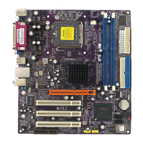
Motherboard Components Introducing the Motherboard... - Page 11 Table of Motherboard Components LABEL COMPONENT 1 CPU Socket LGA775 socket for Pentium 4/Celeron D/Pentium D CPUs 2 CPU_FAN CPU cooling fan connector 3 DIMM1~2 184-pin DDR SDRAM slots 4 IR1 Onboard infrared header 5 FDD1 Floppy disk drive connector 6 ATX1 Standard 20-pin ATX power connector 7 IDE1...
- Page 12 Memo Introducing the Motherboard...
-
Page 13: Installing The Motherboard
Chapter 2 Installing the Motherboard Safety Precautions • Follow these safety precautions when installing the motherboard • Wear a grounding strap attached to a grounded device to avoid damage from static electricity • Discharge static electricity by touching the metal case of a safely grounded object before working on the motherboard •... -
Page 14: Checking Jumper Settings
Do not over-tighten the screws as this can stress the motherboard. Checking Jumper Settings This section explains how to set jumpers for correct configuration of the motherboard. Setting Jumpers Use the motherboard jumpers to set system configuration options. Jumpers with more than one pin are numbered. -
Page 15: Checking Jumper Settings
Checking Jumper Settings The following illustration shows the location of the motherboard jumpers. Pin 1 is labeled. Jumper Settings Type Setting (default) Jumper Description 1-2: NORMAL 2-3: CLEAR CLR_CMOS 3-pin CLEAR CMOS Before clearing the CMOS, Clear_CMOS make sure to turn off the sys- tem. -
Page 16: Connecting Case Components
Connecting Case Components After you have installed the motherboard into a case, you can begin con- necting the motherboard components. Refer to the following: Connect the CPU cooling fan cable to CPU_FAN. Connect the case cooling fan connector to SYS_FAN. Connect the case speaker cable to SPK1. -
Page 17: Front Panel Header
SPK1: Internal speaker Signal Name Signal Ground ATX1: ATX 20-pin Power Connector Signal Name Signal Name +3.3V +3.3V +3.3V -12V Ground Ground PS ON# Ground Ground Ground Ground Ground PWRGD +5VSB +12V ATX12V: ATX12V Power Connector Signal Name Ground Ground +12V +12V Front Panel Header... -
Page 18: Installing Hardware
Power/Sleep/Message waiting LED Connecting pins 2 and 4 to a single or dual-color, front panel mounted LED provides power on/off, sleep, and message waiting indication. Reset Switch Supporting the reset function requires connecting pin 5 and 7 to a momentary-contact switch that is normally open. -
Page 19: Cpu Installation Procedure
CPU Installation Procedure The following illustration shows CPU installation components. Read and follow the instructions shown on the sticker on the CPU cap. B. Unload the cap · Use thumb & forefinger to hold the lifting tab of the cap. ·... -
Page 20: Installing Memory Modules
Installing Memory Modules This motherboard accommodates two 184-pin unbuffered Double Data Rate (DDR) SDRAM (Synchronous Dynamic Random Access Memory) memory modules, and supports up to DDR 400/333/266. Each module can be installed with 1 GB of memory, the total maximum memory size is 2 GB. - Page 21 Table A: DDR (memory module) QVL (Qualified Vendor List) The following DDR400 memory modules have been tested and qualified for use with this motherboard. Size Vendor Module Name Infineon HYS64D16301GU-5-B 128 MB NANYA NT128D64SH4B1G-5 NANYA NT128D64SH4B1G-5T Infineon HYS64D32300GU-5-B Infineon HYS64D32300HU-5-C Micron MT8VDDT3264AG-40BC4 256 MB...
-
Page 22: Installing A Hard Disk Drive/Cd-Rom/Sata Hard Drive
Installing a Hard Disk Drive/CD-ROM This section describes how to install IDE devices such as a hard disk drive and a CD-ROM drive. About IDE Devices Your motherboard has a primary and secondary IDE channel interface (IDE1 and IDE2). An IDE ribbon cable supporting two IDE devices is bundled with the motherboard. You must orient the cable connector so that the pin1 (color) edge of the cable corresponds to the pin 1 of the I/O port connector. - Page 23 About SATA Connectors Your motherboard features two SATA connectors supporting a total of two drives. SATA , or Serial ATA (Advanced Technology Attachment) is the standard interface for the IDE hard drives which are currently used in most PCs. These connectors are well designed and will only fit in one orientation.
-
Page 24: Installing A Floppy Diskette Drive
Installing a Floppy Diskette Drive The motherboard has a floppy diskette drive (FDD1) interface and ships with a diskette drive ribbon cable that supports one or two floppy diskette drives. You can install a 5.25- inch drive and a 3.5-inch drive with various capacities. The floppy diskette drive cable has one type of connector for a 5.25-inch drive and another type of connector for a 3.5-inch drive. -
Page 25: Installing Add-On Cards
Installing Add-on Cards The slots on this motherboard are designed to hold expansion cards and connect them to the system bus. Expansion slots are a means of adding or enhancing the motherboard’s features and capabilities. With these efficient facilities, you can increase the motherboard’s capabili- ties by adding hardware that performs tasks that are not part of the basic system. - Page 26 Follow these instructions to install an add-on card: Remove a blanking plate from the system case corresponding to the slot you are going to use. Install the edge connector of the add-on card into the expansion slot. Ensure that the edge connector is correctly seated in the slot. Secure the metal bracket of the card to the system case with a screw.
-
Page 27: Connecting Optional Devices
Connecting Optional Devices Refer to the following for information on connecting the motherboard’s optional devices: SPDIFO1: SPDIF out header This is an optional header that provides an S/PDIF (Sony/Philips Digital Interface) output to digital multimedia device through optical fiber or coaxial connector. Signal Name Function SPDIF digital output... - Page 28 USB3~4: Front Panel USB headers The motherboard has four USB ports installed on the rear edge I/O port array. Additionally, some computer cases have USB ports at the front of the case. If you have this kind of case, use auxiliary USB connector to connect the front-mounted ports to the motherboard. Signal Name Function USBPWR...
- Page 29 CD_IN: Analog Audio Input header Signal Name Function CD In left channel CD in_L Ground Ground CD In right channel CD in_R AUX_IN: Auxliary In header Signal Name Function AUX In left channel AUX_L Ground Ground AUX In right channel AUX_R Installing the Motherboard...
-
Page 30: Connecting I/O Devices
Connecting I/O Devices The backplane of the motherboard has the following I/O ports: Use the upper PS/2 port to connect a PS/2 pointing device. PS2 Mouse Use the lower PS/2 port to connect a PS/2 keyboard. PS2 Keyboard Parallel Port (LPT1) Use LPT1 to connect printers or other parallel communications devices. -
Page 31: Using Bios
Chapter 3 Using BIOS About the Setup Utility The computer uses the latest Award BIOS with support for Windows Plug and Play. The CMOS chip on the motherboard contains the ROM setup instructions for configuring the motherboard BIOS. The BIOS (Basic Input and Output System) Setup Utility displays the system’s configura- tion status and provides you with options to set system parameters. -
Page 32: Bios Navigation Keys
Press DEL to enter SETUP Pressing the delete key accesses the BIOS Setup Utility: Phoenix-AwardBIOS CMOS Setup Utility: Standard CMOS Features Frequency Control Advanced BIOS Features Load Fail-Safe Defaults Advanced Chipset Features Load Optimized Defaults Integrated Peripherals Set Supervisor Password Power Management Setup Set User Password PnP/PCI Configurations... -
Page 33: Updating The Bios
Updating the BIOS You can download and install updated BIOS for this motherboard from the manufacturer’s Web site. New BIOS provides support for new peripherals, improvements in performance, or fixes for known bugs. Install new BIOS as follows: If your motherboard has a BIOS protection jumper, change the setting to allow BIOS flashing. -
Page 34: Standard Cmos Features
Standard CMOS Features This option displays basic information about your system. Phoenix-AwardBIOS CMOS Setup Utility Standard CMOS Features Date (mm:dd:yy) Mon, Mar 1 1999 Time (hh:mm:ss) 11 : 11 : 20 Item Help IDE Channel 0 Master IDE Channel 0 Slave IDE Channel 1 Master Menu Level IDE Channel 1 Slave... - Page 35 If you are setting up a new hard disk drive that supports LBA mode, more than one line will appear in the parameter box. Choose the line that lists LBA for an LBA drive. IDE Channel 0/1 Master/Slave (Auto) Leave this item at Auto to enable the system to automatically detect and configure IDE devices on the channel.
-
Page 36: Advanced Bios Features
Advanced BIOS Features This option defines advanced information about your system. Phoenix-AwardBIOS CMOS Setup Utility Advanced BIOS Features CPU Feature [Press Enter] Item Help Hard Disk Boot Priority [Press Enter] CPU L3 Cache [Enabled] Hyper-Threading Technology [Enabled] Menu Level Quick Power On Self Test [Enabled] First Boot Device [Floppy]... - Page 37 TM2 Bus Ratio (0 X) This item helps you to set the frequency (bus ratio) of the throttled performance that will be initiated when the on-die sensor goes from not hot to hot. You may set the bus ratio number from 0-255. This feature is available when CPU supports Thermal Monitor 2. TM2 Bus VID (0.8375V) This item helps you to set the voltage of the throttled performance that will be initiated when the on-die sensor goes from not hot to hot.
- Page 38 Hard Disk Boot Priority (Press Enter) Scroll to this item and press <Enter> to view the following screen: Phoenix-AwardBIOS CMOS Setup Utility Hard Disk Boot Priority 1. Pri. Master: Item Help 2. Pri. Slave: 3. Sec. Master: 4. Sec. Slave: Menu Level 5.
- Page 39 Typematic Rate Setting (Disabled) If this item is enabled, you can use the following two items to set the typematic rate and the typematic delay settings for your keyboard. • Typematic Rate (Chars/Sec): Use this item to define how many charac- ters per second are generated by a held-down key.
-
Page 40: Advanced Chipset Features
Advanced Chipset Features These items define critical timing parameters of the motherboard. You should leave the items on this page at their default values unless you are very familiar with the technical specifications of your system hardware. If you change the values incorrectly, you may introduce fatal errors or recurring instability into your system. - Page 41 System BIOS Cacheable (Disabled) When this item is enabled, the System BIOS will be cached for faster execution. Video BIOS Cacheable (Disabled) When this is enabled, the Video RAM will be cached resulting to better performance. However, if any program was written to this memory area, this may result to system error. AGP Aperture Size (MB) (128) This item defines the size of the aperture if you use an AGP graphics adapter.
-
Page 42: Integrated Peripherals
Integrated Peripherals These options display items that define the operation of peripheral components on the system’s input/output ports. Phoenix-AwardBIOS CMOS Setup Utility Integrated Peripherals Item Help OnChip IDE Device [Press Enter] Onboard Device [Press Enter] SuperIO Device [Press Enter] Menu Level : Move Enter: Select +/-/PU/PD:Value F10:Save ESC:Exit F1: General Help... - Page 43 IDE Primary/Secondary Master/Slave PIO (Auto) Each IDE channel supports a master device and a slave device. These four items let you assign the kind of PIO (Programmed Input/Output) was used by the IDE devices. Choose Auto to let the system auto detect which PIO mode is best, or select a PIO mode from 0-4. IDE Primary/Secondary Master/Slave UDMA (Auto) Each IDE channel supports a master device and a slave device.
-
Page 44: Superio Device
USB Keyboard Support (Enabled) This item allows the BIOS to interact with a USB keyboard or mouse to work with MS-DOS based utilities and non-Windows modes. USB Mouse Support (Enabled) Enable this item if you plan to use a mouse connected through the USB port in a legacy operating system (such as DOS) that does not support Plug and Play. - Page 45 KB Power ON Password (Enter) When the POWER ON Function is set to Password, use this item to set the passowrd. Hot Key Power On (Ctrl-F12) When the POWER ON Function is set to Hot Key, use this item to set the hot key combination that turns on the system.
- Page 46 SPP allows data output only. Extended Capabilities Port (ECP) and Enhanced Parallel Port (EPP) are bi-directional modes, allowing both data input and output. ECP and EPP modes are only supported with EPP- and ECP-aware peripherals. ECP Mode Use DMA (3) When the onboard parallel port is set tp ECP mode, the parallel port can use DMA3 or DMA1.
-
Page 47: Power Management Setup
Power Management Setup This option lets you control system power management. The system has various power- saving modes including powering down the hard disk, turning off the video, suspending to RAM, and software power down that allows the system to be automatically resumed by certain events. - Page 48 Suspend Type (Stop Grant) If this item is set to the default Stop Grant, the CPU will go into Idle Mode during power saving mode. MODEM Use IRQ (3) If you want an incoming call on a modem to automatically resume the system from a power-saving mode, use this item to specify the interrupt request line (IRQ) that is used by the modem.
-
Page 49: Pnp/Pci Configurations
FDD, COM, LPT Port (Disabled) When this item is enabled, the system power will resume the system from a power saving mode if there is any activity on FDD, COM, or LPT port. PCI PIRQ [A-D] # (Disabled) When this item is enabled, the system power will resume the system from a power saving mode if there is any activity on PCI or PIRQ devices. -
Page 50: Pc Health Status
PCI/VGA Palette Snoop (Disabled) This item is designed to overcome problems that can be caused by some non-standard VGA cards. This board includes a built-in VGA system that does not require palette snooping so you must leave this item disabled. Assign IRQ For USB (Enabled) “Enable”... -
Page 51: Frequency Control
Target Temperature (Disabled) This item enables throttling when CPU targets the temperature. Shutdown Temperature (Disabled) Enables you to set the maximum temperature the system can reach before powering down. System Component Characteristics These items allow end users and technicians to monitor data provided by the BIOS on this motherboard. -
Page 52: Load Fail-Safe Settings
Load Fail-Safe Defaults This option opens a dialog box that lets you install fail-safe defaults for all appropriate items in the Setup Utility: Press <Y> and then <Enter> to install the defaults. Press <N> and then <Enter> to not install the defaults. The fail-safe defaults place no great demands on the system and are generally stable. -
Page 53: Save & Exit Setup
Save & Exit Setup Highlight this item and press <Enter> to save the changes that you have made in the Setup Utility and exit the Setup Utility. When the Save and Exit dialog box appears, press <Y> to save and exit, or press <N> to return to the main menu: Exit Without Saving Highlight this item and press <Enter>... - Page 54 Memo Using BIOS...
-
Page 55: Using The Motherboard Software
Chapter 4 Using the Motherboard Software About the Software CD-ROM The support software CD-ROM that is included in the motherboard package contains all the drivers and utility programs needed to properly run the bundled products. Below you can find a brief description of each software program, and the location for your motherboard version. -
Page 56: Running Setup
Setup Tab Setup Click the Setup button to run the software installation program. Select from the menu which software you want to install. Browse CD The Browse CD button is the standard Windows command that allows you to open Windows Explorer and show the contents of the support Before installing the software from Windows Explorer, look for a file named README.TXT, INSTALL.TXT or something similar. - Page 57 Click Next. The following screen appears: Check the box next to the items you want to install. The default options are recommended. Click Next run the Installation Wizard. An item installation screen appears: Follow the instructions on the screen to install the items. Drivers and software are automatically installed in sequence.
-
Page 58: Manual Installation
Manual Installation Insert the CD in the CD-ROM drive and locate the PATH.DOC file in the root directory. This file contains the information needed to locate the drivers for your motherboard. Look for the chipset and motherboard model; then browse to the directory and path to begin installing the drivers. -
Page 59: Multi-Language Translation
Caractéristiques Processeur Cette carte mère utilise un type LGA775 de Pentium 4/Celeron D/Pentium D présentant les fonctionnalités suivantes : • Peut recevoir les derniers processeurs Intel Pentium 4/Celeron D/Pentium D • Prend en charge un bus système (FSB) de 800/533/400 MHz •... - Page 60 CODEC Audio • Conforme au CODEC AC’97 V2.3 • Prend en charge le CODEC audio 6 canaux destiné aux systèmes multimédia • Offre trois entrées stéréo de niveau de ligne analogique avec contrôle de volume 5 bits: Ligne d’entrée, CD, AUX •...
- Page 61 Feature Prozessor Das Motherboard verwendet einen LGA775 Typ Pentium 4/Celeron D/Pentium D mit den folgenden Eigenschaften: • Nimmt die neuesten Pentium 4/Celeron D/Pentium D Prozessoren auf • Unterstützt einen Systembus (FSB) mit 800/533/400 MHz • Unterstützt eine CPU mit „Hyper-Threading“ Technologie Bei der „Hyper-Threading”...
- Page 62 Audio CODEC • Entspricht AC' 97 V2.3 CODEC • Unterstützt 6-Kanal Audio CODEC, entwickelt für Multimedia PC-Systeme • Stellt drei analoge Line-Level Stereoeingänge mit 5-bit Lautstärkeregelung zur Verfügung: Line-in, CD, AUX • Entspricht den Anforderungen von Microsoft WHL/WLP 2.0 Erweiterungsoptionen Das Motherboard bietet die folgenden Erweiterungsoptionen: •...
- Page 63 Caratteristiche Processore La scheda madre utilizza un tipo LGA775 di Pentium 4/Celeron D/Pentium D che offre le seguenti caratteristiche: • Compatibilità con i più recenti processori Intel Pentium 4/Celeron D/ Pentium D • Supporto di un bus di sistema (FSB) da 800/533/400 MHz •...
- Page 64 CODEC Audio • Conforme alla specifica AC’97 v2.3 CODEC • Supporto di CODEC audio a 6 canali per sistemi PC multimediali • Tre ingressi analogici stereo lineari con controllo volume a 5 bit: Line-In, CD, AUX • Compatibile con i requisiti per audio WHL/WLP 2. di Microsoft Opzioni di espansione La scheda madre è...
- Page 65 Característica Procesador Esta placa principal usa un tipo LGA775 de Pentium 4/Celeron D/Pentium D que lleva las sigtes. características: • Acomoda los últimos procesadores Intel Pentium 4/Celeron D/Pentium D • Soporta un bus de sistema (FSB) de 800/533/400 MHz • Soporta la CPU con tecnología "Hyper-Threading"...
- Page 66 CODEC de audio • Conforme con el CODEC AC’97 v2.3 • Soporta CODEC de audio de 6 canales diseñaods para los sistemas multimedia • Provee tres entradas en estéreo a nivel de línea análogicas con control de volumen de 5-bit: LIne-in, CD, AUX •...
- Page 67 Características Processador Esta motherboard usa um tipo de Pentium 4/Celeron D/Pentium D LGA775 que possui as seguintes características: • Acomoda os processadores Intel Pentium 4/Celeron D/Pentium D mais recentes • Suporta um bus de sistema (FSB) de 800/533/400 MHz • Suporta CPU de tecnologia “Hyper Threading”...
- Page 68 Codec Áudio • Cumpre com o AC’97 v2.3 CODEC • Suporta CODEC áudio com 6 canais concebido para sistemas multimédia para • Fornece três entradas estéreo nível de linha analógicas com controlo de volume de 5 bits: LIne-in, CD, AUX Cumpre com os requisitos áudio WHL/WLP 2.0 da Microsoft •...
- Page 69 機能 プロセッサ このマザーボードには LGA775 タイプのPentium 4/Celeron D/Pentium D を取り付 け可能で、次の特徴があります: • Intel Pentium 4/Celeron D/Pentium D プロセッサに対応 • 800/533/400 MHzのシステムバス(FSB)をサポート • “ハイパースレッド” 技術をサポート ハイパースレッド(HT) 技術というのは、オペレーションシステムに2つのプロセッサが存 在すると認識させることで、実際には2つのスレッドを1つのプロセッサで同時に執行させ 、平行利用を可能とする技術です。 チップセット Intel 865G Northbridge (NB)と82801EB Southbridge (SB)チップセットは、実証さ れた信頼性と性能を持つ革新的で拡張性のあるアーキテクチャに基づいています。 865G (NB) • データ転送率が800/533/400MHzのPentium 4/Celeron D/Pentium D プロセッサに対応...
- Page 70 Audio CODEC • AC’97 v2.3仕様に適合。 • PCマルチメディアシステムの6チャネルオーディオCODECをサポート。 • 5ビット音声コントロール可能のアナログラインレベルのステレオ入力が3つ:ライ ンイン、CD、およびAUX。 • Microsoft WHL/WLP 2.0 オーディオ基準に準拠 拡張オプション 本マザーボードでは、次の拡張機能が利用できます。 • 32ビットPCIスロット x3 • AGP スロットx1 • 7ピンSATAコネクタ X2 • IDEヘッダー (4つのIDEデバイスの接続を可能) • フロッピーディスクドライブインターフェイス x1 • オプションのCNRスロットx1 このマザーボードは、100/66/33MB/秒の転送速度でのUltra DMAバスマスタリングを サポートします。 オンボードLAN (オプション) 当マザーボードは次のLAN構成のいずれかに対応しております: •...
- Page 71 특성 프로세서 본 마더보드는 팬티엄 4/샐러론 D/팬티엄 D 의 LGA775 을 사용하며 다음과 같은 특 성을 지닙니다: • 최신 인텔 팬티엄 4/샐러론 D/팬티엄 D 프로세서 사용 • 800/533/400 MHz 의 시스템 버스 (FSB) 지원 • "Hyper-Threading" 기술의 CPU 지원 “Hyper-Threading" 기술은 운영 체제가 두개의 프로세서에 연결되어 있는 것처럼, 두...
- Page 72 오디오 코덱 • AC’ 97 v2.3 코덱 부합 • PC 멀티미디어 시스템을 위해 디자인 된 6 채널 오디오 코덱 지원 • 5 비트 볼륨 컨트롤의 아날로그 라인 레벨 스테레오 입력 3개 : Line-in, CD, • Microsoft WHL/WLP 2.0 오디오 요구 조건에 부합 확장...
- Page 73 功能 處理器 本主機板適用於LGA775 型Pentium 4 /Celeron D/Pentium D且具有如下功能: ‧ 支援Intel Pentium 4 /Celeron D/Pentium D 處理器; ‧ 支援高達800/533/400 MHz之系統匯流排(FSB); ‧ 支援使用超執行緒(Hyper-Threading)技術之CPU。 利用“超執行緒(HT)"技術,可使作業系統在相當於裝上了兩具處理器的狀態下運作 :利用一個"實體"處理器模擬出兩個獨立的"邏輯"處理器,同時執行兩個工作緒 。 晶片組 Intel 865G北橋(NB)及82801EB(ICH5)南橋(SB)晶片組在研發設計上採用了創新且具擴 充性之架構,具備優良的可靠性及性能。 865G (NB) ‧ 支援傳輸率高達800/533/400MHz的Pentium 4 /Celeron D/Pentium D 處理器; ‧ 支援400/333/266 MHz的DDR-SDRAM; ‧...
- Page 74 音頻編碼器 ‧ 相容於AC'97 2.3版CODEC規格; ‧ 支援為個人電腦多媒體系統設計的6聲道音訊CODEC功能; ‧ 提供具有5位元音量控制功能的3種類比線級立體音效輸入:Lin-in、CD、及 AUX; 符合Microsoft WHL/WLP 2.0 音訊規格。 ‧ 擴充選項 本主機板包括下列擴充選項: • 3 個 32-bit PCI 插槽; • 1 個 AGP 插槽 ; • 2 個 7針SATA插頭 • 2 個 IDE 接頭,支援 4個 IDE 裝置; •...
- Page 75 功能 处理器 此主板使用 LGA775 型 Pentium 4/Celeron D/Pentium D CPU,具备以下特点: • 支持最新的 Intel Pentium 4/Celeron D/Pentium D 处理器 • 支持 800/533/400 MHz 系统总线 (FSB) • 支持“多线程”技术 CPU “多线程”技术可以让操作系统认为自己连接了两个处理器,允许两个线程并行运行 ,每个线程位于同一处理器中的单独“逻辑”处理器中。 芯片组 Intel 865G 北桥 (NB) 和 82801EB(ICH5) 南桥 (SB) 芯片组是基于一种新型的、可扩 展的架构,能提供已经证明的可靠性和高性能。 865G (NB) •...
-
Page 76: Onboard Lan
扩展选项 此主板提供如下扩展选项: • 3 个 32 位 PCI 扩展插槽 • 1 个 AGP 槽 • 2 个 7-pin SATA 接口 • 2 个 IDE 接口,可支持 4 个 IDE 设备 • 1 个 软驱接口 • 1 个 可选 CNR 插槽 主板支持 Ultra DMA 总线控制,传输速率可达 100/66/33MB/s。 Onboard LAN(可选)... - Page 77 Характеристики Процессор Плата построена на базе процессора Pentium 4/Celeron D/Pentium D LGA775 и обладает следующими характеристиками: • Поддерживает новейшие процессоры Intel Pentium 4/Celeron D/Pentium • Поддерживает системные шины (FSB) с частотой 800/533/4000MHz • Поддерживает технологию CPU “Hyper-Threading” Технология “Hyper-Threading” «убеждает» операционную систему в том, что в машине имеется...
- Page 78 Аудио CODEC • Совместимо с AC’97 v2.3 CODEC • Поддерживает 6-канальный аудио CODEC для мультимедиальных компьютерных систем • Обеспечивает три аналоговых стереовхода с 5-битной регуляцией громкости: Line-in, CD, AUX • Соответствует требованиям Microsoft WHL/WLP 2.0 аудио Возможности расширения Существуют следуюшие опции расширения данной материнской платы: •...
- Page 79 Cechy Procesor Ta płyta główna zaopatrzona jest w procesor Pentium 4/Celeron D/Pentium D typu LGA775 i charakteryzuje się następującymi cechami: • Obsługuje najnowsze procesory Intel Pentium 4/Celeron D/Pentium D • Obsługuje szynę systemowa (FSB) 800/533/400MHz • Zabezpiecza technologię CPU “Hyper-Threading” Technologia “Hyper-Threading”...
- Page 80 Audio CODEC • Zgodne z audio CODEC AC’97 w wersji 2.3 • Obsługuje 6 kanałów audio CODEC dla komputerowych systemów multimedialnych • Zapewnia trzy wejściowe, analogowe linie stereo z 5 bitową regulacją głośności: Line-in, CD, AUX • Zgodna ze specyfikacją Microsoft WHL/WLP 2.0 audio Możliwości rozbudowy Płyta głwna wyposażona jest w następujące gniazda: •...
- Page 81 Vlastnosti Procesor Tato základní deska je určena pro procesory Pentium 4/Celeron D/Pentium D LGA775 a může nabídnout následující vlastnosti: • Základní deska je určena pro nejnovější procesy Intel Pentium 4/Celeron D/Pentium D • Podporuje taktování systémové sběrnice (FSB) na frekvenci 800/533/400 •...
- Page 82 Audio kodek • Splňuje požadavky standardu kodeku AC’97 v2.3 • Podpora 6kanálového zvukového kodeku určeného pro multimediální PC systémy • Nabízí tří analogové linkové stereo vstupy s 5bitovým řízení hlasitosti: LINE-IN, CD, AUX • Splňuje požadavky na audio zařízení Microsoft WHL/WLP 2.0 Možnosti rozšíření...
- Page 83 Caracteristici Procesorul Această placă de bază utilizează Pentium 4/Celeron D/Pentium D de tipul LGA775, având următoarele caracteristici: • Este destinată celor mai recente procesoare Intel Pentium 4/Celeron D/ Pentium D • Funcţionează cu bus sistem (FSB) de 800/533/400 MHz • Este compatibilă...
- Page 84 Audio CODEC • Compatibil cu CODEC-ul AC’97, versiunea 2.3 • Suportă CODEC cu şase canale audio destinate sistemelor multimedia ale calculatoarelor • Oferă trei intrări audio analoge stereo, cu un control al volumului sonor de 5 biţi: Intrare audio, CD, AUX •...
- Page 85 Спецификация Процесор Тази дънна платка използва Pentium 4/Celeron D/Pentium D тип LGA775 със следните спецификации: • поддръжка на последни модели процесори Intel Pentium 4/Celeron D/ Pentium D • поддръжка на системна шина със скорост 800/533/400MHz • поддръжка на процесори с технология “Hyper-Threading" Технологията...
- Page 86 Audio CODEC • съвместимост с AC’97 V2.3 CODEC • поддръжка на 6-канален аудио CODEC специално създаден за мултимедийни системи • Включва три аналогови линейни стерео входа с 5-битов контрол на силата на звука: LINE-IN, CD, AUX • съвместимо с спецификацията Microsoft WHL/WLP 2.0 Възможности...
- Page 87 Jellemző Processzor Ez az alaplap LGA775 típusú Pentium 4/Celeron D/Pentium D számára készült, és a következő jellemzőkkel bír: • A legújabb Intel Pentium 4/Celeron D/Pentium D processzorokkal működik • 800/533/400 MHz sebességű rendszerbuszt (FSB) támogat • Támogatja a „Hyper-Threading” technológiát használó központi egységeket A „Hyper-Threading”...
- Page 88 Audio CODEC • Kompatibilis az AC’97 2.3-as CODEC változatával • A számítógép multimédiás rendszereinek szánt hat csatornás audio CODEC-et támogat • Három analóg sztereo bemenetet biztosít 5 bites hangerő vezérléssel: bemenet, CD, AUX • Megfelel a Microsoft WHL/WLP 2.0 audio követelményeinek Bővítési lehetőségek Az alaplap a következő...
Need help?
Do you have a question about the 865G-M8 and is the answer not in the manual?
Questions and answers