Table of Contents
Advertisement
Quick Links
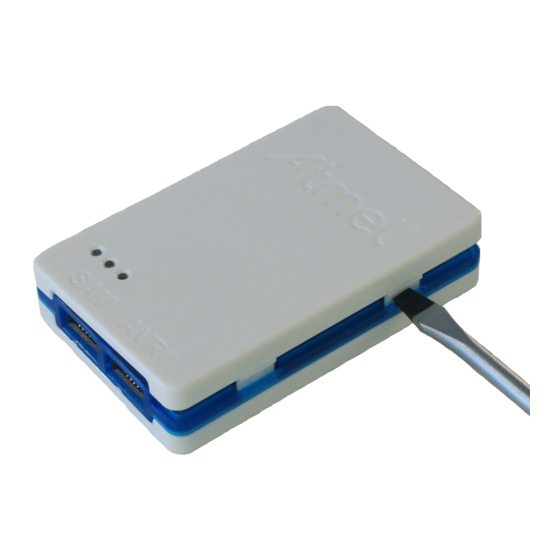
The Atmel-ICE Debugger
Atmel-ICE is a powerful development tool for debugging and programming Arm
®
and AVR
microcontrollers with On-Chip Debug capability.
It supports:
•
Programming and on-chip debugging of all Microchip AVR 32-bit microcontrollers on both JTAG and aWire
interfaces
•
Programming and on-chip debugging of all Microchip AVR XMEGA
wire interfaces
•
Programming (JTAG, SPI, UPDI) and debugging of all Microchip AVR 8-bit microcontrollers with OCD support
on either JTAG, debugWIRE or UPDI interfaces
•
Programming and debugging of all Microchip SAM Arm Cortex-M based microcontrollers on both SWD and
JTAG interfaces
•
Programming (TPI) of all Microchip tinyAVR
©
2020 Microchip Technology Inc.
Programmers and Debuggers
Atmel-ICE
®
8-bit microcontrollers with support for this interface
User Guide
®
®
Cortex
-M based Microchip SAM
®
family devices on both JTAG and PDI two-
DS50002999A-page 1
Advertisement
Table of Contents

Related Manuals for Microchip Technology Atmel-ICE


Summary of Contents for Microchip Technology Atmel-ICE
-
Page 1: The Atmel-Ice Debugger
Programmers and Debuggers Atmel-ICE The Atmel-ICE Debugger ® ® Atmel-ICE is a powerful development tool for debugging and programming Arm Cortex -M based Microchip SAM ® and AVR microcontrollers with On-Chip Debug capability. It supports: • Programming and on-chip debugging of all Microchip AVR 32-bit microcontrollers on both JTAG and aWire interfaces ®... -
Page 2: Table Of Contents
The Atmel-ICE Debugger..........................1 Introduction............................. 4 1.1. Introduction to the Atmel-ICE....................... 4 1.2. Atmel-ICE Features........................4 1.3. System Requirements........................4 Getting Started with the Atmel-ICE......................5 2.1. Full Kit Contents........................... 5 2.2. Basic Kit Contents........................5 2.3. PCBA Kit Contents........................6 2.4. - Page 3 UC3 Targets........................49 7.2. debugWIRE Targets........................49 Release History and Known issues.......................50 8.1. Firmware Release History......................50 8.2. Known Issues Concerning the Atmel-ICE.................. 50 Product Compliance..........................51 9.1. RoHS and WEEE........................51 9.2. CE and FCC..........................51 10. Revision History............................ 52 The Microchip Website..........................53...
-
Page 4: Introduction
10-pin 100-mil, and 20-pin 100-mil headers. Several kit options are available with different cabling and adapters. System Requirements The Atmel-ICE unit requires that a front-end debugging environment MPLAB X IDE, or Atmel Studio is installed on your computer. The Atmel-ICE should be connected to the host computer using the USB cable provided, or a certified Micro-USB cable. -
Page 5: Getting Started With The Atmel-Ice
Programmers and Debuggers Getting Started with the Atmel-ICE Getting Started with the Atmel-ICE Full Kit Contents The Atmel-ICE full kit contains these items: • Atmel-ICE unit • USB cable (1.8m, high-speed, Micro-B) • Adapter board containing 50-mil AVR, 100-mil AVR/SAM, and 100-mil 20-pin SAM adapters •... -
Page 6: Pcba Kit Contents
Programmers and Debuggers Getting Started with the Atmel-ICE Figure 2-2. Atmel-ICE Basic Kit Contents PCBA Kit Contents The Atmel-ICE PCBA kit contains these items: • Atmel-ICE unit without plastic encapsulation Figure 2-3. Atmel-ICE PCBA Kit Contents Spare Parts Kits The following spare parts kits are available: •... -
Page 7: Kit Overview
Programmers and Debuggers Getting Started with the Atmel-ICE Figure 2-4. Atmel-ICE Adapter Kit Contents Figure 2-5. Atmel-ICE Cable Kit Contents Kit Overview The Atmel-ICE kit options are shown diagrammatically here: Figure 2-6. Atmel-ICE Kit Overview Full kit Basic kit PCBA kit Adapter kit... -
Page 8: Assembling The Atmel-Ice
To assemble your Atmel-ICE into its default configuration, connect the 10-pin 50-mil IDC cable to the unit, as shown below. Be sure to orient the cable so that the red wire (pin 1) on the cable aligns with the triangular indicator on the blue belt of the enclosure. -
Page 9: Opening The Atmel-Ice
Opening the Atmel-ICE Note: For normal operation, the Atmel-ICE unit must not be opened. Opening the unit is done at your own risk. Anti-static precautions should be taken. The Atmel-ICE enclosure consists of three separate plastic components - top cover, bottom cover, and blue belt - which are snapped together during assembly. - Page 10 Programmers and Debuggers Getting Started with the Atmel-ICE blue belt, apply some inward pressure, and twist gently. Repeat the process on the other snapper holes, and the top cover will pop off. Figure 2-12. Opening the Atmel-ICE (1) Figure 2-13. Opening the Atmel-ICE (2)
-
Page 11: Powering The Atmel-Ice
Powering the Atmel-ICE The Atmel-ICE is powered by the USB bus voltage. It requires less than 100 mA to operate, and can, therefore, be powered through a USB hub. The power LED will illuminate when the unit is plugged in. When not connected in an active programming or debugging session, the unit will enter low-power consumption mode to preserve your computer's battery. -
Page 12: Connecting The Atmel-Ice
MCU type - for example, a SAM device mounted in an AVR STK600 stack should use the AVR header. Various cabling and adapters are available in the different Atmel-ICE kits. An overview of connection options is shown. -
Page 13: Connecting To A Jtag Target
Use the 50-mil 10-pin flat cable (included in some kits) to connect directly to a board supporting this header type. Use the AVR connector port on the Atmel-ICE for headers with the AVR pinout, and the SAM connector port for headers complying with the Arm Cortex Debug header pinout. -
Page 14: Connecting To An Awire Target
Use the adapter board (included in some kits) to connect to a standard 50-mil aWire header. Connection to a Custom 100-mil Header The 10-pin mini-squid cable should be used to connect between the Atmel-ICE AVR connector port and the target board. Three connections are required, as described in the table below. -
Page 15: Connecting To A Updi Target
Use the adapter board (included in some kits) to connect to a standard 50-mil UPDI header. Connection to a Custom 100-mil Header The 10-pin mini-squid cable should be used to connect between the Atmel-ICE AVR connector port and the target board. Three connections are required, as described in the table below. -
Page 16: Connecting To An Spi Target
Use the adapter board (included in some kits) to connect to a standard 50-mil SPI header. Connection to a custom 100-mil Header The 10-pin mini-squid cable should be used to connect between the Atmel-ICE AVR connector port and the target board. Three connections are required, as described in Table 3-5. -
Page 17: Connecting To A Tpi Target
Use the adapter board (included in some kits) to connect to a standard 50-mil SPI header. Connection to a Custom 100-mil Header The 10-pin mini-squid cable should be used to connect between the Atmel-ICE AVR connector port and the target board. Six connections are required, as described in the table below. -
Page 18: Connecting To An Swd Target
JTAG connectors are, however, not pin-compatible, so this depends upon the layout of the target board in use. When using an STK600 or a board making use of the AVR JTAG pinout, the AVR connector port on the Atmel-ICE must be used. -
Page 19: Connecting To Data Gateway Interface
3.10 Connecting to Data Gateway Interface The Atmel-ICE supports a limited Data Gateway Interface (DGI) when debugging and programming is not in use. Functionality is identical to that found on Microchip Xplained Pro kits powered by the Microchip EDBG device. -
Page 20: On-Chip Debugging
Run Mode When in Run mode, the execution of code is completely independent of the Atmel-ICE. The Atmel-ICE will continuously monitor the target device to see if a break condition has occurred. When this happens, the OCD system will interrogate the device through its debug interface, allowing the user to view the internal state of the device. - Page 21 Reset (optional). Used to reset the target device. Connecting this pin is recommended since it allows the Atmel-ICE to hold the target device in a Reset state, which can be essential to debugging in certain scenarios. Target voltage reference. Atmel-ICE samples the target voltage on this pin to power the level converters correctly.
- Page 22 TMS and TCK are connected in parallel; TDI and TDO are connected in a serial chain. • nSRST on the Atmel-ICE probe must be connected to RESET on the devices if any of the devices in the chain disables its JTAG port •...
- Page 23 Use the 50-mil 10-pin flat cable (included in some kits) to connect directly to a board supporting this header type. Use the AVR connector port on the Atmel-ICE for headers with the AVR pinout, and the SAM connector port for headers complying with the Arm Cortex Debug header pinout.
- Page 24 JTAG connectors are, however, not pin-compatible, so this depends upon the layout of the target board in use. When using an STK600 or a board making use of the AVR JTAG pinout, the AVR connector port on the Atmel-ICE must be used.
-
Page 25: Avr ® Uc3 Devices With Jtag/Awire
Arm core. The ERASE pin is NOT part of any debug header, and the Atmel-ICE is thus unable to assert this signal to unlock a device. In such cases the user should perform the erase manually before starting a debug session. - Page 26 Reset (optional). Used to reset the target device. Connecting this pin is recommended since it allows the Atmel-ICE to hold the target device in a Reset state, which can be essential to debugging in certain scenarios. Target voltage reference. The Atmel-ICE samples the target voltage on this pin to power the level converters correctly.
- Page 27 TMS and TCK are connected in parallel; TDI and TDO are connected in a serial chain. • nSRST on the Atmel-ICE probe must be connected to RESET on the devices if any of the devices in the chain disables its JTAG port •...
- Page 28 Use the 50-mil 10-pin flat cable (included in some kits) to connect directly to a board supporting this header type. Use the AVR connector port on the Atmel-ICE for headers with the AVR pinout, and the SAM connector port for headers complying with the Arm Cortex Debug header pinout.
- Page 29 The aWire interface makes use of the RESET wire of the AVR device to allow programming and debugging functions. A special enable sequence is transmitted by the Atmel-ICE, which disables the default RESET functionality of the pin. When designing an application PCB, which includes a Microchip AVR with the aWire interface, it is recommended to...
-
Page 30: Tinyavr , Megaavr , And Xmega Devices
4.3.7 EVTI/EVTO Usage The EVTI and EVTO pins are not accessible on the Atmel-ICE. However, they can still be used in conjunction with other external equipment. EVTI can be used for the following purposes: •... - Page 31 Use the 50-mil 10-pin flat cable (included in some kits) to connect directly to a board supporting this header type. Use the AVR connector port on the Atmel-ICE for headers with the AVR pinout, and the SAM connector port for headers complying with the Arm Cortex Debug header pinout.
- Page 32 Reset (optional). Used to reset the target device. Connecting this pin is recommended since it allows the Atmel-ICE to hold the target device in a Reset state, which can be essential to debugging in certain scenarios. Target voltage reference. The Atmel-ICE samples the target voltage on this pin to power the level converters correctly.
- Page 33 When designing an application PCB, which includes a Microchip AVR with the PDI interface, the pinout shown in the figure below, should be used. One of the 6-pin adapters provided with the Atmel-ICE kit can then be used to connect the Atmel-ICE probe to the application PCB.
- Page 34 When designing an application PCB, which includes a Microchip AVR with the UPDI interface, the pinout shown below should be used. One of the 6-pin adapters provided with the Atmel-ICE kit can then be used to connect the Atmel-ICE probe to the application PCB.
- Page 35 Important: The Atmel-ICE does not support 12 V on the UPDI line. In other words, if the UPDI pin has been configured as GPIO or RESET, the Atmel-ICE will not be able to enable the UPDI interface.
- Page 36 Programmers and Debuggers On-Chip Debugging The 10-pin mini-squid cable should be used to connect between the Atmel-ICE AVR connector port and the target board. Three connections are required, as described in the table below. Table 4-14. Atmel-ICE UPDI Pin Mapping Atmel-ICE AVR PORT Pin...
- Page 37 Programmers and Debuggers On-Chip Debugging ...continued Atmel-ICE AVR PORT Pins Target Pins Mini-Squid Pin TPI Pinout Pin 5 (TMS) Pin 6 (nSRST) /RESET Pin 7 (not connected) Pin 8 (nTRST) Pin 9 (TDI) Pin 10 (GND) ® 4.4.11 Advanced Debugging (AVR...
- Page 38 If such code is already executing on the Microchip AVR device when starting a debug session, the Atmel-ICE will assert the RESET line while connecting. If this line is wired correctly, it will force the target AVR device into Reset, thereby allowing a JTAG connection.
- Page 39 If such code is already executing on the Microchip AVR device when starting a debug session, the Atmel-ICE will assert the RESET line while connecting. If this line is wired correctly, it will force the target AVR device into Reset, thereby allowing a JTAG connection.
- Page 40 Be sure to check the “use external reset” checkbox in both the programming dialog and debug options dialog in Atmel Studio to allow the Atmel-ICE to assert the RESET line and re-enable the JTAG interface on devices which are running code which disables the JTAG interface by setting the JTAG disable bit.
- Page 41 Let the software front-end take care of things (recommended) • Set and clear DWEN manually (exercise caution, advanced users only!) Important: When manipulating DWEN manually, the SPIEN fuse must remain set to avoid having to use High-Voltage programming. User Guide DS50002999A-page 41 © 2020 Microchip Technology Inc.
- Page 42 If the UPDI pin is to be used as a RESET pin, any stabilizing capacitor must be disconnected when using UPDI, since it will interfere with correct operation of the interface User Guide DS50002999A-page 42 © 2020 Microchip Technology Inc.
- Page 43 If the UPDI pin is used as RESET or GPIO pin, all external drivers on the line must be disconnected during programming or debugging since they may interfere with the correct operation of the interface User Guide DS50002999A-page 43 © 2020 Microchip Technology Inc.
-
Page 44: Hardware Description
The rear panel of the Atmel-ICE houses the Micro-B USB connector. Bottom Panel The bottom panel of the Atmel-ICE has a sticker which shows the serial number and date of manufacture. When seeking technical support, include these details. User Guide DS50002999A-page 44 ©... -
Page 45: Architecture Description
Atmel-ICE Main Board Power is supplied to the Atmel-ICE from the USB bus, regulated to 3.3V by a step-down switch-mode regulator. The VTG pin is used as a reference input only, and a separate power supply feeds the variable-voltage side of the on- board level converters. - Page 46 Zener overvoltage protection diodes, series termination resistors, inductive filters, and ESD protection diodes. All signal channels can be operated in the range 1.62V to 5.5V, although the Atmel-ICE hardware can not drive out a higher voltage than 5.0V. The maximum operating frequency varies according to the target interface in use.
-
Page 47: Software Integration
When debugging a Microchip AVR device, there are some important configuration options. These are found in the Atmel-ICE section in the 'Project Properties' in MPLAB X IDE, or the 'Tool' tab in the project properties view in Atmel Studio. The options which need further explanation are detailed here. -
Page 48: Command-Line Utility
Debug sessions on UC3 target devices over the aWire interface will be automatically tuned to the optimal baud rate by the Atmel-ICE itself. However, if you are experiencing reliability problems related to a noisy debug environment, some tools offer the possibility to force the aWire speed below a configurable limit. -
Page 49: Advanced Debugging Techniques
® UC3 Targets 7.1.1 EVTI/EVTO Usage The EVTI and EVTO pins are not accessible on the Atmel-ICE. However, they can still be used in conjunction with other external equipment. EVTI can be used for the following purposes: • The target can be forced to stop execution in response to an external event. If the Event In Control (EIC) bits in the DC register are written to 0b01, a high-to-low transition on the EVTI pin will generate a breakpoint condition. -
Page 50: Release History And Known Issues
• The initial Atmel-ICE batches had a weak USB connector. A new revision has been made with a new and more robust USB connector. As an interim solution, epoxy glue has been applied to the already produced units of the first version to improve the mechanical stability. -
Page 51: Product Compliance
Product Compliance Product Compliance RoHS and WEEE The Atmel-ICE and all accessories are manufactured per both the RoHS Directive (2002/95/EC) and the WEEE Directive (2002/96/EC). CE and FCC The Atmel-ICE unit has been tested per the essential requirements and other relevant provisions of Directives: •... -
Page 52: Revision History
42330B 03/2016 • Revised On-Chip Debugging chapter • New formatting of firmware release history in Release History and Known issues chapter • Added debug cable pinout 42330A 06/2014 Initial document release User Guide DS50002999A-page 52 © 2020 Microchip Technology Inc. -
Page 53: The Microchip Website
Information contained in this publication regarding device applications and the like is provided only for your convenience and may be superseded by updates. It is your responsibility to ensure that your application meets with User Guide DS50002999A-page 53 © 2020 Microchip Technology Inc. -
Page 54: Trademarks
The Adaptec logo, Frequency on Demand, Silicon Storage Technology, and Symmcom are registered trademarks of Microchip Technology Inc. in other countries. GestIC is a registered trademark of Microchip Technology Germany II GmbH & Co. KG, a subsidiary of Microchip Technology Inc., in other countries. -
Page 55: Worldwide Sales And Service
New York, NY Tel: 46-31-704-60-40 Tel: 631-435-6000 Sweden - Stockholm San Jose, CA Tel: 46-8-5090-4654 Tel: 408-735-9110 UK - Wokingham Tel: 408-436-4270 Tel: 44-118-921-5800 Canada - Toronto Fax: 44-118-921-5820 Tel: 905-695-1980 Fax: 905-695-2078 User Guide DS50002999A-page 55 © 2020 Microchip Technology Inc.
Need help?
Do you have a question about the Atmel-ICE and is the answer not in the manual?
Questions and answers