Advertisement
Quick Links
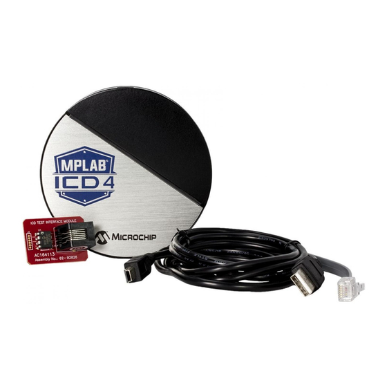
MPLAB
ICD 4 In-Circuit Debugger
®
QUICK START GUIDE
GETTING STARTED
1
Install the Latest Software
Download the MPLAB X IDE software from
automatically loads the USB drivers. Launch MPLAB X IDE.
2
Connect to Target Device
1. Connect the MPLAB ICD 4 to the computer
using the USB cable.
2. Connect external power either to the target
board or debugger.
Typical Configuration
(With On-Board Debug Circuitry)
External Microchip
OR
Power Supply (AC002018)*
Device with on-board
USB
Debugger
Alternative Configuration (Without Loss of Pins)
External Microchip
Processor Extension Pak
Power Supply (AC002018)*
USB
Debugger
External Target Board
Power Supply**
*Microchip Power Supply (AC002014) not included. Available at
www.microchipDIRECT.com.
**External target board power supply provided by user.
www.microchip.com/icd4
www.microchip.com/mplabx
External Target Board
Power Supply**
ICE circuitry
Target Device
Target Board
Standard
Adapter
Header
Device-ICE
OR
ICD Header
Device-ICE
Transition Socket
Target Board
C: 80 M: 45 Y: 0 K: 55
and install onto your computer. The installer
3
Create, Build and Run Project
1. Refer to the MPLAB X IDE User's Guide or online help
for instructions to install language tools, create or
open a project, and configure project properties.
2. Check that the configuration bits in your code match
the Recommended Settings below.
3. To execute your code in Debug mode, perform a
debug run (Debug>Debug Project). To execute
your code in Non-Debug (release) mode, perform
a run (Run>Run Project). To hold a device in Reset
after programming, use the Hold in Reset icon
in the toolbar.
Recommended Settings
Component
Setting
• OSC bits set properly
Oscillator
• Running
Power
Supplied by target
WDT
Disabled (device dependent)
Code-Protect
Disabled
Table Read Protect
Disabled
LVP
Disabled
BOD
V
> BOD V
dd
JTAG
Disabled
AV
and AV
Must be connected
dd
ss
PGCx/PGDx
Proper channel selected, if applicable
Programming
V
voltage levels meet programming spec
dd
Note: See MPLAB ICD 4 In-Circuit Debugger online help for more information.
Reserved Resources
For information on reserved resources used by the debug-
ger, see the MPLAB ICD 4 In-Circuit Debugger online help.
PMS: 7694C
min.
dd
Advertisement

Subscribe to Our Youtube Channel
Related Manuals for Microchip Technology MPLAB ICD 4


Summary of Contents for Microchip Technology MPLAB ICD 4
- Page 1 Proper channel selected, if applicable External Target Board Power Supply** Programming voltage levels meet programming spec Note: See MPLAB ICD 4 In-Circuit Debugger online help for more information. Transition Socket Reserved Resources Target Board For information on reserved resources used by the debug- *Microchip Power Supply (AC002014) not included.
- Page 2 : Depending on the overall load, it will Incorrect prevent the target from powering quickly when MPLAB ICD 4 is the source of power. Target V • Do not use capacitors on MCLR: They will prevent fast transitions of V...
- Page 3 (SCK) The Microchip name and logo, the Microchip logo, MPLAB and PIC are registered trademarks of Microchip Technology Incorporated in the U.S.A. and other countries. Arm and Cortex are registered trademarks of ARM Limited in the EU and other countries. All other trademarks mentioned herein are property of their respective companies.
Need help?
Do you have a question about the MPLAB ICD 4 and is the answer not in the manual?
Questions and answers