
Subscribe to Our Youtube Channel
Related Manuals for Microchip Technology MPLAB ICD 4


Summary of Contents for Microchip Technology MPLAB ICD 4
- Page 1 MPLAB ® ICD 4 In-Circuit Debugger User’s Guide 2017 Microchip Technology Inc. DS50002596A...
- Page 2 Serial EEPROMs, microperipherals, nonvolatile memory and analog products. In addition, Microchip’s quality system for the design Germany II GmbH & Co. KG, a subsidiary of Microchip Technology and manufacture of development systems is ISO 9001:2000 certified. Inc., in other countries.
- Page 3 For information regarding the exclusive, limited warranties applicable to Microchip products, please see Microchip’s standard terms and conditions of sale, which are printed on our sales documentation and available at www.microchip.com. Signed for and on behalf of Microchip Technology Inc. at Chandler, Arizona, USA. 2017 Microchip Technology Inc.
- Page 4 ® MPLAB ICD 4 User’s Guide NOTES: 2017 Microchip Technology Inc. DS50002596A-page 4...
-
Page 5: Table Of Contents
Part 1 – Getting Started Chapter 1. About the Debugger 1.1 Introduction ....................13 1.2 MPLAB ICD 4 In-Circuit Debugger Description ..........13 1.3 MPLAB ICD 4 In-Circuit Debugger Advantages ........... 14 1.4 MPLAB ICD 4 In-Circuit Debugger Components ......... 15 1.5 MPLAB ICD 4 Block Diagram ............... - Page 6 B.1 Introduction ....................63 B.2 Highlights ..................... 63 B.3 USB Port/Communication ................63 B.4 MPLAB ICD 4 In-Circuit Debugger .............. 64 B.5 Standard Communication Hardware ............65 B.6 ICD Test Interface Module ................68 B.7 Target Board Considerations ............... 69 Appendix C.
-
Page 7: Preface
Help. Select the Help menu, and then Topics to open a list of available online Help files. INTRODUCTION This chapter contains general information that will be useful to know before using the MPLAB ICD 4 In-Circuit Debugger. Items discussed in this chapter include: • Document Layout •... - Page 8 Part 3 – Reference • Appendix A. Debugger Function Summary – A summary of debugger functions available in MPLAB X IDE when the MPLAB ICD 4 debugger is chosen as the debug or program tool. • Appendix B. Hardware Specification –...
-
Page 9: Conventions Used In This Guide
Curly brackets and pipe Choice of mutually exclusive errorlevel {0|1} character: { | } arguments; an OR selection Ellipses... Replaces repeated text var_name [, var_name...] Represents code supplied by void main (void) user { ... 2017 Microchip Technology Inc. DS50002596A-page 9... - Page 10 ICD 4 User’s Guide ® RECOMMENDED READING This user's guide describes how to use MPLAB ICD 4 In-Circuit Debugger. Other useful documents are listed below. The following Microchip documents are available and recommended as supplemental reference resources. Multi-Tool Design Advisory (DS51764)
-
Page 11: Part 1 - Getting Started
MPLAB ICD 4 USER’S GUIDE ® Part 1 – Getting Started Chapter 1. About the Debugger .................. 13 Chapter 2. Operation....................17 Chapter 3. Debugger Usage ..................27 2017 Microchip Technology Inc. DS50002596A-page 11... - Page 12 MPLAB ICD 4 User’s Guide ® NOTES: 2017 Microchip Technology Inc. DS50002596A-page 12...
-
Page 13: Chapter 1. About The Debugger
Digital Signal Controllers (DSCs). It debugs and programs with the powerful and easy-to-use graphical user interface of MPLAB X Integrated Development Environment (IDE). The MPLAB ICD 4 is connected to your PC through a high-speed USB 3.0-compatible interface and is connected to the target with an RJ-11 connector. -
Page 14: Mplab Icd 4 In-Circuit Debugger Advantages
ICD 4 User’s Guide ® MPLAB ICD 4 IN-CIRCUIT DEBUGGER ADVANTAGES The MPLAB ICD 4 In-Circuit Debugger system provides the following advantages: Features/Capabilities: • Connects to computer via high-speed USB 2.0 (480 Mbits/s) cable • Comes with a standard Microchip debugging connector (RJ-11) and has the option to use JTAG •... -
Page 15: Mplab Icd 4 In-Circuit Debugger Components
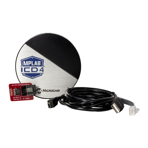
• A Mini-B USB cable to provide communication between the debugger and a computer, and to provide power from the computer to the debugger • A 6-inch modular cable (6-pin RJ-11 type) to connect the MPLAB ICD 4 unit to a header module or target board •... -
Page 16: Mplab Icd 4 Block Diagram
MPLAB ICD 4 User’s Guide ® MPLAB ICD 4 BLOCK DIAGRAM 2017 Microchip Technology Inc. DS50002596A-page 16... -
Page 17: Chapter 2. Operation
Chapter 2. Operation INTRODUCTION A simplified theory of operation of the MPLAB ICD 4 In-Circuit Debugger system is provided here. It is intended to provide enough information so that a target board can be designed that is compatible with the debugger for both debugging and programming operations. -
Page 18: Debugger To Target Communication
The debugger is connected to the target application for communication and data collection. Refer to Section B.5.1 “Connecting an RJ-11 Type Cable to an RJ-45 Socket on MPLAB ICD 4 In-Circuit Debugger” for pinout information. The power supply (not included) is connected either to the target application (preferred method) or the debugger to provide power to the target. - Page 19 Target Board FIGURE 2-2: STANDARD DEBUGGER SYSTEM – ICE DEVICE External Power supplied to either target or debugger. Processor Extension Pak Standard Header Adapter Device-ICE Transition Socket Debugger ICD Header Target Board Device-ICE 2017 Microchip Technology Inc. DS50002596A-page 19...
-
Page 20: Target Communication Connections
2.3.1 Standard Communication Target Connection Using the RJ-11 connector, the MPLAB ICD 4 In-Circuit Debugger is connected to the target device with the modular interface (six conductor) cable. The pin numbering for the connector is shown from the bottom of the target PCB in Figure 2-3. - Page 21 EXTERNALLY POWERED THROUGH DEBUGGER An alternative method of powering the target device is an external power supply connected directly to the MPLAB ICD 4. Be aware that you must also select power from the MPLAB ICD 4 debugger via MPLAB X IDE.
-
Page 22: Debugging
DEBUGGING There are two steps to using the MPLAB ICD 4 In-Circuit Debugger system as a debugger. The first requires that an application is programmed into the target device (MPLAB ICD 4 can be used for this). The second uses the internal in-circuit debug hardware of the target Flash device to run and test the application program. -
Page 23: Requirements For Debugging
Requirements for Debugging are met, these actions can be performed when the MPLAB ICD 4 In-Circuit Debugger is set as the current tool from the MPLAB X IDE menu (File>Project Properties): • When Debug>Debug Main Project is selected, the application code is programmed into the device’s memory via the ICSP protocol as described at the... - Page 24 MPLAB ICD 4 User’s Guide ® 2.5.2 Debugging Details Figure 2-6 illustrates the MPLAB ICD 4 In-Circuit Debugger system when it is ready to begin debugging. ® FIGURE 2-6: MPLAB ICD 4 IN-CIRCUIT DEBUGGER READY TO BEGIN DEBUGGING Target Internal...
-
Page 25: Programming
PROGRAMMING Use the MPLAB ICD 4 as a programmer to program a non -ICE/-ICD device, i.e., a device not on a header board. Set the MPLAB ICD 4 In-Circuit Debugger as the current tool (File>Project Properties) to perform these actions: •... - Page 26 MPLAB ICD 4 User’s Guide ® NOTES: 2017 Microchip Technology Inc. DS50002596A-page 26...
-
Page 27: Chapter 3. Debugger Usage
A tutorial is available in the MPLAB X IDE online Help that is accessible from the main menu bar Help>Tool Help Contents>MPLAB X IDE Help. 2. Connect the MPLAB ICD 4 to the computer and allow the default USB drivers to install. For more information on target connections, see Chapter 2. -
Page 28: Debug Tutorial
Refer to the MPLAB X IDE Help file titled “Getting Started with MPLAB X IDE,” and navigate through the “Tutorial” to the “Running and Debugging Code.” QUICK DEBUG/PROGRAM REFERENCE The following table is a quick reference for using the MPLAB ICD 4 In-Circuit Debugger as either a debugging or programming tool. TABLE 3-1: DEBUG VS. -
Page 29: Connecting The Target Board
3. Connect power to target or debugger. Note: In MPLAB X IDE, you can select the source from which to power the target. In order to power the target from the MPLAB ICD 4 debugger, the power supply must be connected to the debugger. -
Page 30: Setting Up The Target Board
An external power supply, Part Number AC002014, can be purchased from Microchip Direct (www.microchipdirect.com). If you have not already done so, connect the MPLAB ICD 4 to the target board using the appropriate cables (see Section 3.6 “Connecting the Target Board”). -
Page 31: Starting And Stopping Debugging
To change the style of color-coding, select Tools>Options, Fonts & Colors, Syntax tab. For more on the Editor, see NetBeans Help, IDE Basics>Basic File Features. 2017 Microchip Technology Inc. DS50002596A-page 31... -
Page 32: Breakpoints And Stopwatch
For limitations on breakpoint operation, including the general number of hardware breakpoints per device, and hardware breakpoint skidding amounts, see the online Help file in MPLAB X IDE for the MPLAB ICD 4 In-Circuit Debugger limitations. 3.10.2 Hardware or Software Breakpoint Selection To select hardware or software breakpoints: 1. - Page 33 Breakpoints halt execution of code. To determine the time between the breakpoints, use the stopwatch. Refer to the MPLAB X IDE online Help for instructions on how to set up and use break- points and the stopwatch. 2017 Microchip Technology Inc. DS50002596A-page 33...
- Page 34 MPLAB ICD 4 User’s Guide ® NOTES: 2017 Microchip Technology Inc. DS50002596A-page 34...
-
Page 35: Part 2 - Troubleshooting
MPLAB ICD 4 USER’S GUIDE ® Part 2 – Troubleshooting Chapter 4. Troubleshooting First Steps ..............37 Chapter 5. Frequently Asked Questions (FAQs) ............41 Chapter 6. Error Messages..................45 2017 Microchip Technology Inc. DS50002596A-page 35... - Page 36 MPLAB ICD 4 User’s Guide ® NOTES: 2017 Microchip Technology Inc. DS50002596A-page 36...
-
Page 37: Chapter 4. Troubleshooting First Steps
MPLAB ICD 4 USER’S GUIDE ® Chapter 4. Troubleshooting First Steps INTRODUCTION If you are having problems with MPLAB ICD 4 In-Circuit Debugger operation, start here. • The Five Questions to Answer First • Top Reasons Why You Can’t Debug •... -
Page 38: Top Reasons Why You Can't Debug
12. Incorrect brown-out voltage. Brown-out Detect voltage is greater than the operating voltage V . This means the device is in Reset and cannot be debugged. 13. Incorrect connections. You have not followed the guidelines in Chapter 2. “Operation”. 2017 Microchip Technology Inc. DS50002596A-page 38... -
Page 39: Other Things To Consider
FIGURE 4-1: PROGRAM SPEED OPTION 6. If the MPLAB X IDE or MPLAB IPE cannot communicate with the MPLAB ICD 4 debugger (LEDs continually alternate between purple and blue), perform the fol- lowing steps to force the debugger into Boatload mode: a) Disconnect the Mini-B USB cable from the debugger. - Page 40 When complete, the LEDs are steady on blue and the debugger is ready for operation. Refer to Section B.4.2 “Indicator Lights (LEDs)” for more information on LED modes and bootloader errors. If the problem persists, contact Microchip Support. 2017 Microchip Technology Inc. DS50002596A-page 40...
-
Page 41: Mplab ® Icd 4 User's Guide
• What’s Wrong? HOW DOES IT WORK? • What's in the silicon that allows it to communicate with the MPLAB ICD 4 In-Circuit Debugger? MPLAB ICD 4 In-Circuit Debugger can communicate with Flash silicon via the ICSP interface. It uses the debug executive located in test memory. For legacy 8-bit devices, the debug executive resides in Program memory. -
Page 42: What's Wrong
• Is it possible to debug a dsPIC DSC running at any speed? The MPLAB ICD 4 is capable of debugging at any device speed as specified in the device’s data sheet. - Page 43 Frequently Asked Questions (FAQs) while (1); void __attribute__((__interrupt__)) _AltOscillatorFail(void) INTCON1bits.OSCFAIL = 0; while (1); - Use ASSERTs. For example: ASSERT (IPL==7) 2017 Microchip Technology Inc. DS50002596A-page 43...
-
Page 44: Microchip Technology Inc. Ds50002596A
MPLAB ICD 4 User’s Guide ® NOTES: 2017 Microchip Technology Inc. DS50002596A-page 44... -
Page 45: Chapter 6. Error Messages
Chapter 6. Error Messages INTRODUCTION The MPLAB ICD 4 In-Circuit Debugger produces various error messages; some are specific, some are informational, and others can be resolved with general corrective actions. In general, read any instructions under your error message. If those fail to fix the problem or if there are no instructions, refer to the following sections. - Page 46 2. Select Halt to stop any running applications. Then, try to deselect the debugger again. 3. Unplug the debugger from the computer. Then, try to deselect the debugger again. 4. Shut down MPLAB IDE X. 2017 Microchip Technology Inc. DS50002596A-page 46...
- Page 47 DEVICE_ID_REVISION=Device Id Revision DEVICE_ID=Device Id DEVID_MISMATCH=Target Device ID (0x%x) is an Invalid Device ID. Please check your connections to the Target Device. 2017 Microchip Technology Inc. DS50002596A-page 47...
- Page 48 FIRMWARE_DOWNLOAD_TIMEOUT=REAL ICE 4 timeout out during the firmware download process. FLASH_DATA_MEMORY=Flash data memory FLASH_DATA=flash data FPGA_VER=FPGA Version FRCINDEBUG_NEEDS_CLOCKSWITCHING=To use FRC in debug mode the clock switching configuration bits set- ting must be enabled. Please enable clock switching and retry the requested operation. 2017 Microchip Technology Inc. DS50002596A-page 48...
- Page 49 "Memories to Program" property page. MEM_RANGE_ERROR_STARTADDR_NOT_ALIGNED=Invalid program range received: start address %s is not aligned on a proper 0x%x address boundary. Please check the manual program ranges on the debug tool's, "Memo- ries to Program" property page. 2017 Microchip Technology Inc. DS50002596A-page 49...
- Page 50 "Memories to Program" property page. PRESERVE_MEM_RANGE_ERROR_BAD_START_ADDR=Invalid preserve range start address %s received. Please check the manual program ranges on the debug tool's, "Memories to Program" property page. 2017 Microchip Technology Inc. DS50002596A-page 50...
- Page 51 You may continue running but certain run time features may no longer work properly. RUN_TARGET_FAILED=Unable to run the target device. RUNNING=Running SERIAL_NUM=Serial Number:\n SETTING_SWBPS=Setting software breakpoints..STACK=stack START_AND_END_ADDR=start address = 0x%x, end address = 0x%x START=start TARGET_DETECTED=Target voltage detected 2017 Microchip Technology Inc. DS50002596A-page 51...
- Page 52 Programming check box of the Program Options Option Category pane (low voltage programming is not valid for debugging operations). USERID_MEMORY=User Id Memory USERID=user Id VERIFY_COMPLETE=Verification successful. VERIFY_FAILED=Verify failed VERSIONS=Versions VOLTAGES=Voltages WOULD_YOU_LIKE_TO_CONTINUE=Would you like to continue? 2017 Microchip Technology Inc. DS50002596A-page 52...
-
Page 53: General Corrective Actions
2. Ensure that the cable(s) are of the correct length. 6.3.3 Debugger to Computer Communication Error Actions If the MPLAB ICD 4 In-Circuit Debugger and MPLAB IDE X are not communicating with each other. 1. Unplug, and then plug in, the debugger. -
Page 54: Information Messages
5. If using a USB hub, make sure it is powered. 6. Make sure the USB drivers are loaded. 6.3.6 Debug Failure Actions The MPLAB ICD 4 In-Circuit Debugger was unable to perform a debugging operation. There are numerous reasons why this might occur. See Chapter 4. “Troubleshooting First Steps”. -
Page 55: Part 3 - Reference
MPLAB ICD 4 USER’S GUIDE ® Part 3 – Reference Appendix A. Debugger Function Summary............... 57 Appendix B. Hardware Specification................63 Appendix C. Revision History..................71 2017 Microchip Technology Inc. DS50002596A-page 55... - Page 56 MPLAB ICD 4 User’s Guide ® NOTES: 2017 Microchip Technology Inc. DS50002596A-page 56...
-
Page 57: Appendix A. Debugger Function Summary
Use the Project Properties dialog to select or switch debuggers for a project. To switch you must have more than one MPLAB ICD 4 In-Circuit Debugger connected to your computer. MPLAB X IDE will differentiate between the two by displaying two different serial numbers. - Page 58 This memory is read from the target and overlayed with existing MPLAB X IDE memory. Ensure that code is NOT code protected. * If you receive a programming error due to an incorrect range, ensure the range does not exceed available/remaining device memory. 2017 Microchip Technology Inc. DS50002596A-page 58...
- Page 59 Select either Low, Normal or High. The default is Normal. A.3.4 Freeze Peripherals Select from the list of peripherals to freeze or not freeze on program halt. The available peripherals are device dependent. 2017 Microchip Technology Inc. DS50002596A-page 59...
- Page 60 Use Latest Firmware Check to use the latest firmware. Uncheck to select the firmware version. Firmware File Click in the right-hand text box to search for a firmware file (.jam) to associate with the debugger. 2017 Microchip Technology Inc. DS50002596A-page 60...
- Page 61 Checking this check box will let the application run at the slow speed but debug at the faster FRC speed. Reprogram after changing this setting. Note: Peripherals that are not frozen will operate at the FRC speed while debugging. 2017 Microchip Technology Inc. DS50002596A-page 61...
- Page 62 MPLAB ICD 4 User’s Guide ® 2017 Microchip Technology Inc. DS50002596A-page 62...
-
Page 63: Appendix B. Hardware Specification
Target Board Considerations USB PORT/COMMUNICATION The MPLAB ICD 4 In-Circuit Debugger is connected to the host computer via a USB port, version 2.0 compliant. The USB connector is located on the side of the debugger. The system is capable of reloading the firmware via the USB interface. -
Page 64: Mplab Icd 4 In-Circuit Debugger
• two LEDs B.4.2 Indicator Lights (LEDs) The expected start-up sequence for the MPLAB ICD 4 debugger is: 1. Purple - steady on for approximately 3 seconds 2. Blue - flashing for approximately 2 seconds while the debugger runs a power-on self-test 3. -
Page 65: Standard Communication Hardware
RJ-11 type cable to the type cable to the RJ-45 Socket, refer to target, refer to Section B.5.1 “Connecting an RJ-11 Section B.5.2 “Standard Type Cable to an RJ-45 Socket on Communication”. MPLAB ICD 4 In-Circuit Debugger”. 2017 Microchip Technology Inc. DS50002596A-page 65... - Page 66 The actual power comes from the MPLAB ICD 4 In-Circuit Debugger system, as the V sense line is used as a reference only to track the target voltage. The V connection is isolated with an optical switch.
-
Page 67: Hardware Specification
Connector on Target Board Ground Target Bottom View of Modular Connector Pinout on Target Board B.5.3.2 MODULAR PLUG SPECIFICATION • Manufacturer, Part Number – AMP Incorporated, 5-554710-3 • Distributor, Part Number – Digi-Key, A9117ND 2017 Microchip Technology Inc. DS50002596A-page 67... -
Page 68: Icd Test Interface Module
ICD 4 3. Reconnect the debugger to the computer. 4. Power the MPLAB ICD 4 through either the USB cable to the computer. 5. Launch MPLAB X IDE. Ensure that all existing projects are closed. 6. Select Debug>Run Debugger/Programmer Self Test, then, select the specific “ICD 4”... -
Page 69: Target Board Considerations
Depending on the type of debugger-to-target communication that is used, there are some considerations for target board circuitry: • Section 2.3.2 “Target Connection Circuitry” • Section 2.3.4 “Circuits That Will Prevent the Debugger From Functioning” 2017 Microchip Technology Inc. DS50002596A-page 69... - Page 70 MPLAB ICD 4 User’s Guide ® NOTES: 2017 Microchip Technology Inc. DS50002596A-page 70...
-
Page 71: Appendix C. Revision History
MPLAB ICD 4 USER’S GUIDE ® Appendix C. Revision History Revision A (August 2017) Initial release of this document. 2017 Microchip Technology Inc. DS50002596A-page 71... - Page 72 MPLAB ICD 4 User’s Guide ® NOTES: 2017 Microchip Technology Inc. DS50002596A-page 72...
-
Page 73: Support
A FAQ and registration details are available on the page, which can be opened by selecting the link above. 2017 Microchip Technology Inc. DS50002596A-page 73... -
Page 74: Customer Support
• Emulators – The latest information on the MPLAB REAL ICE™ emulator. • In-Circuit Debuggers – The latest information on Microchip in-circuit debuggers. These include the MPLAB ICD 3 and MPLAB ICD 4 in-circuit debuggers and PICkit™ 3 debug express. -
Page 75: Glossary
For example, in the following code, are members of an anonymous structure inside the union caster union castaway int intval; struct { char lo; //accessible as caster.lo char hi; //accessible as caster.hi } caster; 2017 Microchip Technology Inc. DS50002596A-page 75... - Page 76 Breakpoint Hardware Breakpoint: An event whose execution will cause a halt. Software Breakpoint: An address where execution of the firmware will halt. Usually achieved by a special break instruction. 2017 Microchip Technology Inc. DS50002596A-page 76...
- Page 77 A Configuration bit may or may not be preprogrammed. Control Directives Directives in assembly language code that cause code to be included or omitted based on the assembly-time value of a specified expression. See Central Processing Unit. 2017 Microchip Technology Inc. DS50002596A-page 77...
- Page 78 Download is the process of sending data from a host to another device, such as an emulator, programmer or target board. DWARF Debug With Arbitrary Record Format. DWARF is a debug information format for ELF files. 2017 Microchip Technology Inc. DS50002596A-page 78...
- Page 79 In extended microcontroller mode, on-chip program memory as well as external memory is available. Execution automatically switches to external if the program memory address is greater than the internal memory space of the PIC18 device. 2017 Microchip Technology Inc. DS50002596A-page 79...
- Page 80 A pointer that references the location on the stack that separates the stack-based arguments from the stack-based local variables. Provides a convenient base from which to access local variables and other values for the current function. 2017 Microchip Technology Inc. DS50002596A-page 80...
- Page 81 Integrated Development Environment, as in MPLAB IDE/MPLAB X IDE. Identifier A function or variable name. IEEE Institute of Electrical and Electronics Engineers. 2017 Microchip Technology Inc. DS50002596A-page 81...
- Page 82 An expression that refers to an object that can be examined and/or modified. An l-value expression is used on the left-hand side of an assignment. Latency The time between an event and its response. Library/Librarian See Archive/Archiver. 2017 Microchip Technology Inc. DS50002596A-page 82...
- Page 83 (possibly interspersed with data). The collection of all possible instructions for a particular processor is known as its “instruction set”. Machine Language A set of instructions for a specific central processing unit, designed to be usable by a processor without being translated. 2017 Microchip Technology Inc. DS50002596A-page 83...
- Page 84 Module The preprocessed output of a source file after preprocessor directives have been executed. Also known as a translation unit. MPASM™ Assembler Microchip Technology’s relocatable macro assembler for PIC microcontroller devices, ® KeeLoq devices and Microchip memory devices. MPLAB Language Tool for Device Microchip’s C compilers, assemblers and linkers for specified devices.
- Page 85 In Non-Extended mode, the compiler will not utilize the extended instructions nor the indexed with literal offset addressing. Non Real Time Refers to the processor at a breakpoint or executing single-step instructions or MPLAB IDE/MPLAB X IDE being run in simulator mode. 2017 Microchip Technology Inc. DS50002596A-page 85...
- Page 86 PC Host Any PC running a supported Windows operating system. Persistent Data Data that is never cleared or initialized. Its intended use is so that an application can preserve data across a device Reset. 2017 Microchip Technology Inc. DS50002596A-page 86...
- Page 87 MPLAB IDE/MPLAB X IDE – The memory area in a device where instructions are stored. Also, the memory in the emulator or simulator containing the downloaded target application firmware. 16-bit assembler/compiler – The memory area in a device where instructions are stored. 2017 Microchip Technology Inc. DS50002596A-page 87...
- Page 88 The concept that a function or macro, having been defined, can call itself. Great care should be taken when writing recursive macros; it is easy to get caught in an infinite loop where there will be no exit from the recursion. 2017 Microchip Technology Inc. DS50002596A-page 88...
- Page 89 Serialized Quick Turn Programming Serialization allows you to program a serial number into each microcontroller device that the Device Programmer programs. This number can be used as an entry code, password or ID number. 2017 Microchip Technology Inc. DS50002596A-page 89...
- Page 90 Memory used by an application for storing return addresses, function parameters, and local variables. This memory is dynamically allocated at runtime by instructions in the program. It allows for reentrant function calls. Stack, Compiled 2017 Microchip Technology Inc. DS50002596A-page 90...
- Page 91 The system window control is located in the upper left corner of windows and some dialogs. Clicking on this control usually pops up a menu that has the items “Minimize,” “Maximize,” and “Close.” 2017 Microchip Technology Inc. DS50002596A-page 91...
- Page 92 Upload The Upload function transfers data from a tool, such as an emulator or programmer, to the host computer or from the target board to the emulator. 2017 Microchip Technology Inc. DS50002596A-page 92...
- Page 93 A timer on a PIC microcontroller that resets the processor after a selectable length of time. The WDT is enabled or disabled and set up using Configuration bits. Workbook For MPLAB SIM stimulator, a setup for generation of SCL stimulus. 2017 Microchip Technology Inc. DS50002596A-page 93...
- Page 94 MPLAB ICD 4 User’s Guide ® NOTES: 2017 Microchip Technology Inc. DS50002596A-page 94...
-
Page 95: Index
Force Bootload Mode..........39 Programming............17 Freeze on Halt ............42 Command-line........... 28 Freeze Peripherals Setup ........59 Production........... 13 Project Properties Dialog ........27 Pull-ups ..............22 General Corrective Actions ........53 2017 Microchip Technology Inc. DS50002596A-page 95... - Page 96 USB drivers .............. 27 Using ICE Devices ........... 30 Using Production Devices ........30 Vcap ................. 21 Vdd ..............20 Vpp ..............20 Vss ..............20 Watchdog Timer ..........23 Web Site, Microchip ..........73 2017 Microchip Technology Inc. DS50002596A-page 96...
- Page 97 Index NOTES: 2017 Microchip Technology Inc. DS50002596A-page 97...
-
Page 98: Worldwide Sales And Service
Thailand - Bangkok Tel: 408-735-9110 Sweden - Stockholm Tel: 86-29-8833-7252 Tel: 66-2-694-1351 Tel: 408-436-4270 Tel: 46-8-5090-4654 Fax: 86-29-8833-7256 Fax: 66-2-694-1350 Canada - Toronto UK - Wokingham Tel: 905-695-1980 Tel: 44-118-921-5800 Fax: 905-695-2078 Fax: 44-118-921-5820 2017 Microchip Technology Inc. DS50002596A-page 98 11/07/16...
Need help?
Do you have a question about the MPLAB ICD 4 and is the answer not in the manual?
Questions and answers