
Related Manuals for oGrow OGAL-866


Summary of Contents for oGrow OGAL-866
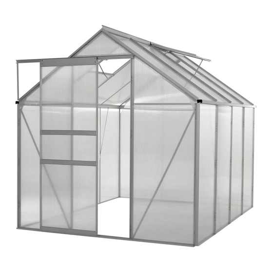
- Page 2 Step 1: This procedure will assist you with assembling the OGrow Walk-In 6 ft. by 8 ft. Lawn and Garden Greenhouse with Heavy Duty Aluminum Frame. Step 2: To complete this procedure, you will need a Phillips Screwdriver, Needle Nose Pliers, and Gloves. Option- ally, you may need a Step Ladder, a Caulking Gun, and Silicone Glass Glue.
- Page 3 Step 4: Insert (2) Bolts (F - C 1 4) into (F - C 0 2 A) and (F - C 0 2). Attach (1) Nut (F - C 1 4) to each Bolt. Do not fully tighten. Step 5: Slide (F - 0 5) into position and make sure the Bolts slide into the grooves.
- Page 4 Step 7: Insert (2) Bolts (F - C 1 4) into (F - C 0 2 A) and (F - C 0 2). Attach (1) Nut (F - C 1 4) to each Bolt. Do not fully tighten. Step 8: Slide (F - 0 5) into position and make sure the Bolts slide into the grooves.
- Page 5 Step 10: Attach (F - 2 9) and (F - 1 7) to (F - 0 5) using (1) Bolt (F - C 1 4) and (1) Nut (F - C 1 4). Leave a three-quar- ter inch distance from the top of (F - 0 5) to the Bolt. Repeat for the other 3 corners.
- Page 6 Step 13: Insert (2) Bolts into each (F - 2 3) beam. Attach (F - 2 3) to (F - 1 7) using the upper Bolt. Tighten the Nut to the Bolt. Note: Leave a three-quarter inch distance from the edge of (F - 1 7) to the top of (F - 2 3).
- Page 7 Step 16: Attach one section of the assembly to (F - 0 3 B) and (F - 0 4). Tighten all Nuts of the assembly. Note: Make sure to always support the assembly until the structure is able to support itself. Step 17: Attach the other section of the assembly to (F - 0 3 B) and (F - 0 4).
- Page 8 Step 19: Connect (F - 0 5), (F - 1 9 B), and (F - 1 8) using the upper Bolt. When the notch on (F - 1 9 B) is aligned with the top of (F - 0 5), attach (1) Nut onto the Bolt. Do not fully tighten the Nut.
- Page 9 Step 22: Attach (1) Bolt into (F - 3 0) and (F - 0 4) using (1) Nut. Repeat for other side. Step 23: Tighten all the Nuts in the indicated locations. Note: Structure should be self supporting at this step, if not, tighten all loose Nuts.
- Page 10 Step 25: Repeat for the other side. Step 26: Connect (F - 1 7) to (F - 1 9 B) using (1) Nut. Repeat on the other side. Do not fully tighten the Nuts. Step 27: Attach (1) Bolt into (1) (F - 3 0) and (F - 0 3 B) using (1) Nut.
- Page 11 Step 28: Attach (F - 4 1) to (F- 2 3) using (2) Nuts and the pre- viously installed (2) Bolts. Make sure the shelf part is facing upward. Repeat on the other side. Step 29: Insert (F – 0 8), (F – 0 9), (F – 1 0), and (F – 1 1) into the Bolts at each location.
- Page 12 Step 31: Insert (1) Bolt into (F – 0 9). Connect (F – 1 8) and (F – 0 9) using (1) Nut. Step 32: Insert (1) Bolt into (F – 1 0). Connect (F – 1 7) and (F –...
- Page 13 Step 34: Tighten the Nuts at the indicated locations. Step 35: Insert (2) Bolts and (2) Nuts into (F - C 0 2 A) in the indicated areas. Do not fully tighten the Nuts. Step 36: Insert (F - 2 3) into the Bolt on the base. Slide (1) Bolt into (F –...
- Page 14 Step 37: Insert (F - 2 3) into the Bolt on the base. Slide (1) Bolt into (F – 2 3). Attach (F - 2 3) to (F - 4 1) using (1) Nut. Tighten all the Nuts. Step 38: When assembling the Panels, the UV-protected side of the sheet is covered with Opal White Film and must face towards the sun when attached to the Greenhouse.
- Page 15 Step 40: Slide (8) (F – 3 4) Panels into the grooves of the beams at each of the designated areas. Step 41: Remove the Opal White Film from (2) (F - 3 2) Panels. Note: Make sure the side with the Opal White Film will face the outside.
- Page 16 Step 43: Remove the Opal White Film from (2) (F - 3 3) Panels. Note: Make sure the side with the Opal White Film will face the outside. Step 44: Slide (2) (F – 3 3) Panels into the grooves of the beams at each of the designated areas.
- Page 17 Step 46: Slide (1) (F – 3 1) Panel into the grooves of the beams at the designated area. Step 47: Insert the Bolts and Nuts into each hole of (F – C 0 6) and (F - C 0 6 A). Do not fully tighten the Nuts. Step 48: Slide the Bolts on (F - C 0 6 A) into the grooves of (F –...
- Page 18 Step 49: Slide the Bolts on (F - C 0 6) into the grooves of (F - 2 3) and (F – 0 5). Tighten the Nuts. Step 50: Insert (1) Bolt and (1) Nut into each hole in (F - C 0 6) and (F - C 0 6 A).
- Page 19 Step 52: Insert (2) Bolts and (2) Nuts into the holes on the top edge of (F – 1 9 B) as shown. Do not fully tighten the Nuts. Step 53: Insert (F – 0 6) and (F – 0 7) through the Bolts in the (2) (F –...
- Page 20 Step 55: Insert (F – 0 6) and (F – 0 7) through the Bolts in (F – 1 9 B) and (F – C 0 6 A) / (F – C 0 6) on the other side. Tighten the Nuts. Step 56: Slide (2) Bolts into the grooves of (F –...
- Page 21 Step 58: Attach (F – C 0 7) and (F – C 0 7 A) with (F – 4 3) using (6) Bolts and (6) Nuts. Step 59: Insert (1) Bolt into (F – 0 6) and (F – 0 7) on each side to secure (F –...
- Page 22 Step 61: Slide (F – 4 0) Panel into the angle joining (F – 0 6) and (F – 0 7). Step 62: Attach the (F – 1 2) and (F – 1 9) Panels using (2) Bolts and (2) Nuts. Step 63: Insert (6) Bolts into (F - C 0 6) and (F - C - 0 6 A) and secure with (6) Nuts.
- Page 23 Step 64: Slide (1) Bolt into (2) (F - 2 4) Beams. These Bolts will be used in a later step. Step 65: Slide (1) Bolt into each (F - 2 4) Beams and insert the Bolts into the holes of (F – C 0 7) and (F – C 0 7 A). Tighten (1) Nut to each Bolt.
- Page 24 Step 67: Remove the Opal White Film from (7) (F - 3 5) Panels. Note: Make sure the side with the Opal White Film will face the outside. Step 68: Slide (7) (F – 3 5) Panels into each of the designated slots.
- Page 25 Step 70: Slide (1) (F – 3 6) Panel into the designated slots. Step 71: Connect (F – C 0 5) and (F – C 0 5 A) to (F – C 0 6) and (F – C 0 6 A) with the (6) Bolts and (6) Nuts. Re- peat for the other side.
- Page 26 Step 73: Attach (2) (F – 2 6) to (1) (F - 2 7). Step 74: Remove the Opal White Film from (1) (F - 3 7) Panel. Note: Make sure the side with the Opal White Film will face the outside. Step 75: Slide (1) (F - 3 7) Panel into the Window Assembly.
- Page 27 Step 76: Slide (1) (F – 2 5) over the top edge of (F – 3 7). Step 77: Secure the 4 corners with (4) Bolts and (4) Nuts. Step 78: Attach (F – 2 0) to (F – 2 7) using (2) Screws (F – C 1...
- Page 28 Step 79: Using a Step Ladder, slide the Window into the groove on (F – C 0 7). Make sure the Window pivots up and down correctly. Step 80: Slide (3) Bolts into the grooves of (F – 1 3). Step 81: Attach (F –...
- Page 29 Step 82: Attach (F – 2 1) to (F - 1 3) and (F – 0 7) using the pre- viously installed Bolt, (1) Bolt, and (2) Nuts. Step 83: Remove the Opal White Film from (2) (F - 3 8) and (1) (F - 3 9) Panels.
- Page 30 Step 85: Slide (1) (F – 3 9) Panel into the middle slot. Step 86: Attach (1) (F – 1 6 B) to the other side of the (F – 1 5) Beams. Secure with (4) Screws (F – C 1 5 A). Step 87: Slide (2) (F –...
- Page 31 Step 88: Cap the top and bottom of the Door with (2) (F – 1 4 Step 89: Secure the remaining (F – 1 6 B) using (4) Screws (F – C 1 5 A). Step 90: Insert (1) (F – 2 2 B) into the top of (F – 1 6 B). Secure (F - 2 2 B) with (1) Screw (F –...
- Page 32 Step 91: Insert (1) (F – 2 2 B) into the bottom of (F – 1 6 B). Secure (F - 2 2 B) with (1) Screw (F – C 1 6). Repeat on the other side. Step 92: Slide assembled Door into position. Ensure that (F - 2 2 B) aligns to the middle groove of (F –...
- Page 33 Step 94: Insert (4) (G – P 1) units into the top corners of the front and back walls of the Greenhouse, sliding the rectangular section into (F - C 0 5) / (F – C 0 5 A) Panel. Step 95: Slide (1) (G –...
- Page 34 Step 97: Cap (F – 1 3) with (G – P 3 L) at the left end and (G – P 3 R) at the right end. Secure both Caps with (2) Bolts and (2) Nuts. Step 98: Note: When the Window is closed, the Handle of (F – 2 0) can be rotated to the right and fixed in place.
- Page 35 You can buy them locally. Only use Silicone Glass Glue suitable for Aluminum. Step 101: Congratulations, this completes the assembly of OGrow Walk-In 6 ft. by 8 ft. Lawn and Garden Green- house with Heavy Duty Aluminum Frame.