Table of Contents
Advertisement
Available languages
Available languages
Use & Care Guide
Manual de Uso y Cuidado
English / Español
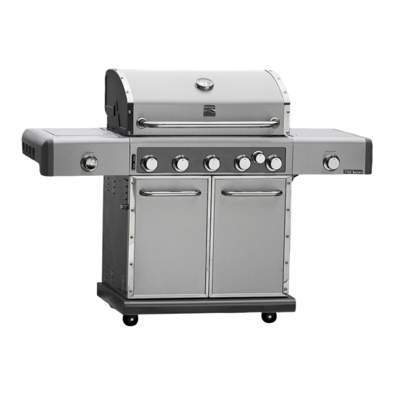
Kenmore Elite
Liquid Propane Gas Grill
Parrilla a gas de propane liquido
Model/Modelo:
Item / Artículo:
P/N 50600322A
Sears Brands Management Corporation
Hoffman Estates, IL 60179 U.S.A.
www.kenmore.com
www.sears.com
www.kmart.com
®
146.03358410 – Stainless Steel / Acero Inoxidable
146.30212510 – Carbon Grey Metallic / Carbono Gris Metálico
146.30213510 – Maroon Metallic / Marrón Metálico
640-06201888-2 –Stainless Steel / Acero Inoxidable
640-03165406-4 –Carbon Grey Metallic / Carbono Gris Metálico
640-03165407-2 –Maroon Metallic / Marrón Metálico
®
Advertisement
Table of Contents

Related Manuals for Kenmore 700 Series


Summary of Contents for Kenmore 700 Series
- Page 1 Use & Care Guide Manual de Uso y Cuidado English / Español Kenmore Elite ® Liquid Propane Gas Grill Parrilla a gas de propane liquido Model/Modelo: 146.03358410 – Stainless Steel / Acero Inoxidable 146.30212510 – Carbon Grey Metallic / Carbono Gris Metálico 146.30213510 –...
- Page 2 The Kenmore brand has over a 100-year history of providing innovative solutions that enable our members and customers to get more out of their lives. During this time, the Kenmore brand has evolved through technology, style and the specific needs of every generation. Yet, one constant remains –...
- Page 3 Installation Safety Precautions Call Grill Service Center For Help And Parts • Please read this User’s Manual in its entirety before using If you have questions or need assistance during assembly, the grill. please call 1-888-287-0735. You will be speaking to a •...
- Page 4 WARNING Repair Protection Agreements ® Congratulations on making a smart purchase. Your new Kenmore This grill is rated at 96,000 BTU. This is more than one product is designed and manufactured for years of dependable standard 20 lb. LP tank can deliver at once, especially operation.
- Page 5 WARRANTY KENMORE ELITE LIMITED WARRANTY WITH PROOF OF SALE, the following warranty coverage applies when this appliance is correctly installed, operated and maintained according to all supplied instructions. To arrange for in-home warranty service, call 1-800-4-MY-HOME® (1-800-469-4663) FOR TWO YEARS from the date of sale this appliance is warranted against defects in material or workmanship. A defective appliance will receive free repair or replacement at option of seller.
- Page 6 LP Cylinder USE AND CARE • The LP cylinder used with your grill must meet the following requirements: DANGER • Use LP cylinders only with these required measurements: 12" (30.5cm) (diameter) x 18" (45.7 cm) (tall) with 20 lb. (9 kg.) Capacity maximum.
- Page 7 LP Tank Exchange Connecting Regulator To The LP Tank • Many retailers that sell grills offer you the option of replacing 1. LP tank must be properly secured onto grill. (Refer to your empty LP tank through an exchange service. Use only those assembly section.) reputable exchange companies that inspect, precision fill, test 2.
- Page 8 Leak Testing Valves, Hose and Regulator 1.Turn all grill control knobs to OFF. 2.Be sure regulator is tightly connected to LP tank. 3.Completely open LP tank valve by turning OPD hand wheel counterclockwise. If you hear a rushing sound, turn gas off immediately.
- Page 9 Safety Tips WARNING ▲ Before opening LP cylinder valve, check the coupling nut for tightness. ▲ When grill is not in use, turn off all control knobs and LP cylinder For Safe Use of Your Grill and to Avoid Serious valve.
- Page 10 Burner Flame Check WARNING • Remove cooking grates and heat diffusers. Light burners, turn knobs from HI to LO. You should see a smaller flame in LO position than seen on HI. Perform burner flame check Turn controls and gas source or tank OFF when not on sideburner, also.
- Page 11 Cleaning the Burner Assembly WARNING CAUTION Follow these instructions to clean and/or replace parts of burner assembly or if you have trouble igniting grill. 1. Turn gas off at control knobs and LP cylinder. SPIDER ALERT! SPIDER ALERT! SPIDER ALERT! 2.
- Page 12 Indirect Cooking Food Safety Poultry and large cuts of meat cook slowly to perfection on the grill Food safety is a very important part of enjoying the outdoor by indirect heat. Place food over unlit burner(s); the heat from lit cooking experience.
- Page 13 Natural Gas Conversion Kit To purchase Natural Gas Conversion Parts call sears at 1-800-4-MY-HOME ® Natural gas conversion kit (Manufacturer Part NO.: 30800339 Your grill can be converted to natural gas with this conversion kit by a qualified gas technician only. In order to convert this grill the technician will need this conversion kit.
- Page 14 Notes Gas Requirements LP Gas For Natural Gas Connection If your grill is for LP Gas, the regulator supplied is set for Preparing: an 11-in. Water column (WC) and is for use with LP gas 1. Turn off gas supply, and then remove cap on gas only.
- Page 15 PARTS LIST Description Part Number Description Part Number Description Lid, Side Burner 41500041 Regulator 50600233 HEAT DIFFUSERS Rotate Rod, Side Burner 41500205 Hose Retaining Clip 30800226 COOKING GRATE End Cap, Right Side Shelf 30800206 Control Knob Bezel 40900036 SWING AWAY GRATE CLIP, F/ GREASE CUP Right Side Shelf 50600033...
- Page 16 PARTS LIST Description Part Description Part Number Description Number HEAT DIFFUSERS Left Side Panel (Carbon Grey 63-1 50600045A Motor 50600210 COOKING GRATE Metallic) SWING AWAY GRATE Left Side Panel (Maroon 63-2 50600045B Rotisserie Rod 50600206 Metallic) CLIP, F/ GREASE CUP GREASE CUP 63-3 Left Side Panel (Silver)
- Page 17 DIAGRAM PARTS LIST 146.03358410 • 17...
- Page 18 BEFORE ASSEMBLY NOTICE: Once you have unpacked the grill according to the STOP SHEET instructions, check all grill parts against the pictures on this and the following two pages. If any parts are missing or damaged, call 1-888-287-0735 18·146.03358410...
- Page 19 BEFORE ASSEMBLY 146.03358410• 19...
- Page 20 BEFORE ASSEMBLY 20·146.03358410...
- Page 21 ASSEMBLY CAREFULLY READ AND PERFORM ALL ASSEMBLY INSTRUCTIONS ON THE FOLLOWING PAGES. Tools Required: Adjustable wrench (not provided) #2 and #3 Philips Screwdriver and Slotted Screwdriver (not provided) The following hardware is provided in blister pack for convenient use. M4X10 Screws M4X12 Screws Qty: 2 pcs Qty: 2 pcs...
- Page 22 Left Side Shelf Assembly □ Hang shelf onto brackets on left side of firebox. (A) □ Attach shelf to firebox from inside with (2) M6x13 screws. (B) □ Attach shelf to firebox from outside with (3) M6x13 screws and (1) M4x12 screw. (C) M6X13 screws Qty: 5 pcs M4X12 screws Qty: 1 pc 22·146.03358410...
- Page 23 Right Side Shelf Assembly □ Hang shelf onto brackets on right side of firebox. (A) □ Attach shelf to firebox from inside with (2) M6x13 screws. (B) □ Attach shelf to firebox from outside with (3) M6x13 screws and (1) M4x12 screw. (C) M6X13 screws Qty: 5 pcs M4X12 screws Qty: 1 pc 146.03358410·23...
- Page 24 Left Side burner □ Remove plastic packaging from side burner valve. Remove side burner grate from within side burner shelf. □ Connect flat igniter wire tip to the igniter pin on the side burner valve. (A & B) □ Remove the 2 pre-installed screws from the valve control stem and set them aside. (C) □...
- Page 25 146.03358410·25...
- Page 26 Right Side Searing burner □ Remove plastic packaging from searing burner valve. Remove searing burner grate from within searing burner shelf. □ Connect flat igniter wire tip to the igniter pin on the searing burner valve. (A & B) □ Remove the 2 pre-installed screws from the valve control stem and set them aside. (C) □...
- Page 27 146.03358410·27...
- Page 28 Tank Baffle Assembly □ Insert tank baffle bar tip with oval hole over oval tab on underside of grease tray bracket (A). Turn bar to right to lock tip in place (B). □ □ Secure other tip of bar to grill bottom shelf with (1) M4x10 screw (C). Repeat above steps for other tank baffle bar (D).
- Page 29 Grease Tray and Grease Box □ From front of grill, slide grease tray onto grease tray brackets underneath firebox (A). Make sure grease drainage hole is on left side (B). □ Slide grease box into grease box bracket as shown. (C)(D) CAUTION Failure to install grease box will cause hot grease to drip from bottom of grill...
- Page 30 Heat Diffusers, Cooking Grate and Warming Rack □ Place heat diffusers over burners. The heat diffusers will fit in firebox in either direction. Fit tabs in firebox front through slots in diffuser tips. Fit diffuser tips inside tabs in firebox rear. (A) □...
- Page 31 Door Adjustment (Left door shown) □ Remove the screw cover from the upper and lower hinges to expose the adjustment screws (A). □ To adjust the gap between the doors, turn the outer screws counterclockwise to increase the gap, and clockwise to decrease the gap (A & B). □...
- Page 32 Gas Tank Installation □ LP tank is sold separately. □ Place LP tank onto fuel gauge with tank collar opening facing to the left as shown. First hang tank collar opening over hook in face of gauge. Then rotate gauge latch down over collar and tighten wing nut to secure collar in place.
- Page 33 Safety Notice - Lock Caster Brakes □ When the grill in the desired location, lock the caster brakes; this will help the grill stay in place for safe operation. 146.03358410·33...
- Page 34 Rotisserie Kit Assembly (Rotisserie motor on left side as shown) □ Remove warming rack from firebox. Insert motor support into motor support bracket preassembled to left side of firebox (A). □ Insert rotisserie motor onto motor support (B). Make sure to insert motor with power cord at bottom.
- Page 35 Batteries □ Unscrew the igniter caps from the cart side panels as shown below (A & B). □ Insert (1) AA battery into each battery slot with the positive (+ ) battery pole facing outward (C). Screw igniter caps back on (D). □...
- Page 36 NOTES Control Panel LED Light Battery Assembly □ Lift battery module out of battery box on inside of left cart panel (A). Disconnect plug between wires to free the module for battery insertion (B). □ Remove battery module cover (C). Insert (4) AA batteries into battery slots in orientation as shown (D).
- Page 37 Note: If the lamps on the inside rear of the firebox do not work, follow the steps below to replace them. Remove the rear panel screw and nuts Take the rear panel out Loosen the lamp from lamp seat. Remove the lamp screw and nuts Take the lamp out from rear of lamp seat Press the button to remove the lamp glass 146.03358410·37...
- Page 38 Remove the rejected lamp bulb Replace the new lamp bulb Install the lamp glass back Install the lamp back to lamp seat Install the rear panel screw and nut back Install the screw and nut back 38·146.03358410...
- Page 39 EMERGENCIES: If a gas leak cannot be stopped, or a fire occurs due to gas leakage, call the fire department. Problem Possible Cause Prevention / Solution Gas leaking from •Turn off gas at LP cylinder or at source on natural gas systems. •...
- Page 40 Troubleshooting (continued) Problem Possible Cause Prevention/Solution Prevention/Solution Burner(s) will not light ELECTRONIC IGNITION: • See Section I of Electronic Ignition System. using igniter. • No spark, no ignition noise. (See Electronic • See Section II of Electronic Ignition System. Ignition •...
- Page 41 Troubleshooting - Electronic Ignition Check Item Prevention / Solution Problem Possible Cause Preventio • Battery not installed SECTION I • Check battery orientation. • Install battery (make sure that “+” and “-” properly. No sparks appear at connectors are oriented correctly, with “+” end any electrodes when up and “-”...
- Page 42 Sin embargo, se mantiene una constante - todos los productos Kenmore ofrecen claves para vivir más como una mayor comodidad, un mejor rendimiento y ahorro de tiempo. Su nueva parrilla de gas Kenmore Elite es otro ejemplo de este gran legado Kenmore.
- Page 43 Medidas de seguridad para la instalación Comuníquese con el centro de servicio para parrillas • Por favor, lea este manual del usuario en su totalidad antes de para solicitar ayuda o repuestos usar la parrilla. Si tiene alguna pregunta o necesita ayuda durante el •...
- Page 44 Símbolos de seguridad ..43 Medidas de seguridad para la instalación ..43 Garantía para la parrilla Kenmore ..45 PROPOSICIÓN 65 DE CALIFORNIA 1. Subproductos de la combustión producidos al usar Uso y mantenimiento .
- Page 45 GARANTÍA WARRANTY . . 2 Garantía completa de un año para la parrilla Kenmore KENMORE GRILL WARRANTY Con el comprobante de venta, venta, la siguiente cobertura de la garantia se aplica cuando este aparato está correctamente . . 2 instalado, operado y mantenido según todos suministrados instrucciones.Para organizar en casa el servicio de garantía, One Year Full Warranty on Kenmore Grill Llame a 1-800-4-my-home ®...
- Page 46 USO Y MANTENIMIENTO Tanque de gas propano PELIGRO • El tanque de gas que use con su parrilla debe cumplir los siguientes requisitos: • Use únicamente tanques de gas que tengan las siguientes • NUNCA guarde los cilindros de gas de repuesto medidas obligatorias: 12"...
- Page 47 Cambio del tanque de gas Como conectar el regulador al tanque de gas propano • Muchos comerciantes minoristas que venden parrillas, le ofrecen la opción de cambiar su tanque de gas vacío 1. El tanque de gas debe quedar bien fijado a la parrilla. (Lea la mediante un servicio de recambio.
- Page 48 Prueba para detectar fugas de las válvulas, las mangueras y el regulador 1. Gire todas las perillas de control de la parrilla a la posición deAPAGADO. 2. Cerciórese de que el regulador esté bien conectado al tanque de gas. 3. Abra por completo la válvula del tanque, girando la manilla en sonido sentido contrario a las agujas del reloj.
- Page 49 Consejos de seguridad ADVERTENCIA ▲ Verifique que la tuerca de unión esté bien apretada antes de abrir la válvula del tanque de gas. ▲ Cuando no use la parrilla, cierre todas las perillas de control Para usar su parrilla en forma segura y para y la válvula del tanque de gas.
- Page 50 Control de la llama del quemador ADVERTENCIA • Retire las parrillas de cocción y los reguladores de llama. Encienda los quemadores y gire las perillas, de la graduación ALTA (HI) a la graduación BAJA (LO). Deberá ver una llama más reducida en la Gire los controles y la fuente de gas o OFF tanque cuando graduación baja que en la graduación alta.
- Page 51 Cómo limpiar la unidad del quemador CAUTION Siga estas instrucciones para limpiar o cambiar piezas de la unidad del quemador, o si tiene problemas para encender la parrilla. 1. Cierre el paso de gas en las perillas de control y desde el ¡ALERTA CONTRA tanque de gas.
- Page 52 Cocción indirecta Cocción: Cocine bien las carnes y las piezas de ave, para matar Las aves y los cortes grandes de carne se cocinan lentamente a la las bacterias. Use un termómetro para verificar que los alimentos perfección en la parrilla por calor indirecto. El calor de los alcancen la temperatura interna adecuada.
- Page 53 Gas Natural Kit de conversión Para comprar piezas para conversión a gas natural Ilamar a Sears al 1-800-4-MY-HOME ® El gas natural kit de conversión Fabricante:. 30800339 Su parrilla se puede convertir en gas natural con este Kit de conversión de gas por un técnico cualificado para ello. en orden para convertir esta parrilla al técnico necesitará...
- Page 54 Notes Requisitos de gas Gas LP Para la conexión de Gas Natural Si su parrilla es para gas LP, el regulador suministrado está Preparación: ajustado para un 11-in. Columna de agua (WC) y es para uso 1. Cierre el suministro de gas y quite la tapa del gas con gas LP solamente.
- Page 55 LISTA DE PIEZAS Número de Número de Clave Descripción Cant Clave Descripción Cant pieza pieza Description Tapa, quemador lateral 41500041 Retención de la manguera del clip 30800226 HEAT DIFFUSERS Rotar Vara, quemador lateral 41500205 Perilla de control del bisel 40900036 COOKING GRATE Perilla de control del bisel, quemador SWING AWAY GRATE...
- Page 56 LISTA DE PIEZAS Número de Número de Description Clave Descripción Cant Clave Descripción Cant pieza pieza HEAT DIFFUSERS transformador 41500216 tenedor 50600207 COOKING GRATE Tornillo mariposa, cabeza plana SWING AWAY GRATE Tres patas de línea eléctrica 50600229 50600209 Tornillo de fijación CLIP, F/ GREASE CUP Ranura del cable C 50600049...
- Page 57 ESQUEMA PARTS LIST 146.03358410 • 57...
- Page 58 ANTES DE ASAMBLEA AVISO: Una vez que haya desembalado la parrilla según las instrucciones HOJA DE PARADA, revise todas las piezas de la parrilla contra las imágenes en este y los siguientes dos páginas. Si alguna parte falta o está dañada, llame al 1-888-287-0735 58·146.03358410...
- Page 59 ANTES DE ASAMBLEA 146.03358410·59...
- Page 60 ANTES DE ASAMBLEA 60·146.03358410...
- Page 61 ASAMBLEA LEA ATENTAMENTE Y REALICE TODAS LAS INSTRUCCIONES DE MONTAJE EN LAS PÁGINAS SIGUIENTES. Herramientas necesarias: Llave ajustable (no incluido) # 2 y # 3 Philips Destornillador y Destornillador plano (no incluido) El siguiente hardware se proporciona en blister para facilitar su uso. Tornillos M4x10 Tornillos M4x12 Cantidad: 2 piezas...
- Page 62 Lado Izquierdo Asamblea Shelf □ Cuelgue estante en los soportes en el lado izquierdo de la caja de fuego. (A) □ Fije la repisa de la caja de fuego desde el interior con (2) tornillos de M6x13. (B) □ Fije la repisa de la cámara de combustión desde el exterior con (3) tornillos de M6x13 y (1) Tornillo M4x12.
- Page 63 Derecho Asamblea estante lateral □ Cuelgue estante en los soportes en el lado derecho de la caja de fuego. (A) □ Fije la repisa de la caja de fuego desde el interior con (2) tornillos de M6x13. (B) □ Fije la repisa de la cámara de combustión desde el exterior con (3) tornillos de M6x13 y (1) Tornillo M4x12.
- Page 64 Quemador lateral izquierdo □ Retire los envases de plástico de la válvula del quemador lateral. Retire la rejilla del quemador lateral desde el interior de la repisa del quemador lateral. Conecte la punta del cable de ignición plana a la clavija del encendedor en la válvula del quemador lateral. (A & B) □...
- Page 65 146.03358410·65...
- Page 66 Lado derecho quemador para dorar □ Retire los envases de plástico de la válvula del quemador abrasador . Retire la rejilla del quemador abrasador desde la repisa del quemador abrasador. □ Conecte la punta del cable de ignición plana a la clavija del encendedor en la válvula de quemador para dorar .
- Page 67 146.03358410·67...
- Page 68 Tank Asamblea Deflector □ Insertar tanque deflector punta de la barra con el agujero ovalado sobre la pestaña ovalada en la parte inferior del soporte de la bandeja de grasa (A). □ Gire la barra de la derecha para bloquear la punta en su lugar (B). □...
- Page 69 Bandeja para grasa y grasa Caja □ Del frente de la parrilla, deslice la bandeja de grasa en los soportes de la bandeja de grasa debajo de la cámara de combustión (A). Hacer el agujero de drenaje de grasa seguro que es en el lado izquierdo (B).
- Page 70 Los difusores de calor, parrilla de cocción y el calentamiento rack □ Difusores Place de calor sobre los quemadores. Los difusores de calor caben en la cámara de combustión en cualquier dirección. Coloque las lengüetas en el frente del fogón través de ranuras en consejos difusor.
- Page 71 Ajuste de la puerta (puerta izquierda se muestra) □ Retire la tapa del tornillo de las bisagras superior e inferior para exponer los tornillos de ajuste (A). □ Para ajustar el espacio entre las puertas, gire los tornillos exteriores hacia la izquierda para aumentar la diferencia, y las agujas del reloj para disminuir la brecha (A &...
- Page 72 Instalación del depósito de Gas □ tanque de gas se vende por separado. □ tanque Place LP en el indicador de combustible con la abertura del depósito de cara a la izquierda como se muestra. □ Primera colgar abertura del protector del sobre el gancho en la cara del medidor. Luego gire calibre pestillo hacia abajo sobre el cuello y apretar la tuerca de mariposa para fijar el cuello en su lugar.
- Page 73 Frenos Freno de las ruedas - Aviso de seguridad □ Cuando la parrilla en la posición deseada, bloquee los frenos de las ruedas, lo que ayudará a la estancia la parrilla en lugar de operar con seguridad. 146.03358410·73...
- Page 74 Rotisserie Asamblea Kit (motor del asador en el lado izquierdo, como se muestra) □ Retire la rejilla de calentamiento de la cámara de combustión . Inserte el soporte del motor en soporte del motor montado previamente al lado izquierdo de la cámara de combustión (A). □...
- Page 75 Baterías □ Desatornillar los tapones de ignición de los paneles laterales como se muestra a continuación (A y B). □ Insertar (1) pila AA en cada ranura de la batería con el lado positivo (+) polo de la batería hacia afuera (C).
- Page 76 NOTES Control de luz del panel LED de la Asamblea de la batería □ módulo de batería de elevación de la caja de la batería en el interior del panel izquierdo del carro (A). Desconecte el enchufe entre los cables para liberar el módulo de inserción de la batería (B).
- Page 77 NOTA: Si las lámparas en la parte interior trasera de la cámara de combustión no funcionan, siga los pasos siguientes para reemplazarlos. Retire los tornillos del panel posterior y nueces Sacar el panel trasero Afloje la lámpara de la lámpara del lámpara Retire los tornillos de la lámpara y nueces Saca la lámpara de la lámpara trasera del Pulse el boton de quitar el cristal de la lámpara...
- Page 78 Quitar la bombilla rechazados Sustituir la nueva lampara bombilla Instalar la lámpara de cristal Instale la lámpara vuelve a asiento lámpara Instale el tornillo y la tuerca de vuelta Instale el panel trasero tornillo y tuerca de vuelta 78·146.03358410...
- Page 79 EMERGENCIAS: Si no se puede detener una fuga de gas, o si ocurre un incendio debido a una fuga de gas, llame a los bomberos. Emergencias Causas probables Medidas de prevención / solución • Cierre el gas en el cilindro o en la fuente de los sistemas de gas natural. •...
- Page 80 Resolucion de problemas (continuacion) Problema Causas probables Medidas de prevención / solución • Limpie el cable y el electrodo con alcohol de frotar y un hisopo El quemador o los • El cable o el electrodo está cubierto con limpio. quemadores no se restos de comida.
- Page 81 Resolución de problemas – Encendido electrónico Medidas de prevención / solución Problema (encendido) Causas probables Procedimiento de revisión Preventio Causas probables • Revise la orientación de la • Instale la pila (verifique que los polos “+” y “–” • La pila no está SECCIÓN I pila.
- Page 82 Get it fixed, at your home or ours! Your Home For troubleshooting, product manuals and expert advice: www.managemylife.com For repair – in your home – of all major brand appliances, lawn and garden equipment, or heating and cooling systems, no matter who made it, no matter who sold it! For the replacement parts, accessories and owner’s manuals that you need to do-it-yourself.
Need help?
Do you have a question about the 700 Series and is the answer not in the manual?
Questions and answers
Machine keeps shutting off during cycle