Table of Contents
Advertisement
Quick Links
Advertisement
Table of Contents

Related Manuals for Keysight Technologies U1818A


Summary of Contents for Keysight Technologies U1818A
- Page 1 Keysight U1818A/B Active Differential Probe Operating and Service Manual...
- Page 2 FAR 27.401 or DFAR could result in personal injury or death. 227.7103-5 (c), as applicable in any Do not proceed beyond a WARNING technical data. notice until the indicated conditions are fully understood and met. Keysight U1818A/B Operating and Service Manual...
-
Page 3: Regulatory Markings
ICES/NMB-001 indicates that this ISM device complies with The RCM mark is a registered trademark of the Australian Canadian ICES-001. Communications and Media Authority. Cet appareill ISM est conforme a la norme NMB-001 du Canada. Keysight U1818A/B Operating and Service Manual... -
Page 4: Waste Electrical And Electronic Equipment (Weee) Directive
To contact Keysight for sales and technical support, refer to the support links on the following Keysight websites: – www.keysight.com/find/mta (product-specific information and support, software and documentation updates) – www.keysight.com/find/assist (worldwide contact information for repair and service) Keysight U1818A/B Operating and Service Manual... -
Page 5: Table Of Contents
..........38 Keysight U1818A/B Operating and Service Manual... - Page 6 THIS PAGE HAS BEEN INTENTIONALLY LEFT BLANK. Keysight U1818A/B Operating and Service Manual...
-
Page 7: List Of Figures
........25 Figure 2-19 Straight pins in an amplifier .....25 Keysight U1818A/B Operating and Service Manual... - Page 8 ZIF Tip left behind in DUT with ZIF latch open ..45 Figure 2-39 Use non-conductive tool to close the latch ..46 Keysight U1818A/B Operating and Service Manual...
- Page 9 Keysight U1818A/B Active Differential Probe Operating and Service Manual Introduction Product Overview This chapter provides you the overview of Keysight U1818A/B active differential probe.
-
Page 10: Introduction
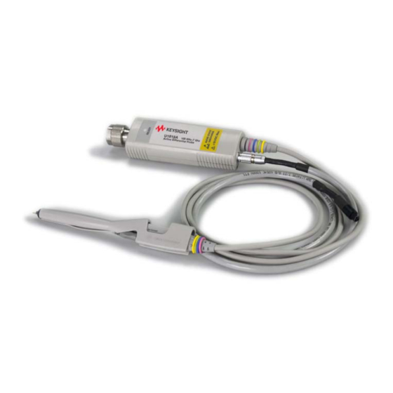
Introduction Product Overview The Keysight U1818A/B active differential probes provides high differential input impedance from 100kHz to 7 or 12GHz. The new probes are designed to be directly compatible with Keysight’s network, spectrum and signal source analyzers. The U1818A/B probes provide high-frequency probing solution for R&D... -
Page 11: Options
Introduction Options There are two DC power supply cable options available for Keysight U1818A/B. – Option 001 - Power probe bias cable – Option 002 - Banana plug cable Figure 1-2 Power probe bias cable Figure 1-3 Banana plug cable There are five probe head options available for Keysight U1818A/B. -
Page 12: Figure 1-4 E2695A Differential Sma Probe Head For Infiniimax Probe
Introduction Figure 1-4 E2695A differential SMA probe head for InfiniiMax probe Figure 1-5 N5380A InfiniiMax II 12GHz differential SMA adapter Keysight U1818A/B Operating and Service Manual... -
Page 13: Figure 1-6 N5381A 12Ghz Infiniimax Differential Solder-In Probe Head And Accessories
Introduction Figure 1-6 N5381A 12GHz InfiniiMax differential solder-in probe head and accessories Figure 1-7 N5382A InfiniiMax II 12GHz differential browser Keysight U1818A/B Operating and Service Manual... -
Page 14: Figure 1-8 N5425B 12Ghz Infiniimax Zif Solder-In Probe Head
Introduction Figure 1-8 N5425B 12GHz InfiniiMax ZIF solder-in probe head Figure 1-9 N5426A 12GHz InfiniiMax ZIF Tip - kit of 10 Keysight U1818A/B Operating and Service Manual... - Page 15 Keysight U1818A/B Active Differential Probe Operating and Service Manual Service and Maintenance Operating Instructions Other Probe Heads Other Available Accessories Handling Guide Maintenance Service Instructions This chapter provides you the operating instructions, service information and handling guide.
-
Page 16: Service And Maintenance
Banana plug cable Connect the banana plug cable to power supply with below configuration: – Red - > +15V – Black - > - 12.6V – Green - > Ground Keysight U1818A/B Operating and Service Manual... -
Page 17: Other Probe Heads
Service and Maintenance Other Probe Heads Besides standard probe head options, below are some other probe heads that can be used with U1818A/B (with limitations). Figure 2-1 N5451A differential long wire ZIF tip Figure 2-2 E2677A 12 GHz differential solder-in probe head... -
Page 18: Figure 2-3 E2678A Single-Ended/Differential Socketed Probe Head
Service and Maintenance Figure 2-3 E2678A single-ended/differential socketed probe head Figure 2-4 E2675A differential browser kit Keysight U1818A/B Operating and Service Manual... -
Page 19: Figure 2-5 E2679A Single-Ended Solder Probe Head
Service and Maintenance Figure 2-5 E2679A single-ended solder probe head Figure 2-6 E2676A single-ended browser probe head Keysight U1818A/B Operating and Service Manual... -
Page 20: Figure 2-7 E2669A Differential Connectivity Kit
Service and Maintenance Figure 2-7 E2669A differential connectivity kit Figure 2-8 E2668A single-ended connectivity kit Keysight U1818A/B Operating and Service Manual... -
Page 21: Other Available Accessories
Other Available Accessories There are more accessories that you can get from Keysight to work with U1818A/B. Figure 2-9 N2880A in-line attenuator kit Figure 2-10 N2881A DC blocking capacitor Figure 2-11 11852B minimum loss attenuator pad Keysight U1818A/B Operating and Service Manual... -
Page 22: Figure 2-12 N2784A 1-Arm Probe Positioner
Service and Maintenance Figure 2-12 N2784A 1-arm probe positioner Figure 2-13 N2785A 2-arm probe positioner Keysight U1818A/B Operating and Service Manual... -
Page 23: Figure 2-14 N2787A 3D Probe Positioner
Service and Maintenance Figure 2-14 N2787A 3D probe positioner Figure 2-15 N5450A InfiniiMax extreme temperature cable extension Figure 2-16 E3620A 50W dual output power supply, two 25V, 1A Keysight U1818A/B Operating and Service Manual... -
Page 24: Handling Guide
This can damage the pins in the amplifier or the probe head itself. Figure 2-18 is an example of an improper way to disconnect the probe head. Keysight U1818A/B Operating and Service Manual... -
Page 25: Figure 2-18 An Improper Way To Disconnect A Probe Head From An
If you connect and disconnect probe heads using the appropriate method, these pins should not bend. Always remember to apply enough force to pull the probe head straight out or push it straight in. Do not wiggle, twist, or bend it in any way. Keysight U1818A/B Operating and Service Manual... -
Page 26: Handling The Probe Cable
This will allow the cable rotations to lie flat against each other and will eliminate the net twisting of the cable in the end. Note that the radius of the coil must be fairly large so it does not induce kinking or bending. Keysight U1818A/B Operating and Service Manual... -
Page 27: Handling The Probe Amplifier
These probes are sensitive ESD devices so standard precautions needto be CAUTION used to not ruin the probe from the build-up of static charges. Keysight U1818A/B Operating and Service Manual... -
Page 28: Handling The Differential Browsers With Ergonomic Handle
Figure 2-22 shows how to remove the browser from the ergonomic handle. Figure 2-21 Steps to mount the browser in the ergonomic handle Keysight U1818A/B Operating and Service Manual... -
Page 29: Handling Sma Probe Heads
Steps to remove the browser from the ergonomic handle Handling SMA probe heads The U1818A/B probe amplifier can become damaged when used with the N5380A or E2695A SMA probe heads. Use the Keysight N5380-64701 SMA Head Support to prevent damage. Make sure to plug the probe amplifier into the SMA head before installing the SMA Head Support and do not attempt to plug or unplug the SMA head from the probe amplifier while it is in the SMA head support housing. -
Page 30: Temperature Rating
Attaching the SMA head support Temperature rating U1818A/B probe amplifier have a specified operating temperature range of 0°C to +50°C. However, the probe heads can be operated over a much larger range of temperatures. If you need to make measurements at temperatures outside the range of the amplifier, the N5450A Extreme Temperatures Cable Extension Kit is your solution. -
Page 31: Securing Probe Heads And Amplifiers To Your Duts
The provided velcro pads can be used to secure your probe amplifier casing to the board. Figure 2-24 Correct securing methods Figure 2-25 Incorrect securing method because glue is placed on the probe head tip Keysight U1818A/B Operating and Service Manual... -
Page 32: Maintenance
If the probe requires cleaning, disconnect it from the instrument and clean it with a soft cloth dampened with a mild soap and water solution. Make sure the probe is completely dry before reconnecting it to the instrument. Keysight U1818A/B Operating and Service Manual... -
Page 33: Service Instructions
The probe amplifiers do not have internal adjustments and should not be opened. Repair The U1818A/B contain no user serviceable parts (with the exception of the probe head). If service or repair is required, contact your nearest Keysight Technologies Service Center. Refer to “Sales and Technical Support”... -
Page 34: Figure 2-26 Holding Tip With Vise
See Figure 2-26. When tightening the vise, use light force to avoid damaging the solder-in CAUTION probe head. Figure 2-26 Holding tip with vise Keysight U1818A/B Operating and Service Manual... - Page 35 7 Cut the wires that protrude on the bottom side of the probe head board even with the solder pad. 8 Place the wires through the hole in the trim gauge with the probe head perpendicular to the trim gauge. Refer to Figure 2-27. Keysight U1818A/B Operating and Service Manual...
-
Page 36: Figure 2-27 Use Trim Gauge To Gauge The Wire
Service and Maintenance Figure 2-27 Use trim gauge to gauge the wire 9 Cut the wires even with the trim gauge on the side opposite of the probe head. Keysight U1818A/B Operating and Service Manual... -
Page 37: Figure 2-28 Cut The Wires Even With The Trim Gauge
Cut the wires even with the trim gauge 10 When replacing wires on the N5382A Browser, bend the wires down at about 30 degree angle. Figure 2-29 N5382A wire bend down at about 30 degree Keysight U1818A/B Operating and Service Manual... -
Page 38: Procedures And Soldering Tips For Using N5425A Infiniimax Zif Probe Heads
Figure 2-30. Note that lever on the ZIF tip is shown in the open position (pointed up) which allows the insertion of the probe head contacts into the ZIF tip with zero insertion force. Keysight U1818A/B Operating and Service Manual... -
Page 39: Figure 2-30 Zif Tip (Open Position) And Zif Probe Head
Service and Maintenance Figure 2-30 ZIF tip (open position) and ZIF probe head Figure 2-31 ZIF tip (closed position) with ZIF probe head inserted Keysight U1818A/B Operating and Service Manual... - Page 40 ZIF tip PC board could flow and the lead would come off destroying the ZIF tip. Only the first third of the lead or so needs to be soldered to the target point. Keysight U1818A/B Operating and Service Manual...
- Page 41 IC package for example ZIF tip installation 1 Add some solder to the target points in the DUT. Figure 2-33 shows extra solder added to the pads for the first two pins on an IC package. Keysight U1818A/B Operating and Service Manual...
-
Page 42: Figure 2-33 Solder Added To Target Points
Solder added to target points 2 Use flux pen to add flux to the target points. Also, flux the tip of the lead on the ZIF tip at this time. Figure 2-34 Fluxing of the target points Keysight U1818A/B Operating and Service Manual... -
Page 43: Figure 2-35 Small Amount Of Solder Added To Zif Tip Of Soldering Iron
There should not be so much solder that the big solder ball is formed that could cause a solder bridge or overheat the leads on the ZIF tip. This is shown in Figure 2-36. Keysight U1818A/B Operating and Service Manual... -
Page 44: Figure 2-36 Zif Tip Positioned And Soldered In Place
Figure 2-37 shows a toothpick releasing the latch on the ZIF connector and Figure 2-38 shows the ZIF tip left behind in the DUT with the latch open, ready for future connections. Keysight U1818A/B Operating and Service Manual... -
Page 45: Figure 2-37 Using Non-Conductive Tool To Open The Zif Connector
Service and Maintenance Figure 2-37 Using non-conductive tool to open the ZIF connector Figure 2-38 ZIF Tip left behind in DUT with ZIF latch open Keysight U1818A/B Operating and Service Manual... -
Page 46: Figure 2-39 Use Non-Conductive Tool To Close The Latch
PC board at the tip while the latch is being closed. If the circuit is live and there is concern about shorting anything out, use plastic or non-conductive tweezers. See Figure 2-39. Figure 2-39 Use non-conductive tool to close the latch Keysight U1818A/B Operating and Service Manual... - Page 47 This information is subject to change without notice. Always refer to the English version at the Keysight website for the latest revision. © Keysight Technologies 2013 - 2019 Edition 5, April 17, 2019 Printed in Malaysia *U1818-90001* U1818-90001...
Need help?
Do you have a question about the U1818A and is the answer not in the manual?
Questions and answers