Table of Contents
Advertisement
Quick Links
Advertisement
Table of Contents

Related Manuals for Milesight MS-C2942-B


Summary of Contents for Milesight MS-C2942-B
-
Page 1: User Manual
User Manual PTZ Network Camera User Manual V1.05... -
Page 2: Copyright Statement
Milesight Technology Co., Ltd (Hereinafter referred to as Milesight). Milesight reserves the right to change this manual and the specifications without prior notice. The latest specifications and user documentation for all Milesight products are available on our official website www.milesight.com... -
Page 3: Safety Instruction
Safety Instruction These instructions are intended to ensure that user can use the product correctly to avoid danger or property loss. The precaution measures are divided into “Warnings” and “Cautions” Warnings: Serious injury or death may be caused if any of these warnings is neglected. Cautions: Injury or equipment damage may be caused if any of these cautions are neglected. - Page 4 EU Conformity Statement 2012/19/EU (WEEE directive): Products marked with this symbol cannot be disposed of as unsorted municipal waste in the European Union. For proper recycling, return this product to your local supplier upon the purchase of equivalent new equipment, or dispose of it at designated collection points.
-
Page 5: Table Of Contents
3.1.2 Assign An IP Address via Browser ................11 3.2 Accessing from the Web Browser ..................14 3.2.1 Access over IE Browser ....................14 3.3 Accessing from Milesight VMS (Video Management Software) ........... 16 Chapter IV System Operation Guide....................17 4.1 Live Video..........................17 4.1.1 Operations on Live View Page.................. -
Page 6: Chapter I Product Description
Chapter I Product Description 1.1 Product Overview Milesight provides a consistent range of cost-effective and reliable network cameras to fully meet your requirements. Based on embedded Linux operating system, Milesight network cameras could be easily accessed and managed either locally or remotely with great reliability. -
Page 7: Hardware Overview
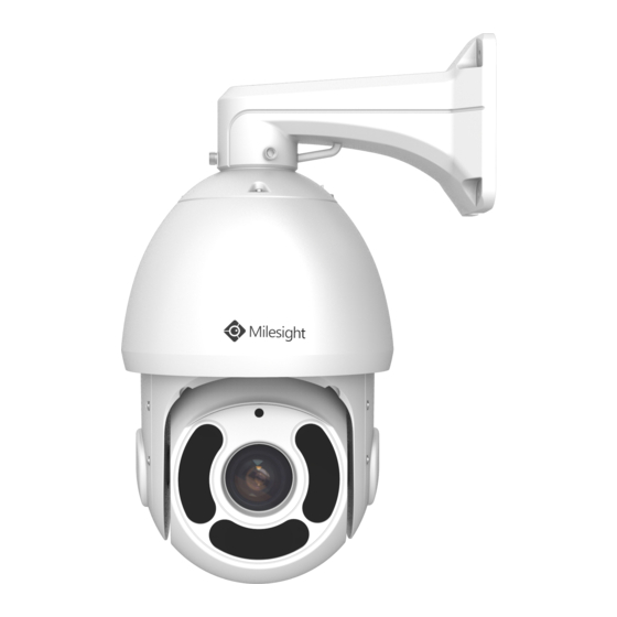
1.3 Hardware Overview Speed Dome Network Camera Figure 1-3-1 Speed Dome Network Camera Note: 1) DC 12V and AC 24V are available for power supply. 2) Built-in SD card slot can be seen after removing the 4 screws and open the front panel. File Format:MS-QR-JS-04 Rev1.0 Durability Date:1Year... - Page 8 Mini PTZ Bullet Network Camera Screw-in Vent Figure 1-3-2 Mini PTZ Bullet Network Camera Note: 1) Only DC 12V is available for power supply. File Format:MS-QR-JS-04 Rev1.0 Durability Date:1Year...
-
Page 9: System Requirements
1.4 System Requirements Operating System: Windows XP/Vista/7/8/10/Server 2000/Server 2008 CPU: 1.66GHz or higher RAM: 1G or higher Graphic memory: 128MB or more Internet protocol: TCP/IP (IPv4/IPv6) Web Browsers: Internet Explorer 8.0 and above version, Mozilla Firefox, Google Chrome and Safari. File Format:MS-QR-JS-04 Rev1.0 Durability Date:1Year... -
Page 10: Chapter Ii Network Connection
Chapter II Network Connection 2.1 Setting the Camera over the LAN Connecting the camera to a switch or a router is the most common connection method. The camera must be assigned an IP address that is compatible with its LAN. 2.1.1 Connect the Camera to the PC Directly In this method, only when the computer connected to a camera, it will be able to view the camera. - Page 11 assistance with port forwarding; Step4: Apply a domain name from a domain name provider; Step5: Configure the DDNS settings in the setting interface of the router; Step6: Visit the camera via the domain name. Figure 2-2 Connect the network camera via a router using dynamic IP File Format:MS-QR-JS-04 Rev1.0 Durability Date:1Year...
-
Page 12: Chapter Iii Accessing The Network Camera
3.1 Assigning An IP Address The Network Camera must be assigned an IP address to be accessible. The default IP address of Milesight Network Camera is 192.168.5.190. The default user name is “admin”, and password is “ms1234”. You can either change the IP address of the camera via Smart Tools or browser. Please connect the camera in the same LAN of your computer. - Page 13 Step3: Select a camera or multiple cameras according to the MAC addresses; Figure 3-1-2 Select single camera Figure 3-1-3 Select multiple cameras File Format:MS-QR-JS-04 Rev1.0 Durability Date:1Year...
- Page 14 Step4: Type the User Name and Password (admin/ms1234 for default, please change your password for your device security); Figure 3-1-4 Type the User Name and Password Step5: Change the IP address or other network values, and then click “Modify” button; Figure 3-1-5 Modify File Format:MS-QR-JS-04 Rev1.0 Durability Date:1Year...
-
Page 15: Assign An Ip Address Via Browser
Step6: Change the IP address successfully; Figure 3-1-6 Change IP address successfully Step7: By double clicking the selected camera or the browser of interested camera, you can access the camera via web browser directly. The Internet Explorer window will pop up. Figure 3-1-7 Login interface More usage of Smart Tools, please refer to the Smart Tools User Manual. - Page 16 Click “Advanced”, and then click “IP settings” “IP address” “Add” (See Figure 3-1-9). In the pop-up window, enter an IP address that in the same segment with Milesight network camera ( e.g. 192.168.5.61, but please note that this IP address shall not conflict with the IP address on the existing network);...
- Page 17 Step2: Start the browser. In the address bar, enter the default IP address of the camera: http://192.168.5.190; Step3: Enter the user name and password when the LOGIN page appears; Default user name: admin Default password: ms1234 Figure 3-1-10 Login Step4: After login, please select “Configuration” “Basic Settings” “Network” “TCP/IP”. The Network Settings page appears (Shown as below Figure);...
-
Page 18: Accessing From The Web Browser
Figure 3-2-2. Please click “Finish” and refresh the browser, then you will see the video. Figure 3-2-2 Finish installation If IE9 or higher version browser is used, it is suggested that the Milesight camera web link should be added as a trusted site. See the instructions as follows: Step1: Start the IE9 or higher version browser, and select “Tools”... - Page 19 Figure 3-2-3 To add the permission Step2: Select “Security” to “Trusted”; Figure 3-2-4 To trust the control Step3: Enter the IP address of the camera in the blank and click “Add”; Figure 3-2-5 Add the website to the zone File Format:MS-QR-JS-04 Rev1.0 Durability Date:1Year...
-
Page 20: Accessing From Milesight Vms (Video Management Software)
The interface of Milesight VMS is very easy to use, intuitive, with easy access to the most common activities, such as viewing live video, searching through recordings and exporting videos and snapshots. -
Page 21: Chapter Iv System Operation Guide
Chapter IV System Operation Guide 4.1 Live Video After logging in the network camera web GUI successfully, you are allowed to view live video as follows. Figure 4-1-1 Live view interface 4.1.1 Operations on Live View Page Table 4-1-1 Description of the buttons Parameter Description Navigation key is used to control the direction. - Page 22 Click to focus near and far of the lens. Click to adjust the size of Iris. Auxiliary Focus and Lens Initialization Brightness: Drag to adjust brightness of the image. Contrast: Drag to enhance the differences in color and light between parts of an image. Saturation: Drag to adjust color saturation of the image.
-
Page 23: Positioning
Click to display images at a real size. Real size Click to display images at full-screen. Full Screen When recording, the icon will turn red. Recording When an alarm causes recording, the icon will turn red. Alarm Click to start/stop Live View. Click to capture the current image and save to the configured path. -
Page 24: Setting / Calling A Preset / Patrol / Pattern
Hold down the left mouse button and drag the mouse to the lower left or upper left on the Live View, you can see a red rectangle. The corresponding position will be moved to the center of the Live View and Zoom out. ... - Page 25 Figure 4-1-3 calling a Preset Note: The following presets are predefined with special commands. You can only call them but can’t configure them. For example, preset 035 is the “Self Check”. If you call the preset number 035, the PTZ camera will start self check function at once. Table 4-1-2 Special Presets Special Special...
- Page 26 configuring the patrol, you should make sure that the presets you want to add to the patrol have been defined. Setting a patrol: Step1: In the PTZ control panel, click to enter the patrol settings interface; Step2: Select a patrol number, the setting icon will appear , click it;...
- Page 27 Note: The four buttons behind the Patrol list means: Play, Stop, Set and Delete. Setting / Calling a pattern A pattern is a memorized series of pan, tilt, zoom and preset functions. It can be called on the pattern settings interface. There are up to 4 patterns can be set. Setting a pattern: Step1: In the PTZ control panel, click to enter the pattern settings interface;...
-
Page 28: Playback
4.2 Playback This section explains how to view remotely the recorded video files stored in SD cards. Step1: Click and then click on the menu bar to enter playback interface; Figure 4-2-1 Playback interface Step2: Click the date button, choose the date when date window pops up; Figure 4-2-2 Search Video Note: The date with deep red means there is recorded file in this day;... -
Page 29: Basic Settings
Table 4-2-1 Description of the buttons Button Operation Play Pause Stop Slow Forward Fast Forward Audio On/Off Search Go To Time Narrow/Expand Start/Stop Recording Snapshot Digital Zoom On/Off Full Screen Note: Drag the progress bar with the mouse to locate the exact playback point. You can also input the time and click to locate the playback point in the Set Playback Time filed. - Page 30 Primary Stream Settings Figure 4-3-1 Primary Stream Settings Secondary Stream Settings Figure 4-3-2 Secondary Stream Settings Tertiary Stream Settings Figure 4-3-3 Tertiary Stream Settings Table 4-3-1 Description of the buttons Parameters Function Introduction Video Codec H.265/H.264/MJPEG are available. Options include 4M(2592*1520) (only for 4MP Mini PTZ Bullet), 3M(2048*1536), Frame Size 1080P(1920*1080), 1.3M(1280*960), 720P(1280*720), D1 (704*576).
-
Page 31: Image
For Secondary Stream, it includes 704*576, 640*480, 640*360, 352*288, 320*240, 320*192, 320*176. For Tertiary Stream, it include 1920*1080, 1280*720, 704*576, 640*480, 640*360, 320*240, 320*192, 320*176. Maximum Frame Rate It means maximum refresh frame rate of per second. Set the bitrate to 32~16384 Kbps. The higher value corresponds to the Bit Rate higher video quality, and the higher bandwidth is required as well. - Page 32 Table 4-3-2 Description of the buttons Parameters Function Introduction Power Line Frequency 60HZ flicker for NTSC mode and 50HZ flicker for PAL mode There are several parameters such as Exposure Level, Maximum Exposure Time and IR-CUT Interval, etc, associated with this mode. Night Mode: Shown in live view based on Night Mode settings Day Mode: Shown in live view based on Day Mode settings Day/Night Mode...
- Page 33 Enhancement Figure 4-3-5 Enhancement Settings Table 4-3-3 Description of the buttons Parameters Function Introduction There is an option to turn On/Off the IR LED. Turn smart IR on, and the IR LED Smart IR will change according to the actual illumination. To restore white objects and remove color distortion because of the light of the environment Auto White Balance: This option will automatically enable the White Balance...
- Page 34 Auto mode/Customize mode. If you choose customize mode, the camera Exposure Mode adjusts the brightness according to the value as set. The higher the value, the (BLC) brighter the image. This function enables the capture and display of both bright and dark areas in the same frame.
- Page 35 Day/Night Mode Figure 4-3-8 Day/Night Mode Settings Table 4-3-4 Description of the buttons Parameters Function Introduction Exposure Level Level 0~10 are available to meet your need. Maximum Exposure Set the maximum exposure time to 1/5~1/100000. Time IR-CUT Interval Keep the mode from switching. IR-CUT Choose to turn on or turn off under this mode.
-
Page 36: Audio
OSD(On Screen Display) Figure 4-3-9 OSD Settings Table 4-3-5 Description of the buttons Parameters Function Introduction Show Video Title Check the checkbox to show video title Video Title OSD content customized Text Position OSD display position on the image Show Timestamp Check the checkbox to display date on the image Date Position Date display position on the image... - Page 37 Figure 4-3-10 Audio Settings Table 4-3-6 Description of the buttons Parameters Function Introduction Enable Audio Check on the checkbox to enable audio feature. Denoise: Set it as On/Off. When you set the function on, the noise detected can be filtered. Encoding: G711-ULaw, G711-ALaw and AAC LC are available;...
-
Page 38: Network
4.3.4 Network TCP/IP Figure 4-3-12 TCP/IP Settings Table 4-3-7 Description of the buttons Parameters Function Introduction Get IPv4 Address Get an IP address from the DHCP server automatically. Automatically IPv4 Address: It is used to identify a network camera on the network; IPv4 Subnet Mask: It is used for identifying the subnet where the network camera is located;... - Page 39 HTTP Figure 4-3-13 HTTP Settings Table 4-3-8 Description of the buttons Parameters Function Introduction HTTP Enable Start or stop using HTTP. HTTP Port Web GUI login port, the default is 80, the same with ONVIF port. HTTPS Enable Start or stop using HTTPS. HTTPS Port Web GUI login port via HTTPS.
- Page 40 Tertiary Stream http://username:password@IP:port/mjpegthird.cgi RTSP Figure 4-3-14 RTSP Settings Table 4-3-8 Description of the buttons Parameters Function Introduction RTSP Port The port of RTSP, the default is 554. Playback Port The port of playback, the default is 555. There are Better Compatibility and Better Performance two options. If your RTP Packet camera’s image mess up, please switch this option.
-
Page 41: Date&Time
3) A reboot is required for the settings to take effect. 4) The tertiary stream is only equipped on camera whose model with “-A” or “-B”. 4.3.5 Date&Time Figure 4-3-15 Date&Time Settings Current System Time Current date&time of the system Set the System Time Table 4-3-9 Description of the buttons Parameters... -
Page 42: Advanced Settings
By using Milesight ROI technology, more than 50% of bit rate can be saved. Therefore less bandwidth are demanded and the storage usage are reduced. So according to that, you can set a small bit rate for high resolution. -
Page 43: Network
Figure 4-4-2 ROI Settings Table 4-4-2 Description of the buttons Parameters Function Introduction Enable Check the checkbox to enable the ROI function. Clear All Clear all areas you drew before. Video Stream Choose the Video Stream. Note: ROI will be more obvious in the case of low bit rate. 4.4.2 Network There are more several modules in Advanced Settings than those in Basic Settings. - Page 44 IP address and update your domain information dynamically. You need to register an account from a provider. . Figure 4-4-4 DDNS Settings You can choose “ddns.milesight.com” as provider for DDNS. After enabling, you can access the device via the URL “http://ddns.milesight.com/MAC address” . Table 4-4-4 Description of the buttons...
- Page 45 Host name DDNS name enabled in the account Note: 1)Please do the Port Forwarding of HTTP Port and RTSP Port before you use Milesight DDNS. 2)Make sure that the internal and the external port number of RTSP are the same. SMTP Alarm video files can be sent to specific mail account through SMTP server.
- Page 46 Alarm video files can be sent to specific FTP server. You must configure the FTP settings correctly before using it. Figure 4-4-6 FTP Settings Table 4-4-6 Description of the buttons Parameters Function Introduction Server Address FTP server address Server Port The port of the FTP server.
- Page 47 PPPoE This camera supports the PPPoE auto dial-up function. The camera gets a public IP address by ADSL dial-up after the camera is connected to a modem. You need to configure the PPPoE parameters of the network camera. Figure 4-4-8 PPPoE Settings Note: 1) The obtained IP address is dynamically assigned via PPPoE, so the IP address always changes after rebooting the camera.
-
Page 48: Alarm
Table 4-4-7 Description of the buttons Parameters Function Introduction The version of SNMP, please select the version of your SNMP software. SNMP v1: Provide no security; SNMP v1/2/3 SNMP v2: Require password for access; SNMP v3: Provide encryption and the HTTPS protocol must be enabled. Write Community Input the name of Write Community. - Page 49 Figure 4-4-10 Motion Region Settings Table 4-4-8 Description of the buttons Parameters Function Introduction Enable Motion Check the checkbox to enable Motion Detection function. Detection Select All Click the button, and the motion in the area will be detected. Clear All Click the button, and the area drawn before will be removed.
- Page 50 Step4: Set alarm action; Figure 4-4-12 Alarm Action Table 4-4-9 Description of the buttons Parameters Function Introduction Save Into SD Card Save alarm recording files into SD Card. Save Into NAS Save alarm recording files into NAS. Upload Via FTP Upload the recording files via FTP.
- Page 51 NOTE: The HTTP notification function is just one way for camera to send messages to VMS Software. And it's the VMS that defines what the messages mean and decides what to do after receiving this kind of messages. So, we can use the HTTP Notification function of our cameras only if the VMS supports this kind of message format.
- Page 52 Step4: If successful, you can see the device icon turn yellow in the Surveillance when the camera is under Motion Detection Alarm; So, it's the VMS Software which decides whether we can use this function successfully. Step5: Set alarm settings. Figure 4-4-13 Alarm Settings Table 4-4-10 Description of the buttons Parameters...
-
Page 53: Audio Alarm
The duration of flash. White LED Flash Time Twinkle from 1 second to 10 seconds; Always from 1second to 60 seconds. PTZ Motion Recovery The duration of one alarm. It must be longer than flash time. Time Audio Alarm Enable the Audio before using Audio Alarm function. Figure 4-4-14 Schedule Settings Figure 4-4-15 Alarm Settings Please refer to table 4-4-8 and 4-4-9 to get the meaning of items. -
Page 54: Storage
Figure 4-4-16 Region Detection Settings Step1: Set region and sensitivity; Step2: Set region detection schedule; Step3: Set alarm action; Step4: Set alarm settings. Figure 4-4-17 Alarm Settings Please refer to table 4-4-8 and 4-4-9 to get the meaning of items. 4.4.4 Storage Before you start: To configure record settings, please make sure that you have the network storage device within the... -
Page 55: Record Schedule
You can check “Enable Recycle storage”, then it will delete the files when the free disk space reach a certain value. Choose the storage mode according to your needs. SD Card Figure 4-4-18 SD Card Table 4-4-11 Description of the buttons Parameters Function Introduction Format... - Page 56 Table 4-4-12 Description of the buttons Parameters Function Introduction Record Storage Type SD or NAS are available. File Sizes: Set record file size, (10-256)M Record Frame Type: All/Key Record Settings (All: Record all the frame Key: Only record I-frame) Schedule Settings Click the Edit button to edit record schedule.
- Page 57 SD card video files are arranged by date. Each day files will be displayed under the corresponding date, from which you can copy and delete files etc. You can visit the files in SD card by ftp, for example, ftp://username:password@192.168.5.190(User name and password are the same as the camera account and the IP followed is the IP of your device.).
-
Page 58: Security
Table 4-4-14 Description of the buttons Parameters Function Introduction Enable Time Snapshot: Check the checkbox to enable the Timing Snapshot function; Interval: Set the snapshots interval, input the number and choose the unit(millisecond, second, minute, hour, day); Save Into SD Card: Save the snapshots into SD card, and choose the file name to add time suffix or overwrite the base file name;... -
Page 59: Access List
Table 4-4-15 Description of the buttons Parameters Function Introduction Allow anonymous viewing: Check the checkbox to enable visit from whom Manage Privilege doesn’t have account of the device. User Name: Input user name for creating an account; User Password: Input password for the account; Account Management Confirm User Password: Confirm the password;... -
Page 60: Sip
Internet Protocol(IP) networks. This page allows user to configure SIP related parameters. Milesight cameras can be configured as SIP endpoint to call out when alarm triggered; or allow permitted number to call in to check the video if the video IP phone is used. - Page 61 SIP Settings Figure 4-4-27 SIP Settings Table 4-4-17 Description of the buttons Parameters Function Introduction Unregistered/ SIP registration status. Display “Unregistered” or “Registered” Registered Enable Start or stop using SIP Choose to use Enable mode or Disable mode. Enable mode means to use SIP with Register Mode register account.
-
Page 62: Ptz
Alarm Phone List Figure 4-4-28 Alarm Phone List Table 4-4-18 Description of the buttons Parameters Function Introduction Phone Number(Call by phone number) & Direct IP Call(Check to accept peer to Phone Type peer IP call). Phone Number/ Call by phone number or IP address. IP Address Remark Name Display name. - Page 63 Scheduled Tasks. Basic Figure 4-4-30 Basic Settings of PTZ Table 4-4-20 Description of the buttons Parameters Function Introduction Before showing the preset Live View, it will not show the moving path if you Preset Freezing enable Preset Freezing. It can also reduce the use of bandwidth in a digital network system Preset Speed It will decide the speed of calling presets.
- Page 64 Auto Home Figure 4-4-31 Auto Home Auto Home allows the PTZ camera to return to a predefined Home Position automatically after a period of latency time. Check the checkbox to enable the Auto Home mode. Table 4-4-21 Description of the buttons Parameters Function Introduction Latency Time...
- Page 65 Figure 4-4-33 PTZ Limit Step1: Check the checkbox to enable the PTZ Limit function. Step2: Choose the limit mode as Manual limit or scanning limit. Manual limit: When Manual limit stops are set, you can operate the PTZ control panel manually only in the limited surveillance area.
-
Page 66: Logs
Scheduled Tasks You can configure the PTZ camera to perform a certain action automatically in a user-defined time period. Step1: Enter the Scheduled Task Settings interface: Figure 4-4-35 Scheduled Task interface Step2: Check the checkbox of Enable Scheduled Task. Step3: Set the schedule and task details. Step4: Set the Task Recovery Time(from 5 to 720 seconds). -
Page 67: System
Figure 4-4-36 Logs Table 4-4-23 Description of the buttons Parameters Function Introduction There are five main log types: All Type, Event, Operation, Information, Main Type Exception. On the premise that main type has been selected, select the sub type to narrow Sub Type the range of logs. - Page 68 System Up Time The elapsed time since the last restarted of the device QR Code Directly add the device on Milesight APP by scanning it. Note: 1) The QR code will appear after the P2P of IP camera is activated.
-
Page 69: Maintenance
4.6 Maintenance The software can be upgraded by the following steps: Step1: Browse and select the upgrading file; Step2: Click the “upgrade” button after it prompts upload file successfully. After the system reboots successfully, the update is done. Note: 1) Do not disconnect the power of the device during the update. The device will be restarted to complete the upgrading. -
Page 70: Chapter V Services
Chapter V Services Milesight Technology Co., Ltd provides customers with timely and comprehensive technical support services. End-users can contact your local dealer to obtain technical support. Distributors and resellers can contact directly with Milesight for technical support. Technical Support Mailbox: support@milesight.com Web: http://www.milesight.com...
Need help?
Do you have a question about the MS-C2942-B and is the answer not in the manual?
Questions and answers