
Related Manuals for SolarMax SHT Series


Summary of Contents for SolarMax SHT Series
- Page 1 SolarMax SHT-series 17SHT / 20SHT / 22SHT / 25SHT / 28SHT / 30SHT Instruction Manual...
- Page 2 SolarMax Produktions GmbH Zur Schönhalde 10 D-89352 Ellzee E-Mail: info@solarmax.com © SolarMax Produktions GmbH 2020...
-
Page 3: Table Of Contents
SolarMax Service Center ........ -
Page 5: Notes On The Manual
The plant operator must ensure that this instruction manual is available to the relevant per- sons at all times. If this original document is lost, an up-to-date version of this instruction manual can be downloaded from our website at any time (www.solarmax.com). 1�4... -
Page 6: Safety
Any other use is contrary to the intended use. Inverters of the SHT series may only be used in combination with PV modules which comply with the IEC 61730 standard. Inverters of the SHT series may only be connected to Class II PV generators. -
Page 7: Symbols
Do not open the inverter and do not make modifications or holes of any Removing type. In case these instructions are not observed, then SolarMax does not this label voids the assume any liabilities for damages to persons or properties. -
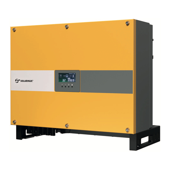
Page 8: Description
Fig. 1: Label of SolarMax 30SHT 3�2 Function The SolarMax SHT Series inverters have the following characteristics that provide high effi- ciency and high reliability: Wide input DC range, allowing maximum flexibility in the configuration of the PV ■... -
Page 9: Front Panel
Additionally, in the SHT Series inverters integrate the following protection devices: Internal overvoltage ■ DC insulation monitoring ■ Ground fault protection ■ Grid monitoring ■ Current leakage protection ■ DC current monitoring protection ■ DC disconnector integrated ■ Reverse DC polarity protection ■... - Page 10 Warning/Alarm Alarm Grid Comm� Warning Code indicator indicator indicator indicator Normal status Startup phase Communication active PV normal Grid over voltage Grid under voltage No grid ...
-
Page 11: Display
3�3�2 Display Warning Date/Time Status Output Meter Fig. 3: Display of SHT inverters Display Description This symbol is displayed when the SHT is transmitting data via WLAN. If this communication interface is not used, the character is no longer displayed after about 10 s. This character is displayed when the SHT is transmitting data via the RS485 interface. -
Page 12: Connections In The Lower Part
3�4 Connections in the lower part Fig. 4: Connections in the lower part Position Description PV Strings terminal DC Isolation switch Communication interface RS485 interface AC output terminal Fan (25SHT, 28SHT, 30SHT) Vent valve External PE connection... -
Page 13: Installation
Installation CAUTION! The inverter is a heavy device! To prevent personal injury or device damage, arange two people to move the ■ inverter and handle with care. 4�1 Package contents When the inverter is delivered check and report any damage on the box that may affect its contents. -
Page 14: Selecting The Installation Location
4�2 Selecting the installation location DANGER! Fatal fire or explosion hazard! The inverter is an electrical device with heat generation and the possibility of sparking. Install the inverter in an environment that is free of flammable gases and fluids ■ Never install the inverter near combustible materials. -
Page 15: Mounting The Inverter
4�3 Mounting the inverter NOTE The SHT series inverters should be mounted on a mounting system or substruc- ture. A mounting system is not included. All commercially available mounting sys- tems are suitable which guarantee permissible mounting. The inverter is attached to the wall or to a mounting system using a mounting plate. The mounting plate and the mounting material are included in the scope of delivery. - Page 16 2. Drill the holes. Insert the dowels, position the bracket and insert the screws to lock it. Alternatively, you can fix the supplied mounting plate of the inverter to a mounting system with the corresponding screws. 3. Mount the inverter on the monting bracket and tighten the inverter with rear panel using screws as shown in the following figure: 4.
-
Page 17: Electrical Connection
5�2�1 Integrated RCD and RCM The SHT Series inverters are equipped with integrated RCD (Residual Current Device) and RCM (Residual Current Monitor) according to VDE 0126-1-1. The sensor measures the residual current and compares it to the pre-set value, disconnecting automatically the inverter from the AC grid by means of the integrated RCD in case the value exceeds it. - Page 18 ATTENTION! Install a model B leakage current protection switch with no less than 600 mA current. Do not share neutral wire when B leakage current protection switch is installed or else a power grid trip may occur. AC output cables requirements For AC power cables outdoor multi copper-cores cables are recommended.
- Page 19 Heat shrink tubing Fig. 11: Connecting the OT terminals to the AC cable 4. Loosen the four screws of the AC cover on the inverter and remove the cover. 5. Push the AC cable through the opening in the cable cover from behind. The cable must be pulled through so that the conductors can be connected to the termination strip of the inverter.
- Page 20 Fig. 13: Tightening the wiring board 8. Connect the external Protective Earth cable. Secure the cable tighten the screw. Fig. 14: Connecting the external Protective Earth cable CAUTION! The external Protective Earth connection cannot substitute the one present in the AC connector used to connect the inverter to the grid. Make sure that both cables are present and connected, otherwise warranty may be void in case of failure of the electrical connections.
-
Page 21: Connecting The Inverter To The Pv Generator
5�2�3 Connecting the inverter to the PV generator DANGER! Fatal electric shock hazard! In daylight the PV generator supplies the inverter with a dangerously high DC voltage. The PV generator voltages are very high. NEVER plug or unplug the DC con- ■... - Page 22 17/20/22 SHT 25/28/30 SHT Fig. 15: Route connection for the installation of PV strings Number of Number of input route Inverter type cable pairs All types PV1 and PV4 All types PV1, PV2 and PV4 All types PV1, PV2 and PV4, PV5 All types PV1, PV2, PV3, PV4 and PV5 Only for 25SHT, 28SHT, 30SHT...
- Page 23 Insulation layer Locking nut Fig. 17: Negative pole male connector DANGER! Fatal electric shock hazard! In daylight the PV generator supplies the inverter with a dangerously high DC voltage. The PV generator voltages are very high. NEVER plug or unplug the DC ■...
-
Page 24: Communication Interface
Fig. 20: Locking the cable glands 4. Check with a voltmeter of proper scale that the polarities and the DC voltage values are correct. 800 00 R A N G E M A XM I N R EL H z % Fig. -
Page 25: Commissioning
Commissioning Follow these steps to start up the inverter: 1. Switch ON the DC isolation switch on the lower part of the inverter (see Fig. 2. Switch on the external switch of the AC feed line connecting the inverter to the grid. 3. -
Page 26: Configuration
Configuration 7�1 Installation of MaxLink App The inverter is provided with the basic configuration to operate in the country where it was sold. In case of operation in a different country, or if changes to other parameters are needed, a communication connection to the inverter must be established. In addition, to change settings and to connect the inverter to a Local Area Network (LAN) for monitoring purposes it is necessary to establish such communication link. -
Page 27: Configuration Of The Inverter
Fig. 23: Start menu at the mobile device for inverter configuration The MaxLinkApp establishes the communication with the inverter and downloads the data. Data are displayed on the screen. Inverter is not available at the App MaxLink If connected inverters are not displayed on your mobile device, follow the steps below to display the inverter data on MaxLink: Make sure inverter is switched on ■... - Page 28 Fig. 24: Overview of the MaxLink App 2. Select „Setting“ in the selection menu (see the following figure). Fig. 25: App MaxLink selection menu...
- Page 29 3. Select the button „Change user“ to get the access menu (see the following figure). Fig. 26: App MaxLink Settings 4. Enter the administrator password to change inverter data. Use the password “admin” (see the following figure). 5. Select buttton „Login as Administrator“. Fig.
- Page 30 Fig. 28: App MaxLink inverter settings CAUTION! Inverter settings have to be conform to the specifications of the local energy provider 7. To change the inverter settings select the selection field „Standard Code“. The following selection menu for standard codes will appear.
-
Page 31: Troubleshooting
Troubleshooting measures In case of abnormal behaviour consult the following table to find the cause and try to reset the proper operating conditions. If the proposed measures do not eliminate the fault, contact the SolarMax Service Centre. Problem Maßnahmen zur Stprungsbehebung Check if the DC disconnector has been turned on. -
Page 32: Solarmax Service Center
Serial number S / N ■ Installation location ■ Information on the present failure (status message, etc.) ■ Availability The contact details of the SolarMax Service Center can be found overleaf or at www.solarmax.com. SolarMax Produktions GmbH Zur Schönhalde 10 D-89352 Ellzee... -
Page 33: Technical Data
Technical Data 17SHT 20SHT 22SHT 25SHT 28SHT 30SHT Input MPP voltage range 180 ... 180 ... 180 ... 180 ... 180 ... 180 ... values 950 V 950 V 950 V 950 V 950 V 950 V MPP voltage range 480 ... -
Page 34: 10 Disposal
17SHT 20SHT 22SHT 25SHT 28SHT 30SHT Environ- Protection lass IP65 ment Ambient tem- perature range – 25 … + 60°C (derating over 45°C) (for rated power output) Relative humidity 0 … 100 % (not condensing) Cooling Natural convection Fan assisted Max. -
Page 35: 11 Warranty
1� Basic Guarantee BASIC The services of the Basic Guarantee are only provided free of charge in countries released by SOLARMAX at the time of installation. Please clarify this with your dealer. You will find a current list of these countries in the appendix or on our homepage. - Page 36 The battery is considered defective if its remaining capacity is less than 60% of its nominal capacity. SOLARMAX has the right to optimize the operation of the plant at any time in accordance with the war- ranty, i.e. to qualitatively modify key data and functions for operation and life support and adjust system and battery performance or battery discharge depth to optimise battery life by remote maintenance and control means.
- Page 37 5� Assertion of Guarantee For the assertion of the guarantee the SOLARMAX hotline must be contacted by phone or in written form and their instructions must be followed carefully. You will find the Hotline number for your country on our homepage.
- Page 38 9� Applicable Law, Place of Jurisdiction The Law of the Federal Republic of Germany is applicable, Place of Jurisdiction shall exclusively be Augsburg / Germany, as far as this is permitted by law. Appendix Country List: Austria, Belgium, Bulgaria, Czech Republic, Denmark, France, Germany, Greece, Italy, Liechstenstein, Luxembourg, Netherlands, Poland, Portugal, Slovakia, Slovenia, Spain, Sweden, Switzerland, United Kingdom (Issued 04/2019 –...
- Page 40 SolarMax Service Center You will find all contact information on our website: www.solarmax.com Hotline: + 49 3733 507840 + 41 315281165 + 34 93 2203859 + 44 20 38080346 + 39 0418520076 + 33 820 420 684 + 49 3733 50784 99 Mail hotline@solarmax.com...
Need help?
Do you have a question about the SHT Series and is the answer not in the manual?
Questions and answers