Table of Contents
Advertisement
Quick Links
Advertisement
Table of Contents

Related Manuals for SolarMax SM30HT4


Summary of Contents for SolarMax SM30HT4
- Page 1 SolarMax HT series 30HT4 / 32HT4 Instruction manual...
-
Page 2: Table Of Contents
Contents Notes on this instruction manual � � � � � � � � � � � � � � � � � � � � � � � � � � � � � � � � � � � � 5 Scope. - Page 3 SolarMax Service Center ........
- Page 4 10 Decommissioning� � � � � � � � � � � � � � � � � � � � � � � � � � � � � � � � � � � � � � � � � � � � � � � � 64 10.1 Instructions for inverter replacement .
-
Page 5: Notes On This Instruction Manual
The plant operator must ensure that this instruction manual is available to the relevant persons at all times. If this original document is lost, an up-to-date version of this instruc- tion manual can be downloaded from our website at any time (www.solarmax.com). 1�4... -
Page 6: Safety
2�1 Intended use SolarMax HT series inverters are designed exclusively for the conversion of the direct cur- rent generated by PV modules into alternating current which conforms to the parameters of the public grid. Any other use is contrary to the intended use. -
Page 7: Symbols On Inverter
2�3 Symbols on inverter Symbol Description The DC disconnector is switched off (the contacts are open). The DC disconnector is switched on (the contacts are closed). + − Positive or negative pole of input voltage (DC) Risk of death from high voltages! Only qualified electricians may perform work on the inverter. -
Page 8: Description
Description 3�1 Identification The inverter can be identified on the basis of the information provided on the nameplate (see Section 3.5). 3�2 Functionality Automatic operation Inverter operation is completely automatic and depends on the available output of the PV generator. If there is enough power, the inverter starts mains operation and feeds into the power grid. -
Page 9: Safety Installations
3�3 Safety installations Surge protection The inverter is fitted with surge arresters (varistors) at its input and output. Each MPP tracker (plus and minus connections) is equipped with a surge arrester. On the AC side, each mains phase has a surge arrester (for details on the surge arresters fitted, see Section 11). -
Page 10: Dimensions
3�4 Dimensions Figure 1 Dimensions (with wall mounting bracket) -
Page 11: Views Of The Unit
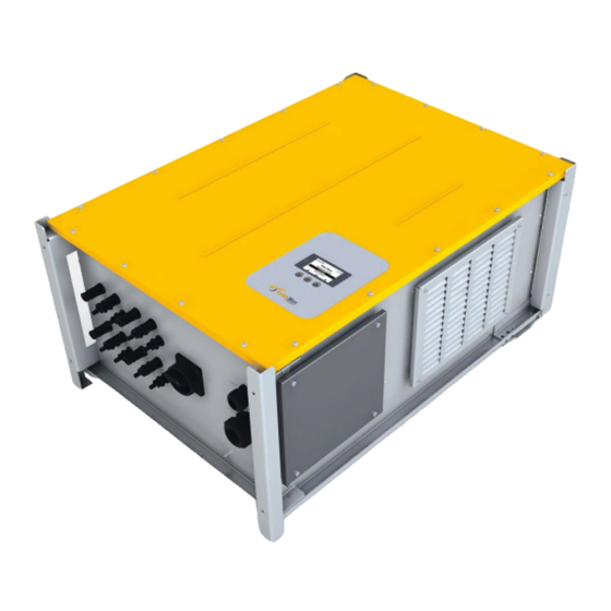
3�5 Views of the unit Figure 2 Views of the unit... - Page 12 No� Description Ventilation inlet Cover Graphics display Type plate Safety brackets Wall mounting bracket Handles (for lifting the inverter by hand) Ventilation outlet "AC mains" cable gland (AC input conductor) "COMM" multiple cable gland (for communication cables) DC disconnector (can be locked with a padlock) DC terminals...
-
Page 13: Block Diagram
3�6 Block diagram AC output AC measurement AC measurement Inverter control Inverter control Booster control Booster control DC input DC input DC input DC input MPP tracker 1 MPP tracker 2 MPP tracker 3 MPP tracker 4 Figure 3 Block diagram... -
Page 14: Installation
Installation 4�1 Transporting and storing inverters Make sure that the ambient conditions during transportation and storage are within the specified limits (for details see Section 11). 4�2 Lifting the inverter The inverter is fitted with handles (Figure 2/Pos. 7), which can be used to lift the inverter from the packaging by hand. -
Page 15: Checking The Delivery For Completeness
4�3 Checking the delivery for completeness Check the contents of the delivered package for completeness and possible damage. In the case of an inadequate delivery, please contact your dealer or the SolarMax Service Center. SolarMax HT-Serie 30HT4 / 32HT4 Gerätedokumentation Figure 4 Content of delivery No�... -
Page 16: Selecting The Installation Location
No� Quantity Description Locking pins (for multiple cable gland) M5 toothed washer (connection of second protective conductor) M5 cable shoe (connection of second protective conductor) M5 circlip (connection of second protective conductor) M5 washer (connection of second protective conductor) M5 nut (connection of second protective conductor) 10 x 50 wall plugs (mounting of inverter) M6 x 18 washers (mounting of inverter) 6 x 60 Torx pan head screws (mounting of inverter) - Page 17 [cm] Figure 5 Minimum installation distances Do not mount the inverter at an angle or on its side: ■ ■ Figure 6 Unacceptable mounting positions Appropriate cooling of the inverter can only take place when the ventilation openings ■ ■ on the sides are kept clear.
-
Page 18: Mounting The Inverter
4�5 Mounting the inverter Install the inverter to a vertical wall using the mounting plate. The mounting plate and the fixing material are included in the delivery. Fixing the mounting plate 1. Use the mounting plate as a drilling template. 2. - Page 19 – Installation sequence: 10 x 50 wall plugs, mounting plate, M6 washers, 6 x 60 Torx pan head screws. Figure 8 Fixing the mounting plate Engage the inverter in the mounting plate 6. With the help of a second person, engage the inverter in the seats of the mounting plate: Figure 9 Engaging the inverter in the mounting plate...
- Page 20 Securing the inverter 7. Drill two Ø10 x 60 mm holes. 8. Secure the inverter with the 2 safety brackets (included in the delivery). – Installation sequence: 10 x 50 wall plugs, , M6 washers, 6 x 60 Torx safety bracket pan head screws.
-
Page 21: Electrical Connection
Electrical connection The DC terminals are freely accessible from the outside of the inverter. The AC terminals and all communication terminals are inside the inverter. The inverter may only be installed by qualified electricians. 5�1 Removing the cover The AC and communication terminals are accessible when the cover is removed. Procedure 1. -
Page 22: Connection Area
5�2 Connection area All terminals and cable glands of the inverter are shown in Figure 12. Figure 12 Connection area No� Description DC terminals (MC4 compatible plug-in terminals) "COMM" multiple cable gland for communication cables (network connections, status signaling contacts, external shutdown) "AC mains"... -
Page 23: Connecting The Inverter To The Mains
5�3 Connecting the inverter to the mains DANGER! Fatal electric shock hazard! Make sure the AC input conductor is not live during connection work. ■ ■ Connection conditions Comply with the connection conditions set by the grid operator. ■ ■ M40 cable gland;... - Page 24 3. Cut back the insulation of the conductor by 19 mm. 4. Connect the wires in the following sequence: – the protective conductor to the "PE" terminal – the neutral conductor to the "N" terminal – the mains phases to the terminals "L1", "L2", and "L3". –...
-
Page 25: Connecting The Inverter To The Pv Generator
Figure 14 Connecting the second protective conductor (optional) 9. Close the inverter by tightening the cover. 5�4 Connecting the inverter to the PV generator The HT series inverters have four independent MPP trackers which can be used to con- nect strands with different characteristics, such as orientation, size and module type. Each MPP tracker can be fitted with two strands as standard. - Page 26 Connection conditions Type of connection: Wieland PST40i1C plug connector ■ ■ Only use Wieland PST40i1C connectors (not included in the delivery). ■ ■ Maximum DC input current per MPP tracker: 18 A ■ ■ Maximum DC input voltage: 1 000 V ■...
-
Page 27: Network Connections (Optional)
DC− DC− Figure 17 Connecting the strands Close off any unused DC plug connectors� Any unused DC plug connectors must be closed off to ensure that the installation com- plies with the IP65 protection rating requirements. Please use the following closing parts made by Wieland (www.wieland-electric.com): for plug component: order number 05.566.6380.0 ■... - Page 28 You will find further details about data communication in the technical infor- mation "MaxComm network". You can download this document from our web- site at: www.solarmax.com; Downloads/Data Communication/MaxComm. Connection conditions Connection types: 3 x RJ45 sockets / 4-pole plug (included in the delivery) ■...
-
Page 29: Connecting Status Signaling Contacts (Optional)
Note The RJ45 connectors can be pulled through the multiple cable gland. 3. Plug the network cables into the RJ45 sockets (Figure 19/No.1) and check that the connection is locked. 4. RS485 terminal connection (Figure 19/No.2): connect the RS485 network cable as follows: –... - Page 30 COM1 COM2 Figure 20 Status signaling contacts Status signaling contact MPP tracker 1 and 2 Opens in the case of an error COM1 Common 1 Closes in the case of an error Status signaling contact MPP tracker 3 and 4 Opens in the case of an error COM2 Common 2...
-
Page 31: External Shutdown (Optional)
0.5 … 0.6 Nm 7 mm Figure 21 Connecting the status signaling contacts 4. Plug in the 6-pole connector. 5. Plug in the 3-pole connector (Figure 21/No.2) in order to cover the open contacts. 6. Use cable ties to fasten the cables to the housing grips (Figure 21/No. 3). 7. - Page 32 Contact Description NA21 Control line terminal / external shutdown of MPP trackers 1 and 2 NA22 Control line terminal / external shutdown of MPP trackers 3 and 4 Neutral conductor terminal For as long as the signal (phase voltage) of the external grid monitoring system is live on the NA21 / NA22 contacts, the respective MPP trackers can feed into the mains grid.
-
Page 33: External Output Control (Optional)
MaxWeb xp is connected via the Ethernet or via the inverter's RS485 interfaces (see Sec- tion 5.5), i.e. via a MaxComm network. You can download the installation instructions for the MaxWebxp and MaxRemote acces- sory components from our website: www.solarmax.com; Downloads / Data communica- tion / MaxWebxp. -
Page 34: Commissioning
Commissioning 6�1 Activating the inverter The inverter is connected to the PV generator when the DC disconnector is switched on. The graphics display and the communication functions are activated. Procedure 1. Check that the inverter's cover is installed. 2. Switch on the DC disconnector at the inverter. Figure 24 Switching on the DC disconnector –... -
Page 35: Procedure
■ ■ inverter operation and to the withdrawal of the operating license by the respective grid operator. Contact your grid operator or the SolarMax Service Center if you have any ■ ■ doubt regarding the settings you must select. You can restart initial start-up by pressing in the "Confirmation"... -
Page 36: Country-Specific Menus
The plant system rating is higher than 30 kVA. External grid monitoring will be used. CosPhi(Pac) - QMCPP Inactive The "cosφ(Pac)" function is deactivated (cosφ=1). The "cosφ(Pac)" function is activated. * only available with the SM30HT4 Country: Germany Menu Setting Description Grid connection Medium voltage The inverter is connected to the medi- um-voltage mains. -
Page 37: Auto Test
CosPhi(Pac) - QMCPP Inactive The "cosφ(Pac)" function is deactivated (cosφ=1). The "cosφ(Pac)" function is activated. * only available with the SM30HT4 6�3 Auto test The auto test (only available in the "Italy" country setting) checks the inverter's grid mon- itoring function. The auto test consists of 7 test steps in which the triggering behavior is checked when the voltage and frequency limits are exceeded. -
Page 38: Settings
Figure 27 Display after successful auto test 4. Ensure that the inverter resumes normal operation (in this case the status message "Mains operation" will be shown on the graphics display). 6�4 Settings Different communication parameters and monitoring functions can be set in the "Set- tings"... -
Page 39: Setting The Display Language And System Time
Figure 29 Selecting the number and changing the value 5. Press to increase the value of the selected number. 6. Press to select the next number. 7. Press to confirm the parameter value. 8. Press to return to the Main Menu. 6�4�2 Setting the display language and system time The inverter's display language and system time can be changed in the "Settings"... -
Page 40: Setting The Network Parameters
6�4�3 Setting the network parameters The network parameters can be assigned in the "Settings" menu. Note Please take note of the information relating to MaxComm compatibility in Sec- tion 11.3. Device address In order to communicate via an RS485 or Ethernet interface, the inverter needs a unique device address on the network. -
Page 41: Configuring The Status Signaling Contacts
6�4�4 Configuring the status signaling contacts The two status signaling contacts for the remote monitoring of the inverter can be con- figured in four different ways. Procedure 1. In the "Settings" menu, select the "Status relay" parameter. 2. Make the required setting: Setting Description The status signaling contacts are always open. -
Page 42: Procedure
6�5�1 Procedure 1. In the Main Menu, select the "Configuration" menu. Figure 31 "Configuration" menu 2. Press to select the parameter: Entry Description Country Country setting selected at the time of initial start-up. Grid Grid connection selected during initial start-up (only available with “Germany”... -
Page 43: Description Of Extended Functions And Parameters
6�5�2 Description of extended functions and parameters This section contains the description of the functions and parameters available from the "SSF" menu. External input Functions and parameters of the "External input" sub-menu: Function / parameter Description Unit / status EISD Monitoring the NA21, NA22 and NA1 inputs of the external shutdown. - Page 44 Grid operation Functions and parameters of the "Grid operation" sub-menu: Function / parameter Description Unit / status GVMMIN1 Checking the minimum permissible mains voltage (limit 1) GVMMIN1-ENA GVMMIN1 function status Disabled/enabled GVMMIN1-THR Limit value GVMMIN1-DLY Trip time GVMMAX1 Checking the maximum permissible mains voltage (limit 1) GVMMAX1-ENA GVMMAX1 function status...
- Page 45 Function / parameter Description Unit / status GFMMIN2 Checking the minimum permissible mains fre- quency (limit 2) GFMMIN2-ENA GFMMIN2 function status Disabled/enabled GFMMIN2-THR Limit value GFMMIN2-DLY Trip time GFMMAX2 Checking the maximum permissible mains fre- quency (limit 2) GFMMAX2-ENA GFMMAX2 function status Disabled/enabled GFMMAX2-THR Limit value...
- Page 46 Function / parameter Description Unit / status Active power limitation depending on mains voltage - PUL-ENA PUL function status Disabled/enabled PUL-AVGMOT Average check duration PUL-VTHR Limit value PUL-RDN Reduction of active power % of Pac nom/ PUL-RNC Increase to rated output power % of Pac nom/ PFLM2 P(f) mode 2...
- Page 47 Function / parameter Description Unit / status QMCQ-QSV Reactive power value % of Pac nom [OEX/UEX] QMCQ-VLE Status of the voltage-dependent reactive power Disabled/enabled control hysteresis for QMCQ QMCQ-VLI Mains voltage switch on value QMCQ-VLO Mains voltage switch off value QMCQ-PLE Status of the active power-dependent reactive Disabled/enabled...
- Page 48 Function / parameter Description Unit / status QMCCP-VLE Status of mains voltage-dependent reactive power Disabled/enabled control hysteresis for QMCCP QMCCP-VLIH Mains voltage switch on value QMCCP-VLOL Mains voltage switch off value QMCCP-PLE Status of active power-dependent reactive power control hysteresis for QMCCP QMCCP-PLI Active power switch on value QMCCP-PLO...
-
Page 49: Displaying Measured Values
6�6 Displaying measured values The current measured values of the inverter can be accessed in the “Measured values” menu. 1. In the Main Menu, select the "Measured values" menu. Figure 32 "Measured values" menu 2. Select a menu item: Menu item Description System Measured values... -
Page 50: Registering For Maxview
Procedure 1. Connect the inverter to the internet via the Ethernet interface (see Sections 5.5 and 6.4.3). 2. Enter your registration data in a web browser under https://maxview.solarmax.com. 3. Learn about the various functions of MaxView. -
Page 51: Operation
Operation 7�1 Graphics display The graphics display shows the system values, status information, and the inverter’s failure messages. The graphics display can be used to obtain information on the current operating status, accessing the integrated data logger and entering various settings on the inverter. -
Page 52: Menu Structure
7�2 Menu structure Information Overview Measured values System Main menu Power Unit 1 Power Unit 2 Statistics Con guration Days Months External input Years Inverter start-up Total Grid operation Reset Limitation Reactive power Status Reference parameter Auto test* Settings Language Time Date Device adress... -
Page 53: Displaying The Operating Data Overview
7�3 Displaying the operating data overview The overview shows the inverter's most important operating data. The graphics display automatically switches to the "Overview" if no function button is pressed for 120 seconds. 1. In the Main Menu, select the "Overview" menu. Figure 35 "Overview"... -
Page 54: Statistics
7�5 Statistics The "Statistics" menu can be used for accessing the inverter's data logger. The data logger saves the statistics values of the past 25 years. The daily, monthly, yearly and total statistics can be displayed. All statistics values can be deleted. 7�5�1 Displaying the daily statistics The daily statistics consist of the statistics values for the last 31 days. -
Page 55: Displaying The Annual Statistics
Statistics value Description Yield Monthly yield [kWh] Maximum Fed-in maximum power [W] Hours Number of operating hours in the "Mains operation" operating status 3. Press to return to the "Statistics" menu. 7�5�3 Displaying the annual statistics The annual statistics consist of the statistics values for the last 25 years. 1. -
Page 56: Deleting The Statistics Values
Figure 40 Total statistics Statistics value Description Yield Total yield [kWh] Hours Total operating hours in the operating status "Mains operation" 2. Press to return to the "Statistics" menu. 7�5�5 Deleting the statistics values The statistics values in the data logger can be deleted. 1. -
Page 57: Displaying The Operating Status Of The Inverter
Figure 42 "Information" menu 2. Press to scroll. Display Description Device type Inverter type Serial No. Inverter serial number Firmware Firmware version installed in the inverter Status Current operating status Warning Current warning message Commissioning Date of initial start-up Operating hours Total operating hours in mains operation MAC address MAC address of the inverter... -
Page 58: Booting" Operating Status
Status of LED Operating status Description Inverter is blocked → grid disconnection Blocked Flashes red The "Failure", "Error", and "Blocked" operating status messages, as well as the warn- ings, usually require certain actions to be carried out by the qualified electrician in charge (see Section 8). -
Page 59: Displaying The Operating Status Of The Mpp Trackers
7�8 Displaying the operating status of the MPP trackers Via the "Status" menu it is possible to display the operating status of the MPP trackers and the inverter. The displayed warnings and status messages are described in the Sec- tions 7.7 and 8.2. 1. -
Page 60: Troubleshooting
Information on the current failure (warning, status message, plant documents, etc.). ■ ■ Contacting the SolarMax Service Center The contact details of the SolarMax Service Center can be found on the back of this instruction manual. Sputnik Engineering AG Länggasse 85 CH-2504 Biel/Bienne 8�2... -
Page 61: Warning Messages
Fan failure A fan is defective or soiled. Contact the SolarMax Service Center. RTC error Date and time in the RTC (real- Set the date and time (see time clock) were reset due to a Section 6.4.2). -
Page 62: Error" Operating Status
"NA21" and/or "NA22" inputs). 8�2�4 "Error" operating status The status LED lights up red. Status message Cause Actions Device error (+ error code) The inverter is defective. Write down the two-digit error code displayed and contact the SolarMax Service Center. -
Page 63: Blocked" Operating Status
8�2�5 "Blocked" operating status The status LED will flash red. Status message Cause Action Firmware update The inverter's firmware is being None. The inverter automati- updated. cally resumes mains operation once the firmware update is complete. Maintenance The following maintenance tasks should be carried out at regular intervals: Check the operating status of the inverter (see Section 7.7). -
Page 64: Decommissioning
10 Decommissioning 10�1 Instructions for inverter replacement When replacing the inverter, note the following: Before replacing the inverter, write down the total yield. The procedure for viewing ■ ■ the total yield is described in Section 7.5.4. 10�2 Dismounting the inverter The inverter may only be dismounted by qualified electricians. -
Page 65: Disposing Of The Inverter
Dispose of the inverter as indicated by the local waste disposal regulations. You can also return the inverter, at your own cost, to Sputnik Engineering AG for professional disposal. The contact details of the SolarMax Service Center can be found on the back of this instruction manual. -
Page 66: Technical Data
11 Technical data SM30HT4 SM32HT4 Input parameters 430 to 850 V 460 to 850 V MPP voltage range Minimum DC voltage 250 V 250 V Maximum DC voltage 1 000 V 1 000 V Maximum DC current 4 x 18 A... - Page 67 Dimensions (W x H x D) 840 x 580 x 380 mm Warranty Standard 5 years / extension to 10, 15, 20 or 25 years possible 1) for rated output power 2) the complete conformity declaration can be found on our website at www.solarmax.com...
-
Page 68: Efficiency Curve
(720 V) = 97.5% =720 V Euro Rated output power [%] Figure 45 Efficiency curve - SolarMax HT series 11�2 Temperature-dependent output reduction When the ambient temperature is too high, the inverter reduces its output as illustrated in Figure 46 (power derating). -
Page 69: Maxcomm Compatibility
● compatible / - not compatible 11�4 Country-specific settings The factory’s default settings for different countries can be viewed in the technical infor- mation “SSF - Standard specific functions and parameters”. This document can be down- loaded from our website at: www.solarmax.com; Downloads/String inverters/HT series. -
Page 70: Accessories And Options
PV power plant at any time from home. MaxMon- itoring is available for PC, MacOS and Linux and also as an app for Android and iOS. MaxDesign Free software for determining the size of PV power plants. You can find further information on our website at www.solarmax.com. -
Page 71: Warranty
13 Warranty Sputnik Engineering AG (hereafter SPUTNIK) guarantees full function and lack of defects of its technical devices for a warranty period as specified below for each type of device. Such warranty period can be extended by means of a warranty extension, subject to the conditions named below. This manufacturer’s warranty exists next to the seller’s warranty (if any) as prescribed by law. - Page 72 3� Extent of Repair and Replacement SPUTNIK will maintain repair material and stock of each type of device during the warranty period only at its own reasonable discretion. In case repair materials for a certain type of inverter and/or an identical replacement device are not in stock anymore, the following applies: SPUTNIK is allowed to replace the defective inverter with a comparable device of the same or ■...
- Page 73 7� Suspension of Warranty Sputnik reserves its right to suspend this manufacturer’s warranty temporarily or definitely in case a specific installation does not allow a correct functioning of the inverters (e.g. in case of one of the circumstances listed in cipher 5). The suspension of the warranty can be lifted upon approval by SPUTNIK.
- Page 74 SolarMax Service Center: hotline@solarmax.com www.solarmax.com/service...
Need help?
Do you have a question about the SM30HT4 and is the answer not in the manual?
Questions and answers