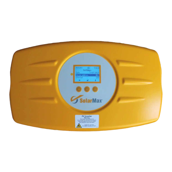
SolarMax 2000S Instruction Manual
S series, parameter configuration with maxtalk 2 pro
Hide thumbs
Also See for 2000S:
- Instruction manual (28 pages) ,
- Instruction manual (64 pages) ,
- Installation primer (28 pages)
Table of Contents
Advertisement
Advertisement
Table of Contents

Summary of Contents for SolarMax 2000S
- Page 1 SolarMax S series Parameter configuration with MaxTalk 2 pro Instruction manual...
-
Page 2: Table Of Contents
Table of contents Notes on this instruction manual Target group Scope Safety instructions used Writing styles used Safety instructions Requirements Configuration General Grid monitoring 4.2.1 Anti-Islanding (Island Detection) 4.2.2 Voltage limits 4.2.3 OV Detection 4.2.4 Frequency limits Current and output limits Leakage current limits Restart conditions 4.5.1... -
Page 3: Notes On This Instruction Manual
MaxTalk 2 can be found in the software using the “Help” menu item. Target group This instruction manual is intended for authorised skilled personnel only. Scope All data in this instruction manual exclusively applies to the following SolarMax inverters: SolarMax 2000S SolarMax 3000S SolarMax 4200S... -
Page 4: Safety Instructions
Safety instructions You are only authorised to configure the advanced functions of the SolarMax inverter if you adhere to the notes listed in the following: The grid operator must have specified and/or approved all changes. All implemented settings must be documented in writing. -
Page 5: General
Setting Description Standard VDE0126-1-1 This setting is required if an inverter of the SolarMax S series is se- lected within an existing PV system commissioned before 1 January 2012. This setting is inadmissible for PV systems commissioned after 31 December 2011. -
Page 6: Grid Monitoring
Grid monitoring The inverter constantly monitors the voltage and frequency values of the mains. If the voltage and/or frequency limits set are violated, the inverter will disconnect from the grid, upon expiration of the respective release time at the latest. 4.2.1 Anti-islanding (island Detection) With active “Anti-Islanding”, the inverter detects any existing island operation. -
Page 7: Ov Detection
example The mains voltage violates the Vac min 1 and Vac min 2 limits. Vac [V] t [s] t [s] Figure 2 Violation of voltage limits Nominal mains voltage = 230V Vac min 1 = 212V t Vac min 1 = 2500ms Vac min 2 = 196V t Vac min 2 = 500ms Mains operation... -
Page 8: Frequency Limits
4.2.4 Frequency limits The inverter permanently monitors the mains frequency for inadmissible frequency values. It is possible to specify upper and lower limits for the mains frequency. The adjustable limits for the mains frequency can be created in two stages. The tripping behaviour in the event of violations of the limits regarding the mains frequency corresponds to the tripping behaviour of voltage monitoring. -
Page 9: Leakage Current Limits
Leakage current limits Parameter Description Device Unit Ierr max Maximum admissible leakage current (effective value) on the DC 50.0 … 300.0 side. If the leakage current exceeds the set limit, the inverter will discon- nect from the mains and display the error message “Ierr too high”. Restart conditions The restart conditions can be used to specify the behaviour of the inverter when mains power is applied. -
Page 10: Reactive Power Control
Parameter Description Range of Unit values P(f) reduction Reduction of the fed-in effective power (in % of the effective power fed in when the P(f) mode was 1 … 100 %/Hz started per Hertz). f start Start frequency of the P(f) mode. The inverter will exit the P(f) mode if the mains frequency adopts values 50.00 …... -
Page 11: Q Mode
Overexcited Generator Mains unit Mains Mains -Pac Mains Mains Underexcited image 4 Generator arrow system The operating mode of the inverter must be specified for all specifications regarding reactive power and power factor. The inverter can behave as over-excited or under-excited generator unit. Operating mode “over-excited”: the inverter helps supporting the voltage at the mains connection point (quadrant I in figure 4). -
Page 12: Q(Vac) Mode
NoTe The maximum apparent power S max of the inverter cannot be exceeded. Therefore, the effective power fed in may be reduced depending on the desired amount of reactive power. The maximum effective power Pac max of the SM6000S is reduced to 4’048W, because the following relation is applicable: ;... -
Page 13: Cos(Φ) Mode
Parameter Description Range of Unit values t Q(Vac) The parameter t Q(Vac), can be used to set the delay time with 10 … 60 which the inverter is to react to changes in Vac. X-axis: Unit Range of values Y-axis Unit Range of values Voltage Vac... -
Page 14: Cos(Φ)(Pac) Mode
4.7.4 cos(φ)(Pac) mode A cos(φ) (Pac) nominal line is defined in this mode. The inverter then changes the cos(φ) value subject to the mains voltage Vac. The desired nominal line results from the specification of up to 10 pairs of values of cos(φ) and Pac. cos(φ) (Pac X0 = 0%, cos(φ) Y0) 0.800 overexcited... -
Page 15: Functions
Functions Update firmware Request the “Registration firmware update” form with the SolarMax service centre. Return the completed reg- istration form to us. Afterwards, we will provide you with the firmware update via email. The contact details can be found overleaf. -
Page 16: Synchronise Configuration
5. In order to start the update, click Update. The graphical display of the inverter will display the status message “Firmware update”. The status LED will flash red. 6. Wait for the update to end. If the update was successful, the “update successful” message will be displayed. - Page 17 SolarMax service centre Germany +49 180 276 5 276 Schweiz / Svizzera / Suisse +41 32 346 56 06 France +33 4 72 79 17 97 Italia +39 0362 312 279 España +34 902 160 626 Benelux +32 2 535 77 32 Česká...


Need help?
Do you have a question about the 2000S and is the answer not in the manual?
Questions and answers
LCD light not displaying