
Related Manuals for LaMotte Tracer PockeTester


Summary of Contents for LaMotte Tracer PockeTester
- Page 1 Tracer Salt/EC/TDS PockeTester Code 1749 Pool Professional's Meter! 1.800.561.8187 information@itm.com www. .com...
-
Page 2: Table Of Contents
TRACER SAL/EC/TDS POCKETESTER • CODE 1749 Introduction ..................4 Specifi cations ..................4 Contents ..................5 Parts & Accessories ................5 Meter Description Front Panel Description ............... 6 TRACER Display ................6 Basic Operation Powering the TRACER ..............7 Automatic Calibration ..............7 TDS Compensation Ratio ............7 To Change the TDS Conversion Ratio ........ -
Page 3: Introduction
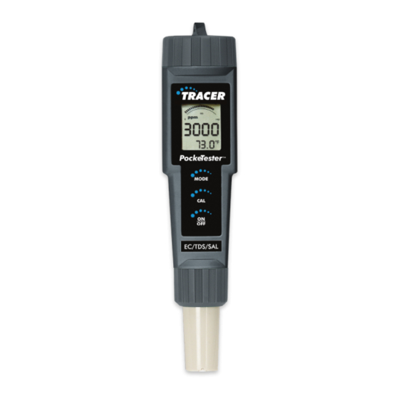
INTRODUCTION Congratulations on your purchase of the SAL/EC/TDS (Conductivity/Total Dissolved Solids/Salinity) TRACER PockeTester. The TRACER offers direct reading of salinity, conductivity, and TDS with one electrode. Careful use and maintenance will provide years of reliable service. SPECIFICATIONS Display 2000 count LCD with Bar Graph Conductivity Range 0 to 199.9 μS... -
Page 4: Contents
CONTENTS SAL/EC/TDS TRACER PockeTester Kit Code 1749 Includes: Salinity Standard, 3,000 ppm Code 6005-G Sample Cup w/cap † † Not sold individually. See below. PARTS & ACCESSORIES SAL/EC/TDS Replacement Electrode Code 1765 Weighted Stand w/Sample Cups (5) Code 1746 Sample Cups w/caps (24) Code 1745 Conductivity Standard, 84 μS, 30 mL... -
Page 5: Meter Description Front Panel Description
METER DESCRIPTION Front Panel Description Battery compartment cap LCD Display MODE button - change mode, hold data, store data CAL button - calibration, change temperature units, recall data ON/OFF button Electrode Collar Electrode (Note: The Electrode cap is not shown) TRACER Display Bar graph display Main display... -
Page 6: Basic Operation Powering The Tracer
BASIC OPERATION Powering the TRACER The Tracer uses four CR2032 Lithium Ion batteries. If the batteries are weak, indicator will appear on the display. Press the ON/OFF key to turn the TRACER on or off. The auto power off feature will shut the TRACER off automatically after ten minutes of inactivity. -
Page 7: Changing Temperature Units
Changing Temperature Units To change the displayed temperature units between °F or °C: With the TRACER off, press and hold the CAL button. With the CAL button pressed, momentarily press the ON/OFF button. SELF CAL When appears in the display, release the CAL button. The TRACER will return to the operational mode with the temperature dis- played in the new units. -
Page 8: Testing Getting Started
TESTING Getting Started Remove the cap from the bottom of the TRACER to expose the electrode. Before the fi rst use, rinse the electrode in deionized water and dry. For best results, calibrate for conductivity with a standard in the expected range of the sample. -
Page 9: Measurement
Measurement Fill a sample cup to the 20 mL line with the test sample. Sample depth must be greater than or equal to 1.5 inches. Immerse the TRACER electrode in the sample. Make sure the electrode is completely submersed. Press the ON/OFF button. (8888 and then SELF CAL will appear in the display during the initial diagnos- tics). -
Page 10: Storing Readings
Filter the contents of the fl ask. Collect the fi ltrate in a beaker. Rinse the electrode with distilled or deionized water to remove impurities. Press the ON/OFF button to turn the TRACER on. Make sure the meter is in the TDS mode. Immerse the electrode in the fi... -
Page 11: Clearing The Memory
The last stored reading taken will be displayed fi rst. To advance to the previously stored readings, press the MODE button. The location number is displayed fi rst, followed by the reading stored in that location. To exit the storage mode, press the CAL button and the TRACER will return to normal operation after displaying “End”. - Page 12 The calibration range indicator will appear on the display for each range that is calibrated during a power on cycle. Low Range, 84 μS/cm Medium Range, 1413 μS/cm or 3,000 ppm SaH High Range, 12.88 mS/cm (12,880 μS/cm) NOTE: Each time the calibration mode is entered all calibration range indicators will be cleared, but only the calibration data for the currently selected range will be replaced.
-
Page 13: Operational Matrix
OPERATIONAL MATRIX Function/ Resulting Action Power Mode Key Press Sequence On/Off On or Momentary press of ON/OFF button Calibration Press & hold CAL button for 2 seconds until CAL is displayed Store Reading Momentary press of MODE button Hold Release Hold Momentary press of MODE button... - Page 14 Function/ Resulting Action Power Mode Key Press Sequence Enter CON/TDS Press and release the Ratio (ppm or CAL button twice in mg/L) quick succession. Change CON/TDS Momentary press of Ratio (ppm or MODE button. Each mg/L) press increases ratio by 0.1 from 0.4 to 1.0.
-
Page 15: Maintenance Storage
MAINTENANCE Storage Rinse the electrode in distilled or deionized water. Store the electrode dry with the cap on. Always rinse the electrode in deionized water between measurements to avoid cross contamination. Double rinsing is recommended when high accuracy is required. Battery Replacement Twist off the battery compartment cap. -
Page 16: Replacing The Electrode
Replacing the electrode Unscrew and remove the electrode collar. Turn collar counter-clockwise. Gently rock the electrode side to side, while pulling it away from the meter, until it disconnects from the electrode socket. To attach an electrode, align the slots and carefully plug the electrode into the meter socket. -
Page 17: Troubleshooting
TROUBLESHOOTING Problem Check Action Reading is frozen HOLD mode Press MODE button to exit HOLD mode “BAT” message Batteries low Replace batteries Meter will not Trapped air Tap probe or stir sample to calibrate bubbles release air bubbles Dirty probe Clean probe Damaged Replace probe... -
Page 18: Warranty
WARRANTY LaMotte Company warrants this instrument to be free of defects in parts and workmanship for 1 year from the date of shipment and the probe to be free of defects in parts and workmanship for 6 months from the date of shipment. If it...
Need help?
Do you have a question about the Tracer PockeTester and is the answer not in the manual?
Questions and answers