Table of Contents

Related Manuals for Federal Signal Corporation 310LD-MV


Summary of Contents for Federal Signal Corporation 310LD-MV
- Page 1 MODEL 310LD-MV Audio Master CALL LISTEN TALK FEDERAL SIGNAL CORPORATION UNIVERSITY PARK, IL. U.S.A. WARNING: DISCONNECT POWER BEFORE REMOVING COVER INSTALLATION AND SERVICE INSTRUCTIONS 2561328A REV. A 1108 Printed in U.S.A.
- Page 2 INSTALLATION AND SERVICE INSTRUCTIONS MODEL 310LD-MV SAFETY MESSAGE TO INSTALLERS, USERS AND MAINTENANCE PERSONNEL It is important to follow all instructions shipped with this prod- uct. This device is to be installed by a trained electrician who is thoroughly familiar with the National Electrical Code and will follow NEC Guidelines as well as local codes.
-
Page 3: General Features
Master or Slave mode configurations. A call button with remote call dry contacts is also factory supplied in the unit. The 310LD-MV has a NEMA 1 enclosure and is a UL Listed and CSA Certified signal appliance. -
Page 4: Slave Mode
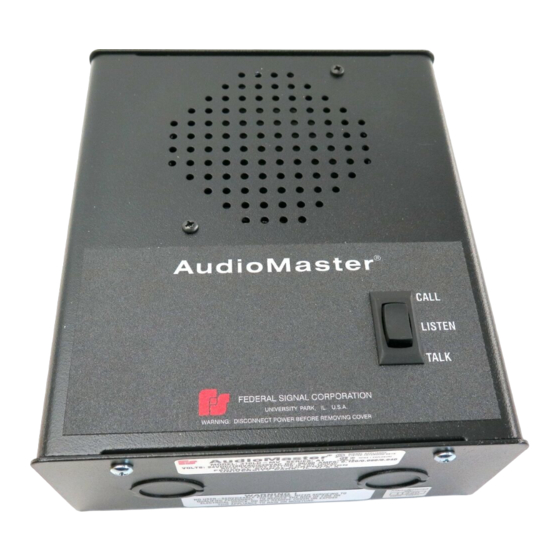
Audio Master CALL LISTEN TALK FEDERAL SIGNAL CORPORATION UNIVERSITY PARK, IL. U.S.A. WARNING: DISCONNECT POWER BEFORE REMOVING COVER 290A3077 Figure 2. master mode. When the switch is released it will default back to the Listen or Speaker mode, allowing the user to receive any messages transmitted back to it. -
Page 5: Remote Control
REMOTE CONTROL: Remote control is used to change the operation mode of a remote intercom from listen to talk or from talk to listen upon activation of a local intercom. The wiring diagram section illustrates Master/Slave Installation and Using Foot Switches Diagrams. (See figures 5 and 6.) Normally open foot switches can also be connected to the Remote Control line and ground in order to allow “hands free”... - Page 6 24VDC IN/OUT GROUND REMOTE CONTROL REMOTE SPEAKER COMMON PHASE EXT CALL CONTACT GROUND CLASS I WIRING CLASS II WIRING 290A3078 Figure 3. ISOLATED BALANCED/UNBALANCED LINES: The audio signals for the 310 are transmitted over a wire pair using balanced line technology. This means each wire carries a signal that is opposite in polarity of the other.
- Page 7 MODEL 310LD-MV SPECIFICATIONS Operating Voltage 24 Vdc, 120 Vac and 240 Vac 50/60 Hz Current Draw Voltage Operating Standby 24 Vdc 120 mA 60 mA 120 Vac 80 mA 60 mA 240 Vac 40 mA 30 mA : The 24 Vdc input must be limited to 760 mA out if run from a supply.
-
Page 8: Electrical Connections
B. UNPACKING. After unpacking the Model 310LD-MV, examine it for damage that may have occurred in transit. If the equipment has been dam- aged, do not attempt to install or operate it, file a claim immediately with the carrier stating the extent of the damage. Carefully check all envelopes, shipping labels and tags before removing or destroying them. - Page 9 The signal lines, remote control lines, remote power, and call dry con- tacts are landed in a seven-position terminal block (J7) in the Class II wiring compartment. The two wiring sections are isolated by a fishpa- per barrier. Disconnect power to the intercom before any installation, maintenance, or configuration changes are performed.
-
Page 10: Replacement Parts
8.00 7.125 Audio Master CALL LISTEN TALK FEDERAL SIGNAL CORPORATION UNIVERSITY PARK, IL. U.S.A. WARNING: DISCONNECT POWER BEFORE REMOVING COVER BACK FRONT CLASS I WIRE ENTRY 3.50 4 x .202 5.50 Audio Master COMBINATION 1/2"-3/4" KNOCK-OUT 3.05 CLASS II WIRE ENTRY 1.40... -
Page 11: Wiring Diagrams
G. WIRING DIAGRAMS. INTERCOM I MASTER/SLAVE INSTALLATION INTERCOM II 310LD-MV MASTER 310LD-MV SLAVE 24 VDC 24 VDC GROUND GROUND REMOTE REMOTE AUDIO + AUDIO + AUDIO AUDIO DRY CONTACT DRY CONTACT 1 WATT DRY CONTACT DRY CONTACT NEUTRAL NEUTRAL EARTH GND. - Page 12 INTERCOM I USING CALL DRY INTERCOM II 310LD-MV MASTER CONTACTS WITH AC 310LD-MV SLAVE 24 VDC 24 VDC 1 WATT GROUND GROUND REMOTE REMOTE AUDIO + AUDIO + AUDIO AUDIO DRY CONTACT DRY CONTACT DRY CONTACT DRY CONTACT POWER POWER...
- Page 13 INTERCOM I BASIC BALANCED INTERCOM II 310LD-MV MASTER LINE SYSTEM 310LD-MV SLAVE 24 VDC 24 VDC GROUND GROUND REMOTE REMOTE AUDIO + AUDIO + AUDIO AUDIO DRY CONTACT DRY CONTACT 1 WATT DRY CONTACT DRY CONTACT NEUTRAL NEUTRAL EARTH GND.
- Page 14 INTERCOM I BASIC UNBALANCED 310LD-MV MASTER LINE SYSTEM 24 VDC GROUND REMOTE 1 WATT CABLE AUDIO AUDIO + GROUND AUDIO DRY CONTACT DRY CONTACT NEUTRAL EARTH GND. 290A3086 Basic Unbalanced Line System This configuration is used when hooking to other products on the market.
- Page 15 INTERCOM I MULTIPLE INTERCOMS INTERCOM 2 310LD-MV MASTER 310LD-MV SLAVE 24 VDC 24 VDC GROUND GROUND REMOTE REMOTE 1 WATT AUDIO + AUDIO + AUDIO AUDIO DRY CONTACT DRY CONTACT DRY CONTACT DRY CONTACT NEUTRAL NEUTRAL EARTH GND. EARTH GND.
- Page 16 back page...
Need help?
Do you have a question about the 310LD-MV and is the answer not in the manual?
Questions and answers