Advertisement
Quick Links
AD-26P, AD-27P, AD-56P and AD-57P
Atkinson Dynamics Panel Mount Intercoms
Installation and Maintenance Manual
2645 Federal Signal Drive, University Park, Illinois 60484
Customer Support +1-708-534-4756, iordersup@fedsig.com
Technical Support 1-800-755-7621 +1-708-587-3587, signalsupport@fedsig.com
www.fedsig.com
2561542
Rev. E2 620
Printed in U.S.A.
© 2020 Federal Signal Corporation
Advertisement

Subscribe to Our Youtube Channel
Related Manuals for Federal Signal Corporation AD-26P


Summary of Contents for Federal Signal Corporation AD-26P
- Page 1 AD-26P, AD-27P, AD-56P and AD-57P Atkinson Dynamics Panel Mount Intercoms Installation and Maintenance Manual 2645 Federal Signal Drive, University Park, Illinois 60484 Customer Support +1-708-534-4756, iordersup@fedsig.com Technical Support 1-800-755-7621 +1-708-587-3587, signalsupport@fedsig.com www.fedsig.com 2561542 Rev. E2 620 Printed in U.S.A. © 2020 Federal Signal Corporation...
- Page 2 INSTALLATION AND SERVICE INSTRUCTIONS FOR ATKINSON DYNAMICS PANEL MOUNT INTERCOMS Safety Messages to Installers, Users, and Maintenance Personnel It is important to follow all instructions shipped with this product. This device is intended to be installed by a trained electrician who is thoroughly familiar with the National Electrical Code and will follow NEC Guidelines as well as local codes.
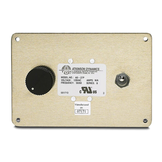
- Page 3 Model AD-26P AD-56P AD-27P AD-57P 120 VAC, 240 VAC, Supply Voltage 12 VDC 24 VDC 50/60 Hz 50/60 Hz Audio Power Output (Max.) 8.0 watt 11.7 watt 11.3 watt 11.3 watt Power Consumption (Max.) 20.0 watt 39.6 watt 28.8 watt 30.5 watt...
-
Page 4: Call Button
CALL BUTTON: “A” Models are equipped with a Call switch. Depressing the call switch transmits an 890 Hz tone to all units in the intercom system. The volume of the call signal is affected by the volume control on the receiving unit, so if volume is turned all the way down at a receiving station, the call signal will not be heard. - Page 5 D. Mounting. The selection of the mounting location for the device, its controls, and the routing of the wiring are to be accomplished under the direction of the facilities and the safety engineer. The panel mount intercom is designed to be mounted behind a customer-supplied panel. 1.
- Page 6 2. Replacement Parts. Replace fuse with GMC-1/2 only. DO NOT substitute. Description Part Number Kit, PC Board, 12V, AD-26C K2001878B-01 Kit, PC Board, 12V, AD-26D K2001878-02 Kit, PC Board, 24V, AD-56 K2001878-07 Kit, PC Board, 24V, AD-56C K2001878-08 Kit, PC Board, 12V, AD-26-8-M44 K2001896B Kit, potentiometer with on/off switch K8590236A...
-
Page 8: Operating Principle
REMOTE SECONDARY SPEAKER AD-SF-25/AD-SS-25 LOCAL SPEAKER/MICROPHONE MODEL AD-SF-25 "SPK" SPEAKER (WHT/BRN) 200 FT. MAX. "COM" COMMON (WHT) PRIMARY PANEL MOUNTED INTERCOM "REM SPK" "COM" COMMON REMOTE (WHT) SPEAKER (BLK) 1WATT SEE POWER CONNECTIONS 290A3828-02 "PWR " (BLK) "PWR " (WHT) Power Connections: "PWR+"... - Page 12 PANEL MOUNT TEMPLATE 290A3828-07...
Need help?
Do you have a question about the AD-26P and is the answer not in the manual?
Questions and answers