Table of Contents
Advertisement
Quick Links
Advertisement
Table of Contents

Related Manuals for Hanna Instruments edge DO


Summary of Contents for Hanna Instruments edge DO
- Page 1 ®...
- Page 2 If you need additional technical information, do not hesitate to e‑mail us at tech@hannainst.com or view our worldwide contact list at www.hannainst.com. All rights are reserved. Reproduction in whole or in part is prohibited without the written consent of the copyright owner, Hanna Instruments Inc., Woonsocket, Rhode Island, 02895, USA.
-
Page 3: Table Of Contents
Included ..........................Safety Measures ......................... Description ......................... Diagram ..........................Product Diagram ......................Probe Diagram ......................Keypad Function ......................Guide to Indicators ..................... Setup/Installation ....................... Setting Up edge ....................® DO Electrode & Probe Connections ..................General Setup ......................Logging Function ....................... Viewing Logged Data .................... -
Page 4: Included
Remove the instrument from the packing material and examine it carefully to make sure that no damage has occurred during shipping. If there is any damage, please contact your local Hanna Instruments Office. Each instrument edge (HI2004) is supplied with: ®... -
Page 5: Description
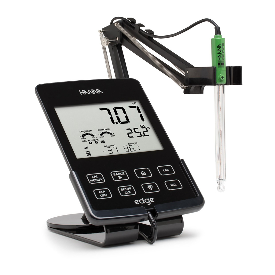
® DO Hanna Instruments edge digital sensors for Dissolved Oxygen. Each digital sensors has a unique ® DO serial number that is automatically identified by the meter. Once connected to the meter, the sensor is ready to measure dissolved oxygen along with temperature. - Page 6 Liquid Crystal Display (LCD) Micro USB device connection for power or Capacitive Touch Keypad PC interface 3 mm jack input for edge digital Standard USB host connection for data ® DO probes transfer to a USB thumb‑drive Top mounted ON/OFF button...
-
Page 7: Probe Diagram
PROBE DIAGRAM DO Electrode • Probes process signal directly for noise free measurements • Auto sensor recognition • Store calibration specific data from the last calibration • Are built with materials suitable for use in chemical analysis • Have integrated temperature measurement •... -
Page 8: Keypad Function
KEYPAD FUNCTION 1. CAL/MODIFY ‑ Used to enter and exit calibration mode. In SETUP, used to initiate changes of a configuration setting. 2. GLP/CFM ‑ Used to display GLP calibration information. In SETUP, used to confirm change made. In calibration, used to accept calibration points. 3. -
Page 9: Guide To Indicators
GUIDE TO INDICATORS Mode tags Labels Confirm tag Second LCD line, temperature USB connection status measurement Probes symbol 10. Temperature units Battery symbol 11. Temp. Compensation status Arrow tags, displayed when they are 12. Measurement line available 13. Measurement units Third LCD line, message area 14. -
Page 10: Setup/Installation
SETTING UP edge ® DO The main operating modes of edge are setup, calibration, measurement, data logging, and data ® DO export. Follow this general outline of steps to get you started. The following topics are expanded upon in the sections that follow in this manual. Familiarize yourself with the design features of this unique meter. - Page 11 Slide edge into the cradle while positioning the probe cable behind the cradle. ® DO Put the probe/sensor into the electrode holder and secure cable in clips. Connect the power adapter cable to the rear socket of the bench cradle. Connect the other end to the power adapter and plug into line power.
- Page 12 Connect the power adapter cable to the bottom socket of the wall cradle. Connect the other end to the power adapter and plug into line power. Connect the 3 mm probe jack to the socket located at the bottom of edge ®...
-
Page 13: Electrode & Probe Connections
ELECTRODE & PROBE CONNECTIONS Connect the 3 mm probe jack to the probe input located on the bottom of edge . Make sure the probe ® DO is completely connected. If the probe is recognized, “CONNECTING” message is displayed along with sensor model. -
Page 14: General Setup
GENERAL SETUP The following General Setup options are displayed regardless of the sensor being used. These settings remain when switching to another probe type or when no probe is attached. Options are tabulated in the table below with choices and default values. Options are accessed by pressing SETUP/CLR key. Loop through the options by using the keys. - Page 15 Option Description Choices Default Used to save battery life by automatically turning off when no 5, 10, 30, 60 Min Set Auto Off key press is detected for time set 10 MIN or Off and meter is not in active logging or calibration mode.
-
Page 16: Logging Function
LOGGING FUNCTION Note: If powering edge through the micro USB connector to a PC, a SETUP option will ® DO require the choice “LOG ON EDGE” or “EXPORT TO PC“. 1000 log records can be stored into edge memory. This memory is shared between and ®... - Page 17 A “PLEASE WAIT” message will be displayed followed by the number of free spaces. During active interval logging, lot information is displayed on the third LCD line. The line indicates in which lot the data will be placed and keeps track of the number of logged records taken. The “LOG“...
-
Page 18: Viewing Logged Data
Stability Logging Select Stability and choose measurement stability criteria in the SETUP menu. To initiate the Stability log, press the LOG key while the instrument is in measurement. The “PLEASE WAIT” screen will be displayed briefly followed by a screen showing the stability tag, “LOG” tag and a “WAITING” message. The log can be stopped while the “WAITING”... - Page 19 If no data was logged for the selected measurement range, the instrument displays the following messages: • “NO MANUAL LOGS” • “NO STABILITY LOGS” Press GLP/CFM key to enter inside lot information to view recorded data. Use the keys to toggle between different records. Use RANGE/ to display GLP data including calibration information, date, time, etc.
- Page 20 Press GLP/CFM key. The instrument will display “PLEASE WAIT” and then “CLEAR DONE” message. When individual logs are deleted within saved MANUAL or STABILITY logs, the logs will renumber, filling in the deleted data but staying in chronological order. To delete all records of the MANUAL (STABILITY) log, proceed as described on page 19 for LOTS. Select the Manual (Stability) lot and press SETUP/CLR key.
-
Page 21: Pc & Storage Interface
PC & STORAGE INTERFACE Logged data on edge can be transferred from the meter to a USB flash drive by using the log ® DO recall function. The minimum requirement for the drive is USB 2.0. Select the DO record you wish to export and follow the simple steps below. - Page 22 Logged data on the edge can be transferred from the meter to a PC by following these simple ® DO directions. Suitable operating systems include Windows (XP minimum), OS X or Linux. Connect edge to the PC using the supplied micro USB cable. ®...
-
Page 23: Operational Guide
Do not drop or handle carelessly. Probes from Hanna Instruments are shipped dry. 1. Carefully remove the cardboard shipping tube used to protect the probe during shipping. Save the tube, should the probe be stored dry again. -
Page 24: Dissolved Oxygen Probe Diagram
During this process, the following message will be displayed on the LCD, “DISSOLVED OXYGEN PROBE CONDITIONING”. The conditioning message will be displayed for about 60 seconds while the DO probe is conditioned. If the probe was conditioned and a new conditioning is not necessary, press any key to enter measurement mode. -
Page 25: Dissolved Oxygen Meter Configuration
DISSOLVED OXYGEN METER CONFIGURATION DO (Dissolved Oxygen) meter operation is configured using the SETUP key with a DO probe connected to the meter. The parameter‑specific options will be seen inserted into the menu. Parameter Description Choices Default Concentration measurements of dissolved ‑500, ‑400, ‑300, ‑200, ‑100, oxygen change depending 0, 100, 200, 300, 400, 500,... -
Page 26: Dissolved Oxygen Calibration
Salinity and Altitude Compensation Temperature, altitude and salinity compensation are used for DO concentration measurements (ppm or mg/L). When the water is colder, it can hold more dissolved oxygen, when it is warmer it holds less oxygen. Compensation for temperature‑related solubility is done automatically using the built‑in temperature sensor within the DO probe and algorithms in edge . - Page 27 Calibrate the probe frequently, especially if high accuracy is required. The probe can be calibrated at 2 points: 100.0 % (slope calibration) and 0.0 % (zero calibration). Initial Preparation Prepare a fresh bottle of HI7040 by following package directions. Use solution within one month of preparation.
-
Page 28: Dissolved Oxygen Calibration Messages
DISSOLVED OXYGEN CALIBRATION MESSAGES If the reading is outside limits, “WRONG STANDARD“ message will be displayed. If the temperature is out of range (0.0 ‑ 50.0 ºC) during calibration, then the message “WRONG STANDARD TEMPERATURE” will be displayed and temperature value will blink. DISSOLVED OXYGEN GLP INFORMATION GLP refers to a quality control function used to ensure uniformity of probe calibrations and measurements. -
Page 29: Dissolved Oxygen Measurements
The date of the calibration together with the current reading. Calibration Expiration status together with the current reading: If disabled, “EXPIRATION WARNING DISABLED” is displayed. If enabled, the number of days until the calibration alarm “CAL DUE” will be displayed. (i.e. “CAL EXPIRES IN 2 DAYS”) If enabled, the number of days the calibration has expired (i.e. - Page 30 Oxygen is consumed during the measurement. For accurate DO measurements, water movement of 0.3 m/s is suggested. This is to ensure that the oxygen‑depleted membrane surface is constantly measuring a representative sample. Is recommended to use magnetic stirrers. The probe has a built‑in temperature sensor.
-
Page 31: Maintenance
DISSOLVED OXYGEN PROBE MAINTENANCE The DO probe body is made of PEI. Use the protective cap when the probe is not in use. To replace the membrane or refill with electrolyte, proceed as follows: For a new probe, remove the protective shipping tube by gently twisting and pulling it off the body of the probe (see fig. -
Page 32: Troubleshooting Guide
LCD line. At startup the meter Check the keyboard or contact your displays all LCD tags One of the keys is stuck. local Hanna Instruments Office. permanently. Instrument was not factory CAL “Prod” message at Contact your local Hanna calibrated or lost factory startup. -
Page 33: Specifications
Dissolved Oxygen Specifications 0.00 to 45.00 ppm (mg/L); Range 0.0 to 300.0%; 0.01 ppm (mg/L); Resolution 0.1%; Accuracy ±1.5% of reading ±1 digit; @ 25 °C / 77 °F Calibration One or two points at 0% (HI7040) and 100% (water saturated air) Temperature 0.0 to 50.0 ºC;... -
Page 34: Accessories
HI7040L Zero Oxygen Solution HI7041S Refilling Electrolyte Solution, 30 mL HI764080 Spare DO probe HI764080A/P 5 spare membranes Other Accessories HI75110/220U Voltage adapter from 115 VAC to 5 VDC (USA plug) HI75110/220E Voltage adapter from 230 VAC to 5 VDC (European plug) HI76404W Electrode holder HI2000WCW... - Page 35 If the repair is not covered by the warranty, you will be notified of the charges incurred. If the instrument is to be returned to Hanna Instruments, first obtain a Returned Goods Authorization (RGA) number from the Technical Service department and then send it with shipping costs prepaid.
- Page 36 World Headquarters Hanna Instruments Inc. Highland Industrial Park 584 Park East Drive Woonsocket, RI 02895 USA www.hannainst.com Local Office Hanna Instruments USA 270 George Washington Highway Smithfield, RI 02917 Phone: 800.426.6287 Fax: 401.765.7575 e‑mail: tech@hannainst.com MANEDGEDO Printed in ROMANIA...
Need help?
Do you have a question about the edge DO and is the answer not in the manual?
Questions and answers