Table of Contents
Advertisement
Advertisement
Table of Contents

Related Manuals for Hanna Instruments edge EC HI2003


Summary of Contents for Hanna Instruments edge EC HI2003
- Page 1 ®...
-
Page 2: Table Of Contents
Hanna representative near you at www.hannainst.com. All rights are reserved. Reproduction in whole or in part is prohibited without the written consent of the copyright owner, Hanna Instruments Inc., Woonsocket, Rhode Island, 02895 , USA Table of Included ...............................3... -
Page 3: Table Of Included
Remove the instrument & accessories from the packaging and verify damage Included has not occurred during shipping. Remove protective lm from meter. Notify your nearest Hanna Customer Service Center if damage is observed. Each instrument is supplied with: edge ® (HI2003) Bench cradle Wall cradle Electrode holder... -
Page 4: Description
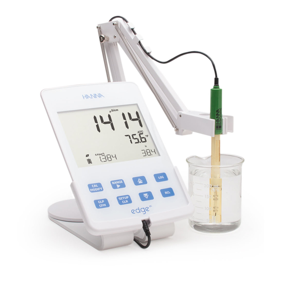
Description edge ® enables the user to make fast, accurate measurements of commonly measured laboratory parameters using one of the Hanna edge ® digital sensors for Conductivity. Each digital sensors has a unique serial number. Once connected to the meter, the sensor(s) are ready to measure their parameter along with temperature. -
Page 5: Product Diagram
Product Diagram Liquid Crystal Display (LCD) Micro USB device connection for Capacitive Touch Keypad power or PC interface 3 mm jack input for edge ® Standard USB host connection digital probes for data transfer to a USB Top mounted ON/OFF button thumb-drive Diagram... -
Page 6: Probe Diagram
Probe Diagram Probe EC Electrode • Probes process signal directly for noise free measurements • Auto sensor recognition • Store calibration speci c data from the last calibration • Are built with materials suitable for use in chemical analysis • Have integrated temperature measurement •... -
Page 7: Keypad Function
Keypad Function CAL/MODIFY - Used to enter - Used to scroll through exit calibration mode. SETUP menu. Used change SETUP, used to initiate changes of a selection when modifying con guration setting. parameter in SETUP. GLP/CFM - Used to display GLP RCL (Recall) - Used to view calibration information. -
Page 8: Guide To Indicators
Guide to Indicators Mode tags Second LCD line, temperature Con rm tag measurement USB connection status 10. Temperature units Probes symbol 11. Temp. Compensation status Battery symbol 12. Measurement line Arrow tags, displayed when they 13. Measurement units are available 14. -
Page 9: Setup/Installation
The main operating modes of edge ® are setup, calibration, measurement, Setup/ data logging, and data export. Follow this general outline of steps to get you Installation started. The following topics are expanded upon in the sections that follow in this manual. -
Page 10: Electrode & Probe Connections
Setting Up edge ® Connect the power adapter cable to the bottom socket of the wall cradle. Connect the other end to the power adapter and plug into line power. Connect the 3mm probe jack to the socket located at the bottom of edge ®. -
Page 11: General Setup
The following General Setup options are displayed regardless of the sensor General being used. These settings remain when switching to another probe type or Setup when no probe is attached. Options are tabulated in the table below with choices and default values. Options are accessed by pressing SETUP. Loop through the options by using the pq arrows. - Page 12 General Option Description Choices Default Basic mode Setup Used to save battery life by automatically turning o when 5, 10, 30, 60 no key press is Set Auto O 10 min Available detected for or O time set and meter is not in active logging or calibration mode.
-
Page 13: Basic Mode
edge ® o ers a basic operation mode that streamlines measurement Basic Mode con guration for EC measurements and is useful for many routine applications. Basic EC reduces speci c EC SETUP parameters to 3. The meter defaults settings to common parameters and auto ranges measurements automatically. The Basic EC meter may be used for conductivity and TDS measurements (salinity is not available). - Page 14 Logging In Setup mode, choose log parameter, press MODIFY then use the u arrow to select between Interval, Manual, or Stability. When Interval is displayed, use the Function p and q arrows to select the setting for the timed interval. When Stability is displayed, use the p and q to select the measurement stability setting.
-
Page 15: Viewing Logged Data
Stability Logging Logging Select Stability and choose measurement stability Function criteria in the SETUP menu. Only Stability Medium is available in Basic mode. To initiate the Stability log, press the LOG key while the instrument is in measurement. The “PLEASE WAIT” screen will be displayed brie y followed by a screen showing the stability tag, “LOG”... - Page 16 Viewing Delete Logging Type/Lot Logged Press RCL and select the parameter log. Data Use the pq keys to select the Manual/Stability records or Interval lots to delete. Press CLR. The instrument will display “CLEAR MANUAL” for Manual Records, “CLEAR STAB” for Stability Records. For Interval lots, the message “CLEAR”, followed by the selected lot will be displayed with “CFM”...
- Page 17 Viewing The lot number is used to identify particular sets of data. The lot numbers Logged are allocated successively until 100, even if some lots were deleted. The total Data number of lots that can be saved is 100. If some are deleted (for example 1-50), fty additional logs may be stored.
-
Page 18: Pc & Storage Interface
PC & Storage Logged data on edge ® can be transferred from the meter to a USB ash drive by using the log recall function. The minimum requirement for the drive is USB Interface 2.0. Select the EC record you wish to export and follow the simple steps below. Connect USB ash drive to the USB port, located on the top of the meter. - Page 19 Logged data on the edge ® can be transferred from the meter to a PC by PC & Storage following these simple directions. Suitable operating systems include Windows Interface (Xp minimum), OS X or Linux. Connect edge ® to the PC using the supplied micro USB cable. Turn on edge ®.
-
Page 20: Operational Guide
Operational Steps To Optimize EC Measurement Follow these steps to optimize measurement using an EC probe: Guide Determine what measurement you wish to make with the EC probe. (See below) Basic vs Standard Determine if Standard or Basic mode is best for your measurement. EC Mode Connect the Probe and con gure your measurement using the SETUP menu. - Page 21 EC Meter Option Description Choices Default Basic mode Con guration Basic Mode O or On Available Temperature The user No TC or ATC Not available. Compensation may select ATC is Automatic automatically Temperature used. Compensation or No TC to con gure absolute conductivity.
- Page 22 EC Meter Option Description Choices Default Basic mode Con guration EC Range If AUTO is used, AUTO, AUTO Not available but 29.99 μS/cm, measurement edge ® will 299.9 μS/cm, autoranges as automatically 2999 μS/cm, needed. nd the correct 29.99 mS/cm, conductivity 200.0 mS/cm, range and...
-
Page 23: Ec/Tds Calibration
Press CFM. The message “MANUAL CALIBRATION CLEARS PREVIOUS EC Meter CALIBRATIONS” will be displayed on the third line LCD. “CAL” and “CFM” tags Con guration will blink. Press CFM to con rm the manual calibration. Note: GLP will display “Manual” for a standard. Using this calibration technique will erase any previous calibrations done in CAL. - Page 24 EC/TDS Press CAL to enter calibration. The “CAL” tag and the recognized standard value will appear on the third Calibration LCD line. If necessary, press the ARROW keys to select a di erent standard value. The “ “ along with “STIR” tag will be displayed and “WAIT”...
-
Page 25: Nacl % Calibration
NaCl % Preparation Pour a small quantity of the calibration solution into a beaker. If possible, use a Calibration plastic beaker to minimize any EMC interferences. Before pressing CAL verify in SETUP: • Basic mode is o . • Salinity Scale is set to NaCl%. In measurement mode use the RANGE key to select the Salinity measurement. - Page 26 Calibration Wrong Standard Temperature Messages If the temperature is out of the 0.0 to 60.0 ºC range, “WRONG STANDARD TEMPERATURE” message will be displayed and the temperature value will blink. EC/TDS GLP GLP is a set of functions that allows storage and retrieval of data regarding the Information maintenance and status of the electrode.
-
Page 27: Ec/Tds Glp Information
EC/TDS GLP The reference temperature together with the current Information reading. The time (hh:mm:ss) of the last calibration together with the current reading. The date (yyyy.mm.dd) of the last calibration together with the current reading. Calibration Expiration status together with the current reading: If disabled, “EXPIRATION WARNING DISABLED”... - Page 28 NaCl % GLP NaCl % Calibration Data in GLP Information To view the NaCl% calibration data, press GLP when the instrument is in NaCl% measurement mode. Use the ARROW keys to scroll through the calibration data. The instrument will display the calibration temperature and solution. The cell factor in cm determined from the calibration with the current reading.
-
Page 29: Nacl % Glp Information
NaCl % GLP If enabled, the number of days since the calibration Information expired. (i.e. “CAL EXPIRED 2 DAYS AGO”). The serial number of the probe. Note: Press GLP at any moment and the instrument will return to measurement mode. The RANGE key will change measurement from conductivity to TDS to Salinity. - Page 30 EC/TDS No Temperature Compensation (No TC): The temperature value is displayed, but not taken into account. When this option is selected, the “NoTC” tag will be Measurements displayed. The reading displayed on the primary LCD is the uncompensated EC or TDS value. Note: •...
- Page 31 Note: Salinity • These are for determining salinity as they relate to general oceanographic Measurements use. • Practical salinity and the Natural Seawater require a conductivity calibration. • NaCl % requires a calibration in HI 70371 standard. PSU - Practical Salinity Units The practical salinity (S) of seawater relates the ratio of electrical conductivity of a normal seawater sample at 15 ºC and 1 atmosphere to a potassium chloride solution (KCl) with a mass of 32.4356 g/Kg water at the same temperature and...
-
Page 32: Salinity Measurements
Salinity If the reading is out of range, the full-scale value Measurements (400.0%) will be displayed blinking. Natural Sea Water Scale The Natural Sea Water Scale extends from 0 - 80.0 g/L. It determines salinity based upon a conductivity ratio of sample to “standard seawater” at 15 °C. Where R is the conductivity ratio and salinity is de ned by the following equation:... -
Page 33: Maintenance
Maintenance Rinse the probe with clean water after measurements. If a more thorough cleaning is required, remove the probe sleeve and clean the probe with a cloth EC Probe or a nonabrasive detergent. Make sure to reinsert the sleeve onto the probe Maintenance properly and in the right direction. -
Page 34: Troubleshooting Guide
Troubleshooting Symptoms Problems Solution Guide Reinstall the sleeve. Tap the probe to EC probe sleeve not Readings uctuate up remove air bubbles. Move to center properly inserted; air and down (noise). of beaker. Verify top hole in sleeve is bubbles inside sleeve. covered with solution. -
Page 35: Speci Cations
Speci cations Salinity 0.00 to 29.99 μS/cm, 0.00 to 14.99 ppm (mg/L), 30.0 to 299.9 μS/cm, 15.0 to 149.9 ppm (mg/L), 300 to 2999 μS/cm, 150. to 1499. ppm (mg/L), 0.0 to 400.0% NaCl *, 3.00 to 29.99 mS/cm, 1.50 to 14.99 g/L, Range 2.00 to 42.00 PSU *, 30.0 to 200.0 mS/cm,... - Page 36 Speci cations Additional Speci cations PC Interface Micro USB Storage Interface Power Supply 5 VDC Adapter (included) Environment 0-50 ºC (32-122 ºF) Max 95% RH non-condensing Dimensions 202 x 140 x 12 mm (7.9 x 5.5 z 0.5”) Weight 250g (8.82 oz) Speci cations...
-
Page 37: Accessories
Accessories Probes HI 763100 EC/temperature probe Conductivity Solutions HI 70030P 12880 μS/cm, 20 mL sachets (25 pcs.) HI 70031P 1413 μS/cm, 20 mL sachets (25 pcs.) HI 70039P 5000 μS/cm, 20 mL sachets (25 pcs.) HI 7030M 12880 μS/cm, 230 mL bottle HI 7031M 1413 μS/cm, 230 mL bottle HI 7033M... -
Page 38: Warranty
If the repair is not covered by the warranty, you will be noti ed of the charges incurred. If the instrument is to be returned to Hanna Instruments, rst obtain a Returned Goods Authorization number from the Technical Service department and then send it with shipping costs prepaid. - Page 39 Hanna Instruments reserves the right to modify the design, construction or appearance of its products without advance notice.
Need help?
Do you have a question about the edge EC HI2003 and is the answer not in the manual?
Questions and answers