
Related Manuals for Advantech MIC-6314 Series


Summary of Contents for Advantech MIC-6314 Series
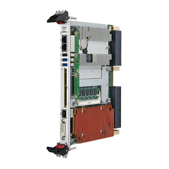
- Page 1 User Manual MIC-6314 OpenVPX 6U CPU Blade with ® ® 4th/5th Gen Intel Xeon E3v4/ Core™ Processor...
- Page 2 No part of this manual may be reproduced, copied, translated, or transmitted in any form or by any means without the prior written permission of Advantech Co., Ltd. The information provided in this manual is intended to be accurate and reliable.
- Page 3 This product has passed the CE test for environmental specifications when shielded cables are used for external wiring. We recommend the use of shielded cables. This type of cable is available from Advantech. Please contact your local supplier for ordering information.
- Page 4 Warnings, Cautions, and Notes Warning! Warnings indicate conditions that if not observed can cause personal injury! Caution! Cautions are included to help prevent hardware damage or data losses. For example, “Batteries are at risk of exploding if incorrectly installed. Do not attempt to recharge, force open, or heat the battery.
- Page 5 The sound pressure level at the operator's position does not exceed 70 dB (A) in accordance with the IEC 704-1:1982 specifications. DISCLAIMER: These instructions are provided according to the IEC 704-1. Advantech disclaims all responsibility for the accuracy of any statements contained herein. MIC-6314 User Manual...
- Page 6 Safety Precaution - Static Electricity Follow these simple precautions to protect yourself from harm and the products from damage. To avoid electrical shock, always disconnect the power from the PC chassis before manual handling. Do not touch any components on the CPU card or other cards while the PC is powered on.
-
Page 7: Table Of Contents
Contents Chapter Hardware Configuration......1 Introduction ....................2 1.1.1 MIC-6314 SKU introduction ............2 Table 1.1: Processor Type ............2 Specifications .................... 3 1.2.1 OpenVPX Interface ............... 3 1.2.2 CPU ....................3 1.2.3 Processor..................3 Table 1.2: Processor Type ............3 1.2.4 BIOS ..................... - Page 8 1.6.3 Ethernet Configuration..............14 1.6.4 SATA Daughter Board Connector (HDD/Extension Module)..14 1.6.5 System Reset and BMC Reset Button........14 Safety Precautions.................. 14 Installation Steps..................15 Figure 1.5 Complete assembly of MIC-6314 convection with the SATA daughter board..........15 Figure 1.6 Complete assembly of MIC-6314 convection with the M.2 daughter board ..........
- Page 9 Table 2.15: SATA Configuration..........40 Figure 2.22NCT6106D HW monitor screen........ 40 2.2.4 Server Management Setup ............41 Figure 2.23Server management configuration screen....41 2.2.5 Boot Setup .................. 42 Figure 2.24Boot configuration screen......... 42 Table 2.16: Boot Configuration............ 42 Figure 2.25Hard disk driver BBS priorities screen...... 43 Table 2.17: Hard Disk Driver BBS Priority Settings.....
- Page 10 3.5.9 Load Default Configuration OEM Command ......65 3.5.10 Swap BIOS Banks OEM Command ........... 66 3.5.11 Graceful Shutdown Timeout OEM Command ......66 UART and UART Multiplexer ..............67 3.6.1 UART Block Diagram..............67 Figure 3.2 UART functional block overview....... 67 ACPI......................
- Page 11 Table A.8: CNSATA1 Daughter Board Connector ..... 91 Table A.9: J15 (P15) Connector ..........91 Table A.10:VCN1 VGA Connector..........92 Table A.11:CNCOM1 (RJ45) Connector........92 Table A.12:CN and CN5 USB Ports 1 and 2 ......92 Table A.13:BT1 CMOS Battery........... 92 Table A.14:RJ1 LAN1 Connector..........
- Page 12 F.2.1 AdvancedTCA (PICMG 3.0 R3.0 Base Specification) ....119 F.2.2 HPM.1 (R1.0)................120 OEM/Group IPMI Commands ............... 120 F.3.1 Advantech OEM Commands ............ 120 Appendix G Drivers and Tools......121 OpenIPMI....................122 IPMItool....................122 MIC-6314 User Manual...
-
Page 13: Chapter 1 Hardware Configuration
Chapter Hardware Configuration This chapter explains how to configure the MIC-6314 hardware. -
Page 14: Introduction
Introduction The MIC-6314 is Advantech’s next generation single processor 6U VPX blade, based on the 4th/ 5th Generation Intel® Core™ embedded platform with increased cache size and efficiency, as well as instruction set improvements. The MIC-6314 provides two configurable PCIE x 8 ports in the VPX data plane and two PCI Express ports x8 lanes in the VPX expansion plane to enable the highest performance available in the 6U VPX form factor compute intense applications. -
Page 15: Specifications
P2 expansion plane. All of these PCIE lanes come from a gen. 3 PCIE switch respectively. Please contact the Advantech representatives for the differ- ent configuration availability. Two lanes of 1GBase-T (can be configured to SerDes upon request) are employed for the P4 control plane. -
Page 16: Chipset
Front I/O (RJ45) Backplane To configure the two P4 lanes of Ethernet to SerDes, contact your local Advantech representative for assistance. 1.2.8 Storage Interface The MIC-6314 supports four ports of SATA III and two SATA II interfaces. A SATA III interface is routed to the SATA connector on the daughter board. -
Page 17: Usb Ports
SKU with IPMI management. Should you require this func- tion in the SKU without IPMI management, please contact your local field service engineer or salesperson. 1.2.13 Optional Rear I/O Modules Please contact your local Advantech representative or distributor for custom RI/O inquires. 1.2.14 Mechanical and Environmental Specifications ... -
Page 18: Pcie Bridge
1.2.16 PCIE Bridge MIC-6314 uses a PLX PEX8733 component, a 32-lane, 8-port, Gen 3 PCIe switch device as a gateway for intelligent subsystems. When configured as a system con- troller, the bridge acts as a standard transparent PCI Express bridge. MIC-6314 receives power from the backplane and supports rear I/O. -
Page 19: Hardware Monitor
An external SPI EEPROM is used for storing field-replaceable unit (FRU) inven- tory data and non-volatile configurations. 1.2.23.1 Key Features Advantech integrity sensor Based on Advantech’s IPMI core and designed for xTCA, CPCI, and VPX Compliant with IPMI 1.5 and IPMI 2.0 specifications IPMI-over-LAN Serial-over-LAN ... -
Page 20: Functional Block Diagram
Functional Block Diagram Power+IPMB PCIe x 8 1600 w/ ECC PCIE switch 8GB DDR3 onboard 1xPCIex16/ 2x PCIex8/ Intel 4x PCIe x4 (NT selectable on one port) Broadwell-H 8GB DDR3 SODIMM 1600 w/ ECC 4/2 Core / GT2 PCIe x 8 PCIE switch ECC/BGA DVIx2... -
Page 21: Board Map
Board Map The location of the main components, jumpers, switches, and thermal sensors is shown in the figure below. PLX_SW2 UARTSW1 UARTSW PLXSW3 PLXSW4 PLX_SW5 I350 PCIE switch PCIE switch RTC Battery FPGA Onboard memory Figure 1.2 Board map Jumpers and Switches Table 1.4 and Table 1.5 list the jumper and switch functions. -
Page 22: Clear Cmos (Cn2)
1.5.1 Clear CMOS (CN2) This jumper is used to erase CMOS data. Follow the procedures below to clear the CMOS: Turn off the system Close jumper CN2 for approximately 3 seconds Set jumper CN2 as Normal Turn on the system. The BIOS is reset to its default settings Table 1.5: CN2 Clear RTC Closed Clear RTC... - Page 23 Table 1.8: PCIe configuration of the Expansion Plane (P2) X8 *2 X4 *4 X16 *1 PLX_SW2 (default) PLX_SW2 PLX_SW2 Table 1.9: PCIe configuration of the Data Plane (P1) X8 *2 X4 *4 X16 *1 PLX_SW5 (default) PLX_SW5 PLX_SW5 Table 1.10: RIO COM RS232/RS485/RS422 Mode Selection COM1 to backplane is set to COM1 to backplane is set to COM1 to backplane is set to...
- Page 24 Table 1.10: RIO COM RS232/RS485/RS422 Mode Selection The COM ports that are routed to the backplane can be configured to three different console modes. The position of the keys must be selected at the correct “ON” orien- tation. BMC can use an OEM command to set the COM port configuration, but the setting will roll back to the FPGA default configuration at every boot up.
-
Page 25: Connector Definitions
Connector Definitions Table 1.13 lists the function of every connector. Figures 1.3 and 1.4 show the location of every connector. Table 1.12: MIC-6314 Connector Description Number Function CNSATA1 SATA HDD daughter board CNDIMM SODIMM socket Figure 1.4 MIC-6314 front panel ports, indicators, and buttons MIC-6314 supports three BMC-controlled front panel LEDs. -
Page 26: Serial Ports
GbE interfaces are routed to the backplane. The two GbE connected to the backplane can be configured to SerDes. Please contact your local Advantech representative to inquire about the availability of the SerDes SKU. 1.6.4 SATA Daughter Board Connector (HDD/Extension Module) MIC-6314 provides one SATA interface via the HDD connector for a daughter card for a CFast card, or optional onboard HDD. - Page 27 The MIC-6314 contains electro-statically sensitive devices. Please discharge your clothing before touching the assembly. Do not touch components or connector pins Advantech recommends that you perform assembly at an anti-static workbench. Figure 1.5 Complete assembly of MIC-6314 convection with the SATA daughter...
- Page 28 Figure 1.6 Complete assembly of MIC-6314 convection with the M.2 daughter board Figure 1.7 Complete assembly of MIC-6314 ruggedized convection with the M.2 daughter board MIC-6314 User Manual...
- Page 29 1750129010 – Battery 3V/210 mAh with wire assembly CR2032M1S8-LF 1.10 Software Support Windows 7 and Red Hat Enterprise Linux have been fully tested on MIC-6314. Please contact your local Advantech sales representative to inquire about support for other operating systems. 1.11 Power consumption The following data provide the maximum continuous current based on Advantech's verification result.
- Page 30 MIC-6314 User Manual...
- Page 31 Chapter AMI APTIO BIOS Setup This chapter describes how to configure the AMI APTIO BIOS (UEFI BIOS).
- Page 32 Introduction ® To extend the features of the Intel Grantley Platform, Advantech has equipped MIC- 6314 with the latest AMI APTIO BIOS for enhanced performance. The UEFI-compliant AMI APTIO BIOS is specifically adapted to MIC-6314 is described in this chapter. With the AMI APTIO BIOS Setup program, users can mod- ify the BIOS settings and control the system’s unique features.
- Page 33 2.2.1 Main Setup Upon first accessing the BIOS Setup Utility, users will enter the Main setup screen. Users can always return to the Main setup screen by selecting the Main tab. Two main setup options are described in this section. The main BIOS setup screen is shown below.
- Page 34 System Date/System Time Use this option to change the system date or time. Highlight System Date or System Time by using the <Arrow> keys. Enter new values via the keyboard. Press the <Tab> key or the <Arrow> keys to move between fields. The date must be entered in MM/DD/YY format.
- Page 35 2.2.2.1 Serial Console Figure 2.4 Serial console settings screen Table 2.3: Serial Console Settings Item Options Description Help Text Console Enabled Enable or disable console redi- Console redirection Redirection Disabled rection. 9600, 19200, 38400, Configure the serial port baud Select the serial port Serial Console 57600, rate.
- Page 36 Table 2.3: Serial Console Settings A parity bit can be sent with the data bits to detect transmission errors. Even: parity bit is 0 if the number of 1s in the data bits is even. Configure if parity bit is generated Odd: parity bit is 0 if None, Even, (transmit data) or checked...
- Page 37 Table 2.3: Serial Console Settings Enable or disable Resolution Enabled Enable or disable extended termi- extended terminal res- 100 x 31 Disabled nal resolution. olution. On legacy OS, the Legacy OS 80x25, number of rows and Redirection Display the terminal size. 80x24 columns support redi- Resolution...
- Page 38 2.2.2.2 USB Configuration Figure 2.5 USB configuration screen Table 2.4: USB Configuration Item Options Description Help Text Disabled Enable or disable USB function USB support parame- USB Support Enabled support ters The Auto option dis- Enable or disable legacy USB ables legacy support if support.
- Page 39 2.2.2.3 Trusted Computing Figure 2.6 Trusted computing screen Table 2.5: Trusted Computing Item Options Description Help Text Enable or disable BIOS support for Enable or disable BIOS support security devices. The for security devices. The OS will OS will not show Security Device Disabled not show security devices.
- Page 40 2.2.2.4 Virtualization Figure 2.7 Virtualization settings screen Table 2.6: Virtualization Item Options Description Help Text Enabling Vanderpool ® Disabled Enable or disable BIOS support Intel Virtualiza- Technology will take Enabled for Vanderpool Technology. tion Technology effect after reboot. Enable or disable ®...
- Page 41 2.2.2.5 Platform Management Figure 2.8 Platform management screen Table 2.7: Platform Management Item Options Description Help Text When enabled, OS sets CPU frequency Enable or disable BIOS support Disabled according load. When ® ® EIST for Enhanced Intel SpeedStep Enabled disabled, CPU fre- Technology quency is set at max...
- Page 42 BMC Self-Test Log Figure 2.9 BMC self-test log screen Table 2.8: BMC Self-Test Log Item Options Description Help Text Yes, on every Decide if the log should be erased Erase Log reset Erase log options. every time the blade reset. Clear Log Select the action to Select the behavior when the log...
- Page 43 System Event log Figure 2.10 System event log screen Table 2.9: System Event Log Item Options Description Help Text Change this to enable Enable or disable all the features Enabled or disable all the fea- SEL Components of system event logging during Disabled tures of system event boot.
- Page 44 2.2.3 Hardware Setup Select the chipset tab from the MIC-6314 setup screen to enter the Hardware setup screen. Users can configure the CPU, northbridge, southbridge, Super IO, and HW monitor parameters. Figure 2.11 Hardware settings screen 2.2.3.1 CPU Configuration Figure 2.12 CPU configuration screen MIC-6314 User Manual...
- Page 45 2.2.3.2 Northbridge Users can configure all the parameters related to the IOH function on the Northbridge setup page. The MIC-6314 BIOS also allows users to configure the PCIe link speed (Gen 1, 2, or 3) and its functions (x16, x8x8, x8x4x4, x4x4x8 or x4x4x4x4) on the IOH configuration submenu.
- Page 46 PCI Express Port Configuration Figure 2.15 PCI Express port configuration screen Table 2.10: PCI Express Port Configuration Item Options Description Help Text Auto Configure PEG0/1/2 PEG0/PEG1/ Gen1 Access PEG0/1/2 link and speed B0:D1:F0 Gen1- PEG2 Gen2 information. Gen3. Gen3 Auto Enable or disable Enable PEG...
- Page 47 PCI Subsystem Settings Figure 2.16 PCI subsystem setting screen Table 2.11: PCI Subsystem Settings Item Options Description Help Text 32 PCI Bus Clocks 64 PCI Bus Clocks 96 PCI Bus Clocks 128 PCI Bus Sets the value to be Clocks Sets the value to be programmed programmed into the...
- Page 48 Table 2.11: PCI Subsystem Settings 32 PCI Bus Clocks 64 PCI Bus Clocks 96 PCI Bus Clocks 128 PCI Bus Sets the value to be PCI-X Latency Clocks Sets the value to be programmed programmed into the Timer 160 PCI Bus into the PCI latency timer register.
- Page 49 2.2.3.3 Southbridge Users can configure all the parameters related to PCH function on the Southbridge setup page. Figure 2.17 Southbridge configuration screen SATA Configuration Figure 2.18 SATA configuration screen MIC-6314 User Manual...
- Page 50 Table 2.12: SATA Configuration Item Options Description Help Text Disabled Enable or disable the SATA con- Enable or disable the SATA Controller Enabled troller. SATA controller. AHCI Configure SATA as SATA Mode Configure SATA as IDE or AHCI. IDE or AHCI. ...
- Page 51 2.2.3.4 NCT6106D Super IO Configuration Users can configure the serial port parameters related to the NCT6104D Super IO. Figure 2.20 NCT6106D Super IO configuration screen Serial Port 1/2/3/4 Configuration Figure 2.21 Serial port 1/2/3/4 configuration screen MIC-6314 User Manual...
- Page 52 Table 2.14: Serial Port 1/2/3/4 Configuration Item Options Description Help Text Disabled Enable or disable serial ports Enable or disable serial Serial Port Enabled (COM). ports (COM). Enable or disable the Auto Auto Flow Control Auto Flow Control Flow Control of RS485 mode Table 2.15: SATA Configuration Item Options...
-
Page 53: Server Management Setup
2.2.4 Server Management Setup The server management setup menu features BMC-related items, such as the OS Watchdog Timer. To obtain details of the BMC self-test log and system event log, users can enable the function to record logs. Alternatively users can erase logs via the BMC self-test log submenu or the system event log submenu. -
Page 54: Boot Setup
2.2.5 Boot Setup The Post and Boot menu allows users to configure POST behavior and boot options. Figure 2.24 Boot configuration screen Table 2.16: Boot Configuration Item Options Description Help Text Number of seconds to Number of seconds to wait for wait for the setup acti- Setup Prompt 1 to 65535... - Page 55 Drive types appear in the boot device priority menu even if no drives are present (i.e., the drives are not yet connected). The Boot Device Priority submenu (boot sources) and “xxx Boot Device” submenus are always available even when no device is present in the corresponding boot device submenu.
- Page 56 2.2.5.1 CSM16 Parameters Figure 2.26 CSM16 parameters screen Table 2.18: CSM16 Parameters Item Options Description Help Text This item is useful when RT code is executed above 1MB. When this is Enable or disable the set as "Upon Request", Upon Request addressing bus from GateA20 Active GA20 can be disabled...
- Page 57 2.2.5.2 CSM Parameters Figure 2.27 CSM parameters screen Table 2.19: CSM Parameters Item Options Description Help Text Disabled Enable or disable CSM Enable or disable CSM CSM Support Enabled support. support. UEFI and Legacy This option controls This option controls leg- Boot Option Filter UEFI only legacy/UEFI ROM pri-...
-
Page 58: Security Setup
2.2.6 Security Setup The Security page items allow users to enable password protection and set access passwords. Two password levels are provided: Administrator and User. When log- ging in at Administrator level, all configuration parameters can be modified. At the User privilege level, certain parameters cannot be changed and certain actions can- not be performed, as specified below. -
Page 59: Save & Exit Options
2.2.7 Save & Exit Options The Save & Exit page provides various options for exiting the setup menu and restor- ing the default values for all configuration parameters. Figure 2.29 Save & Exit configuration screen Table 2.20: Save & Exit Configuration Item Options Description... - Page 60 Table 2.20: Save & Exit Configuration Restore/load the default Load the factory default Restore Defaults settings for all setup settings. options. Save as User Save all changes as Save all changes as user Defaults user defaults. defaults. Restore the setup Restore User Defaults options to the settings Restore the user defaults...
-
Page 61: Chapter 3 Bmc Firmware Operation
Chapter BMC Firmware Operation This chapter describes the BMC firmware features. -
Page 62: Module Management
Module Management The IPMI Baseboard Management Controller (BMC) located on MIC-6314 acts as a standard IPMI management controller and is an essential part of the board. The BMC’s primary tasks are to ensure module health (monitoring the voltage and tem- perature sensors), facilitate payload state management and information data storage, and provide IPMI communication interfaces. -
Page 63: Lan
All important voltages and temperatures are connected to the BMC sensor. The BMC management subsystem also monitors the following logical sensors: BMC Watchdog sensor FW Progress sensor Version change sensor Processor sensors (processor hot, thermal trip, etc.) Advantech OEM sensor: integrity sensor MIC-6314 User Manual... -
Page 64: Sensor List
IPMI FW Progress sensor Progress (Discrete) Version Change VERSION_CHANGE IPMI Version Change sensor (Discrete) PROC_VR_HOT OEM (Discrete) Advantech OEM Processor HOT status THERM_TRIP OEM (Discrete) Advantech OEM CPU Thermal Trip INTEGRITY OEM (Discrete) Advantech OEM Integrity sensor PAY_12_0-VOL Voltage (Threshold) -
Page 65: Threshold-Based Sensors
3.3.2 Threshold-Based Sensors According to the IPMI specification, sensor event thresholds are classified as Non- Critical, Critical, or Non-Recoverable. When various thresholds are reached, different actions may be executed by the carrier or shelf manager (e.g., fan speed adjustment for temperature sensor events). The table below lists the six thresholds specified for the threshold-based sensors described in the following sections. -
Page 66: Discrete Sensors
3.3.2.2 Temperature Sensors MIC-6314 supports temperature sensors via either board-populated ICs (e.g., TMP75) or readings from the CPU/chipset interfaces (PECI/SMBus). Table 3.4: Temperature Sensor List Sensor Name Value CPU-TMP HDD-TMP SYS-TMP LAN_BI-TMP 3.3.3 Discrete Sensors 3.3.3.1 BMC Device Locator Every BMC provides a PICMG compliant FRU device locator for the subsystem. This record is used to maintain the BMC location and type information. -
Page 67: Example Sensor Data
3.3.3.7 Thermal Trip Sensor To monitor the CPU thermal trip states via the FPGA, the BMC features a discrete OEM sensor. The underlying bitmasks for identifying these events are shown in the table below. Table 3.7: Thermal Trip Sensor Bits Description Therm Trip CPU 0 3.3.4... -
Page 68: Integrity Sensor
3.3.5.1 Overview The Advantech integrity sensor is an OEM sensor that accords with the sensor data record (SDR) definition in the IPMI specification. The main purpose of the integrity sensor is to monitor internal firmware states and report events that would otherwise go unnoticed to the operator (hence “integrity sensor”). - Page 69 Event data 3 [2..0] holds the result code. For the HPM.1 example above, the data may report that an update or rollback succeeded or failed. For the FRU example, the data may indicate a checksum error. 3.3.5.3 Event Data Byte Definition The integrity sensor event byte definitions are listed in the table below.
- Page 70 3.3.5.5 Event Data Table All event data combinations supported by the BMC integrity sensor are listed in the table below. Table 3.9: Integrity Sensor Event Data Component Action / Subcomponent Result Byte 1 Byte2 Update Successful 0x01 0x00 Update Timeout 0x01 0x04 Update...
- Page 71 [root@localhost ~]# ipmitool sel get 0x684 SEL Record ID : 0684 Record Type : 02 Timestamp : 07/15/2016 18:49:19 Generator ID : 008e EvM Revision : 04 Sensor Type : OEM Sensor Number : 06 Event Type : Sensor-specific Discrete Event Direction : Assertion Event Event Data (RAW)
-
Page 72: Fru Information
More precisely, the vendor IANA Enterprise Number for the defining body occupies the first three data bytes in a request, and the first three data bytes following the com- pletion code position in a response. Advantech’s IANA Enterprise Number used for OEM commands is 002839h. -
Page 73: Ipmitool Raw Command
3.5.1 IPMItool Raw Command To use Advantech OEM commands with the open source IPMItool, users must employ the “raw” command of IPMItool. The structure of the IPMItool raw command is detailed below. General raw request: ipmitool raw <netfn> <cmd> [data] Response, if raw <netfn>... -
Page 74: Fpga Com Port Uart Mux
UART MUX (refer to Section 3.6 – UART and UART Multiplexer). The BMC provides OEM commands for configuring UARTs via IPMI. The available COM1 and COM2 port settings are shown below (Advantech recommends that you verify the UART dependency.). - Page 75 COM1 MUX: Table 3.12: COM1 UART MUX Settings Setting Connection 0x00 No interface connected, open 0x01 Serial over LAN (SOL) 0x02 Front panel RJ45 0x03 RTM 1 0x04 RTM 2 COM2 MUX: Table 3.13: COM2 UART MUX Settings Setting Connection 0x00 No interface connected, open 0x01...
-
Page 76: Bmc Uart (Cli) Baud Rate Oem Command
3.5.5 BMC UART (CLI) Baud Rate OEM Command Users can change the baud rate of the BMC UART via the COM port. Read the BMC UART baud rate setting: ipmitool raw 0x2e 0x41 0x39 0x28 0x00 0x0c 0x00 Response: 39 28 00 <setting> Change the BMC UART baud rate setting: ipmitool raw 0x2e 0x40 0x39 0x28 0x00 0x0c 0x00 <setting>... -
Page 77: Read Port 80 (Bios Post Code) Oem Command
3.5.7 Read Port 80 (BIOS POST Code) OEM Command To read the actual BIOS boot state via IPMI, the BMC provides an Advantech OEM command to reflect the actual BIOS POST (Port 80) code. ipmitool raw 0x2e 0x80 0x39 0x28 0x00 Response: 39 28 00 <POST Code>... -
Page 78: Swap Bios Banks Oem Command
3.5.10 Swap BIOS Banks OEM Command The board features two BIOS banks, one for active BIOS and the other for redun- dancy. Users can swap the BIOS banks manually using the OEM command shown below. Note that the BIOS banks can only be swapped when the payload power is turned off. -
Page 79: Uart And Uart Multiplexer
UART and UART Multiplexer 3.6.1 UART Block Diagram Figure 3.2 UART functional block overview ACPI 3.7.1 ACPI-Featured Graceful Shutdown Note! The payload OS used with MIC-6314 must support ACPI to enable the module graceful shutdown feature. If a shutdown request is sent (via a hot-swap front panel handle “open” event or an IPMI command), the BMC will initiate OS shutdown via the ACPI power button signal routed to the x86 system. -
Page 80: Bios Failover/Redundancy
BIOS Failover/Redundancy 3.8.1 Overview MIC-6314 supports BIOS redundancy via the BMC. Two BIOS SPI flashes are pro- vided on the board. This BIOS redundancy mechanism is responsible for managing flash failover in the event that the selected BIOS fails to boot. This could happen if, for example, a BIOS update over HPM.1 was performed and the new BIOS version does not boot. -
Page 81: Resets
3.10 Resets Several reset types are support by the board. This section provides an overview of the naming and differences between the available resets. 3.10.1 Baseboard Management Controller Resets The MIC-6314 BMC supports two resets types: cold and warm resets, according to the IPMI specification. -
Page 82: Serial Over Lan Setup
Following default parameters are ideal for the initial MIC-6314 LAN setup: IP-Address: 0.0.0.0 LAN Channel Number: 5 Username: "administrator" Password: "advantech" 3.11.2 LAN Configuration with IPMItool The open source IPMItool utility is used for MIC-6314 SOL and LAN parameter con- figuration. - Page 83 3.11.2.1 LAN Commands lan print [channel number] This command can be used to obtain the LAN configuration parameters for a given channel. [root@localhost ~]# ipmitool lan print Set in Progress : Set Complete Auth Type Support : NONE MD5 PASSWORD Auth Type Enable : Callback : NONE MD5 PASSWORD : User...
-
Page 84: Sol Session With Ipmitool
3.11.3 SOL Session with IPMItool Advantech recommends using IPMItool to successful open a SOL session with MIC- 6314. The “lanplus” interface (RMCP+) of IPMItool is required to change the SOL parameters and establish SOL sessions. The following general IPMItool parameters are required for RMCP+ and IPMItool “sol”... - Page 85 sol set <parameter> <value> [channel] This command can be used to modify specific SOL configuration parameters. # ipmitool -I lanplus <BMC IP-Address> -U <User> -P <Password> sol set SOL set parameters and values: set-in-progress set-complete | set-in-progress | commit-write enabled true | false force-encryption...
- Page 86 MIC-6314 User Manual...
-
Page 87: Hpm.1 Update
Chapter HPM.1 Update This chapter explains how to update the software/firmware components. -
Page 88: Hpm.1 Preconditions
HPM.1 Preconditions 4.1.1 IPMItool Before upgrading, users must prepare a HPM.1-capable update utility. Advantech recommends using the open and verified “IPMItool” (>= version 1.8.10). Generally, any tool that complies with the PICMG HPM.1 R1.0 specification can be used. 4.1.2 Interfaces HPM.1 provides a means to upgrade firmware using various interfaces... -
Page 89: Bmc Bootloader Upgrade
BMC Bootloader Upgrade 4.2.1 Load New BMC Bootloader Image Input the IPMItool HPM.1 upgrade command and select the new BMC bootloader image. [root@localhost ~]# ipmitool hpm upgrade mic6313_bootloader_standard_0x01_ 0x01_adv.img PICMG HPM.1 Upgrade Agent 1.0.9: Validating firmware image integrity...OK Performing preparation stage... Services may be affected during upgrade. -
Page 90: Bmc Firmware Upgrade
BMC Firmware Upgrade 4.3.1 Load New BMC Firmware Image Input the IPMItool HPM.1 upgrade command and select the new BMC firmware image. [root@localhost ~]# ipmitool hpm upgrade mic6313_standard_hpm_fw_01_01.img PICMG HPM.1 Upgrade Agent 1.0.9: Validating firmware image integrity...OK Performing preparation stage... Services may be affected during upgrade. -
Page 91: Fpga Configuration Upgrade
FPGA configuration upgrade 4.4.1 Load new FPGA image Type IPMItool HPM.1 upgrade command and select the new FPGA image. [root@localhost ~]# ipmitool hpm upgrade mic6313_fpga_standard_01_14.img PICMG HPM.1 Upgrade Agent 1.0.9: Validating firmware image integrity...OK Performing preparation stage... Services may be affected during upgrade. Do you wish to con- tinue? (y/n): y Performing upgrade stage: -------------------------------------------------------------... -
Page 92: Bios Upgrade
4.4.2.2 Payload Cold Reset To activate the new FPGA image a payload cold reset is required. (*) Component requires Payload Cold Reset The payload reset can be performed using either of the following methods: For users working on the local OS (KCS), a linux “reboot”, “power off”, or “halt” operation is required. -
Page 93: Activate Bios Image
4.5.2 Activate BIOS Image After the new BIOS image is successfully loaded (known as the “deferred” version), the image must be activated to enable booting of the new BIOS. Perform the follow- ing two actions to activate the BIOS image and complete the upgrade. 4.5.2.1 HPM.1 Activate Command Schedule BIOS loading using the HPM.1 activate command: shown below. -
Page 94: Verify Successful Upgrades
[root@localhost ~]# ipmitool hpm check PICMG HPM.1 Upgrade Agent 1.0.9: -------Target Information------- Device Id : 0x74 Device Revision : 0x81 Product Id : 0x6313 Manufacturer Id : 0x2839 (Advantech) ------------------------------------------------------------- ------------- | Name Ver- sions Active Backup Deferred ------------------------------------------------------------- ------------- 0|6313 BL 1.01 00000000 | ---.-- -------- | ---.-... -
Page 95: Appendix A Pin Assignments
Appendix Pin Assignments This appendix describes the pin assignments. -
Page 96: P0 Connector
P0 Connector Table A.1: P0 VPX I/O +12V +12V +12V +12V +12V +12V +12V +12V +12V +12V +12V +12V IPMB0- IPMB0- -12V_AUX SYSRESET NVMRO B_CLK B_DAT 3.3V_AUX IPMB0- IPMB0- (not used) A_CLK A_DAT PLX_REFCL PLX_REFCL Note! NC = No Connection # = Active Low MIC-6314 User Manual... -
Page 97: P1 Connector
P1 Connector P1 connector is Data Plane (DP) that can Support PCIE X16 lane, default setting is 2port X8 can configure to 1port X16 or 4port X4. Table A.2: P1 VPX I/O PCIE_P1_ PCIE_P1_TX PCIE_P1_RX PCIE_P1_R TX0- PCIE_P1_T PCIE_P1_ PCIE_P1_R PCIE_P1_RX TX1+ +VBAT_RI... -
Page 98: P2 Connector
P2 Connector The P2 connector supports two PCIE ports, with eight lanes per port. This can also be configured as four 4-lane ports or one 16-lane port. Six GPIO pins are reserved and can be defined by the user. Table A.3: P2: I/O HDDErase PCIE_P1_T PCIE_P1_TX... -
Page 99: P3 Connector (Reserved)
P3 Connector (Reserved) Table A.4: P3 VPX I/O Wafer Offset Row G Row F Row E Row D Row C Row B Row A Jn4-1 Jn4-3 Jn4-2 Jn4-4 Jn4-5 Jn4-7 Jn4-6 Jn4-8 Jn4-9 Jn4-11 Jn4-10 Jn4-12 Jn4-13 Jn4-15 Jn4-14 Jn4-16 Jn4-17 Jn4-19 Jn4-18... -
Page 100: P4 Connector
P4 Connector The P4 connector supports an XMC card (X8d+X12d). Three GPIO pins are reserved and can be defined by the user. Two 1G Base-T ports are provided and can be configured to two SerDes ports (optional). Table A.5: P4 VPX I/O RIO_SATA_L Jn6-A5 Jn6-B5... -
Page 101: P5 Connector
P5 Connector The P5 connector supports two DVI ports, one VGA port, two USB 3.0 ports, three Gen 3 SATA ports, and two UART ports. Table A.6: P5 VPX I/O DP2_HPD DVI2_D1- DVI2_D1+ DVI2_D2- DVI2_D2+ DVI2_CLK- DVI2_CLK+ GND DVI2_D0- DVI2_D0+ DP1_HPD DVI1_D1- DVI 1_D1+... -
Page 102: P6 Connector
P6 Connector The P6 connector supports two 1G Base-T ports, five USB 2.0 ports, one Gen 2 SATA port, two UART ports, one PS2 keyboard/ mouse port, one Line In/Out, and one microphone port. Four GPIO pins are reserved and can be defined by the user. Table A.7: P6 VPX I/O VGA_DCLK USB6-... -
Page 103: Additional Connectors
Additional Connectors Table A.8: CNSATA1 Daughter Board Connector SATA0_TX+ SATA0_TX- SATA0_RX+ SATA0_RX- VCC5 VCC3 VCC5 VCC3 Table A.9: J15 (P15) Connector PETX_P0 PETX_N0 +3.3V PETX_P1 PETX_N1 VPWR(+5V) NC(JRST#) PRST# PETX_P2 PETX_N2 +3.3V PETX_P3 PETX_N3 VPWR(+5V) NC(JTCK) (MRSTO#) PETX_P4 PETX_N4 +3.3V PETX_P5 PETX_N5 VPWR(+5V) - Page 104 Table A.10: VCN1 VGA Connector GREEN BLUE DDC_DATA HSYNC VSYNC DDC_CLK Table A.11: CNCOM1 (RJ45) Connector DCD# DSR# RTS# SOUT CTS# DTR# Table A.12: CN and CN5 USB Ports 1 and 2 +5V (fused) +5V (fused) USBD0- USBD1- USBD0+ USBD1+ Table A.13: BT1 CMOS Battery BAT_VCC Table A.14: RJ1 LAN1 Connector...
-
Page 105: M/D, Pwr, Bmc Hb, And Ide/Hot-Swap Leds
A.8.1 M/D, PWR, BMC HB, and IDE/Hot-Swap LEDs Name Description PWR (Green) Indicates power status BMC (Yellow) Indicates BMC status (steady blinking indicates the BMC is active) HDD/Hot Swap Indicates IDE activity when yellow, and that the board is ready to (Yellow/Blue) be hot-swapped when blue. - Page 106 MIC-6314 User Manual...
-
Page 107: Appendix B Programming The Watchdog Timer
Appendix Programming the Watchdog Timer This appendix describes how to program the watchdog timer. -
Page 108: Watchdog Timer Programming Procedure
Watchdog Timer Programming Procedure To program the watchdog timer, users must execute a program that writes a value to I/O port address 443/444 (hex) to enable/disable. This output value represents a time interval. The value range is from 01 (hex) to FF (hex), and the related time interval is 1 to 255 seconds. -
Page 109: Appendix C I/O Controller List
Appendix I/O Controller List... -
Page 110: I/O Controller List
I/O Controller List I/O Port Controller DVI to backplane Intel Broadwell Intel Lynx Point Onboard flash Intel Lynx Point SATA Intel Lynx Point SATA to backplane Intel Lynx Point Cfast Intel Lynx Point USB 2.0/3.0 to front panel Intel Lynx Point USB 2.0/3.0 to backplane Intel Lynx Point Audio to backplane... -
Page 111: Appendix D Glossary
Appendix Glossary... -
Page 112: Glossary
Glossary ACPI Advanced Configuration and Power Interface Baseboard Management Controller Central Processing Unit CPCI CompactPCI Direct Memory Access DRAM Dynamic Random Access Memory Error Checking and Correction EEPROM Electrically Erasable Programmable Read-Only Memory Electro Magnetic Compatibility Electro Static Discharge FCBGA Flip Chip BGA Hard Disk Drive HardwareManagement... - Page 113 RMCP Remote Management Control Protocol Sensor Data Record SerDes Serializer/Deserializer Serial Over LAN Serial Peripheral Interface UART Universal Asynchronous Receiver Transmitter MIC-6314 User Manual...
- Page 114 MIC-6314 User Manual...
-
Page 115: Appendix Ebios Checkpoint
Appendix BIOS Checkpoint... -
Page 116: Checkpoint Ranges/Descriptions
A status code is a data value used to indicate progress during the boot phase. A sub- set of these status codes, known commonly as checkpoints, indicates common phases of the BIOS boot process. Checkpoints are typically output to I/O port 80h, but the Aptio 4.x core can be config- ured to send status codes to various locations. -
Page 117: Standard Checkpoints
Standard Checkpoints E.2.1 SEC Phase Status Code Description 0x00 Not used Progress Codes 0x01 Power on. Reset type detection (soft/hard). 0x02 AP initialization before microcode loading 0x03 Northbridge initialization before microcode loading 0x04 Southbridge initialization before microcode loading 0x05 OEM initialization before microcode loading 0x06 Microcode loading 0x07... - Page 118 0x2B Memory initialization. Serial presence detect (SPD) data reading 0x2C Memory initialization. Memory presence detection 0x2D Memory initialization. Programming memory timing information 0x2E Memory initialization. Configuring memory 0x2F Memory initialization (other). 0x30 Reserved for ASL (see the ASL status codes section below) 0x31 Memory installed 0x32...
-
Page 119: Dxe Phase
0xE2 Video repost 0xE3 OS S3 wake vector call 0xE4-0xE7 Reserved for future AMI progress codes S3 Resume Error Codes 0xE8 S3 resume failed 0xE9 S3 resume PPI not found 0xEA S3 resume boot script error 0xEB S3 OS wake error 0xEC-0xEF Reserved for future AMI error codes Recovery Progress Codes... - Page 120 0x75 Southbridge DXE Initialization (Southbridge module specific) 0x76 Southbridge DXE Initialization (Southbridge module specific) 0x77 Southbridge DXE Initialization (Southbridge module specific) 0x78 ACPI module initialization 0x79 CSM initialization 0x7A – 0x7F Reserved for future AMI DXE codes 0x80 – 0x8F OEM DXE initialization codes 0x90 Boot device selection (BDS) phase is started...
-
Page 121: Acpi/Asl Checkpoints
DXE Error Codes 0xD0 CPU initialization error 0xD1 Northbridge initialization error 0xD2 Southbridge initialization error 0xD3 Some architectural protocols are not available 0xD4 PCI resource allocation error. Out of resources 0xD5 No space for legacy option ROM 0xD6 No console output devices are found 0xD7 No console input devices are found 0xD8... - Page 122 MIC-6314 User Manual...
-
Page 123: Ipmi/Picmg Command Subset
Appendix IPMI/PICMG Command Subset Supported by... -
Page 124: Standard Ipmi Commands (V2.0)
Standard IPMI Commands (v2.0) F.1.1 IPM Device Global Commands IPMI v2.0 Advantech Command NetFn IPMI BMC Req. Ref. BMC Support Get Device ID 20.1 Mandatory Cold Reset 20.2 Optional Warm Reset 20.3 Optional Get Self Test Results 20.4 Mandatory Manufacturing Test On 20.5... - Page 125 Activate Session 22.17 Optional Set Session Privilege Level 22.18 Optional Close Session 22.19 Optional Get Session Info 22.20 Optional Get AuthCode 22.21 Optional Set Channel Access 22.22 Optional Get Channel Access 22.23 Optional Get Channel Info 22.24 Optional Set User Access 22.26 Optional Get User Access...
-
Page 126: Chassis Device Commands
F.1.4 Chassis Device Commands Advantech IPMI v2.0 Command NetFn IPMI BMC Req. Ref. Support Get Chassis Capabilities 28.1 Chassis 00h Mandatory Optional/ Get Chassis Status 28.2 Chassis 01h Mandatory Optional/ Chassis Control 28.3 Chassis 02h Mandatory Chassis Reset 28.4 Chassis 03h... -
Page 127: Sensor Device Commands
F.1.7 Sensor Device Commands IPMI v2.0 Advantech Command NetFn IPMI BMC Req. Ref. BMC Support Get Device SDR Info 35.2 Optional Get Device SDR 35.3 Optional Reserve Device SDR 35.4 Optional Repository Get Sensor Reading 35.5 Optional Factors Set Sensor Hysteresis 35.6... -
Page 128: Sel Device Commands
33.20 Storage 2Bh Mandatory Update Mode Run Initialization Agent 33.21 Storage 2Ch Optional F.1.10 SEL Device Commands IPMI v2.0 Advantech Command NetFn IPMI BMC Req. Ref. BMC Support Get SEL Info 31.2 Storage 40h Mandatory Get SEL Allocation Info 31.3... -
Page 129: Bridge Management Commands (Icmb)
Transport 20h Set SOL Configuration 26.2 Transport 21h Parameters Get SOL Configuration 26.3 Transport 22h Parameters F.1.13 Bridge Management Commands (ICMB) IPMI v2.0 Advantech Command NetFn IPMI BMC Req. Ref. BMC Support Optional/ Get Bridge State [ICMB] Bridge Mandatory Optional/... -
Page 130: Discovery Commands (Icmb)
F.1.14 Discovery Commands (ICMB) IPMI v2.0 Advantech Command NetFn IPMI BMC Req. Ref. BMC Support Optional/ Prepare For Discovery [ICMB] Bridge Mandatory Optional/ Get Addresses [ICMB] Bridge Mandatory Optional/ Set Discovered [ICMB] Bridge Mandatory Optional/ Get Chassis Device ID [ICMB]... -
Page 131: Other Bridge Commands
F.1.18 Other Bridge Commands Advantech IPMI v2.0 IPMI BMC Command NetFn Ref. Req. Support Optional/ Error Report [ICMB] Bridge Mandatory PICMG IPMI Commands F.2.1 AdvancedTCA (PICMG 3.0 R3.0 Base Specification) PICMG IPMI BMC Advantech Command NetFn 3.0 Table Req. BMC Support... -
Page 132: Hpm.1 (R1.0)
PICMG Query Self-test Results 3-12 PICMG Query Rollback status 3-13 PICMG Initiate Manual Rollback 3-14 PICMG OEM/Group IPMI Commands F.3.1 Advantech OEM Commands IPMI BMC Advantech BMC Command NetFn Req. Support OEM/ Store Configuration Settings Group OEM/ Read Configuration Settings... -
Page 133: Appendix G Drivers And Tools
Appendix Drivers and Tools... -
Page 134: Openipmi
OpenIPMI The OpenIPMI project provides an IPMI kernel driver that is available in most Linux distributions. The Open IPMI Linux device driver is designed as a fully functional IPMI device driver with the following features: Allows multiple users Allows multiple interfaces ... - Page 135 MIC-6314 User Manual...
- Page 136 No part of this publication may be reproduced in any form or by any means, such as electronically, by photocopying, recording, or otherwise, without prior written permission from the publisher. All brand and product names are trademarks or registered trademarks of their respective companies. © Advantech Co., Ltd. 2019...
Need help?
Do you have a question about the MIC-6314 Series and is the answer not in the manual?
Questions and answers