
Related Manuals for Pololu Romi 32U4


Summary of Contents for Pololu Romi 32U4
- Page 1 Pololu Romi 32U4 Control Board User’s Guide © 2001–2019 Pololu Corporation Pololu Romi 32U4 Control Board User’s Guide https://www.pololu.com/docs/0J69/all Page 1 of 55...
-
Page 2: Table Of Contents
7. The Romi 32U4 USB interface ........ -
Page 3: Overview
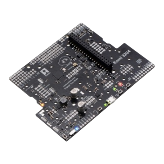
LCD allow the robot to provide feedback. The Romi 32U4 Control Board can be used either as a standalone control solution or as a base for a more powerful Raspberry Pi controller. Its on-board connector and mounting holes allow a compatible... -
Page 4: What You Will Need
Raspberry Pi An LCD and Raspberry Pi are not included with the Romi 32U4 Control Board. 1.2. What you will need These additional items are also needed for using and assembling the Romi 32U4 Control Board: Required accessories • a... -
Page 5: Supported Operating Systems
[https://www.pololu.com/product/2588] 1.3. Supported operating systems The Romi 32U4 Control Board can be programmed using any operating system that supports the Arduino environment. This includes Microsoft Windows 10, 8.1, 8, 7, Vista, XP (with Service Pack 3), Linux, and macOS. -
Page 6: Contacting Pololu
Pololu Romi 32U4 Control Board User’s Guide © 2001–2019 Pololu Corporation 2. Contacting Pololu We would be delighted to hear from you about any of your projects and about your experience with the Romi 32U4 Control Board. You can contact us directly or post on our [https://www.pololu.com/contact]... -
Page 7: Romi 32U4 Control Board
, which allows it to be easily programmed using the [https://www.pololu.com/docs/0J66/7] Arduino IDE. For more information about programming the Romi 32U4 Control Board, see Section The board also has a 6-pin ISP header that allows it to be programmed with an external programmer,... - Page 8 The functions in the Romi32U4 library take care of configuring the pins, reading and debouncing the buttons, and restoring the pins to their original states. The Romi 32U4 Control Board has a set of through-holes in the center where a 2×7 header can be soldered to connect an 8×2 character LCD...
-
Page 9: Motor Drivers And Encoders
3.3. Motor drivers and encoders Motor drivers The Romi 32U4 Control Board has two Texas Instruments DRV8838 motor drivers that are used to power the Romi chassis’s two mini plastic gearmotors . - Page 10 . A pair of low-profile female headers is [https://www.pololu.com/product/3542] included with the Romi 32U4 Control Board and can be soldered into either the outer or inner row of through-holes on each side. (Note that these headers must be soldered into the positions that match the male header installed on the encoder board.)
-
Page 11: Inertial Sensors
Section 3.4. Inertial sensors The Romi 32U4 Control Board includes on-board inertial sensors connected to the ATmega32U4’s I²C interface that can be used in advanced applications, such as helping detect collisions and determining the robot’s orientation. These sensors are part of the ST LSM6DS33 [https://www.pololu.com/product/... -
Page 12: Power
3.5. Power The Romi 32U4 Control Board includes battery terminal connections that provide access to power from the Romi chassis’s six-AA battery compartment. We recommend using rechargeable AA NiMH cells, which results in a nominal voltage of 7.2 V (1.2 V per cell). You can also use alkaline cells, which would nominally give you 9 V. - Page 13 Pololu Romi 32U4 Control Board User’s Guide © 2001–2019 Pololu Corporation controlled with the on-board pushbutton. By default, this pushbutton can be used to toggle power: one push turns on power and another turns it off. Alternatively, a separate pushbutton can be connected to the PWRA and PWRB pins and used instead.
- Page 14 Pololu Romi 32U4 Control Board User’s Guide © 2001–2019 Pololu Corporation Description Connect through momentary switch to pin “PWRB” for standard push-on/push-off PWRA operation. Connect through momentary switch to ground for on-only operation. Connect through momentary switch to pin “PWRA” for standard push-on/push-off PWRB operation.
- Page 15 The Romi 32U4 Control Board also contains a 3.3 V LDO that draws its power from the output of the logic power selection circuit described below. The output of the 3.3 V regulator is designated 3V3 and is used to supply the on-board inertial sensors and level shifters.
-
Page 16: Expansion Areas
3.6. Expansion areas The Romi 32U4 Control Board has several expansion areas (primarily in three groups near the front left and middle and back right edges) that break out all of the general-purpose I/O lines from the ATmega32U4 microcontroller and the Raspberry Pi. - Page 17 Pololu Romi 32U4 Control Board User’s Guide © 2001–2019 Pololu Corporation Pinout diagram of the Romi 32U4 Control Board (ATmega32U4 pinout, peripherals, and board power control). 3. Romi 32U4 Control Board Page 17 of 55...
- Page 18 Pololu Romi 32U4 Control Board User’s Guide © 2001–2019 Pololu Corporation Pinout diagram of the Romi 32U4 Control Board (Raspberry Pi pinout, peripherals, and level shifters). 3. Romi 32U4 Control Board Page 18 of 55...
-
Page 19: Raspberry Pi Interface And Level Shifters
Power distribution diagram of the Romi 32U4 Control Board. 3.7. Raspberry Pi interface and level shifters The Romi 32U4 Control Board was designed to be easy to interface with a Raspberry Pi single- board computer to expand the Romi’s processing power. It has a connector and mounting holes... - Page 20 [https://www.pololu.com/product/3119] Raspberry Pi and Raspberry Pi slave library for Arduino still apply for the Romi 32U4 Control Board, and we will be releasing an updated tutorial with steps specific to the Romi soon.
- Page 21 Pololu Romi 32U4 Control Board User’s Guide © 2001–2019 Pololu Corporation Raspberry Pi robot using the A-Star 32U4 Robot Controller. General-purpose level shifters In addition to the dedicated I²C level shifters, the board also makes available a few general-purpose level shifters that are not connected to any signals by default.
-
Page 22: Pin Assignments
The table below lists the most important pin assignments for the ATmega32U4 on the Romi 32U4 Control Board. This table is helpful if you want to add your own electronics to the Romi 32U4, write your own low-level code for interfacing with the hardware, or just want to understand better how the Romi 32U4 works. - Page 23 4. Also, due to hardware limitations, some functions only work on a limited set of pins. The “Romi 32U4 functions” column documents what the pin is used for on the Romi 32U4 Control Board. Many pins can serve multiple purposes concurrently by switching modes. For example, PB0 can read the state of button C when it is an input, and it can control the red LED and serve as an LCD data line when it is an output.
- Page 24 Pololu Romi 32U4 Control Board User’s Guide © 2001–2019 Pololu Corporation ATmega32U4 Arduino Romi 32U4 Control Board Notes/alternate functions pin name pin names functions Timer0 PWM output A (OC0A) Timer1 PWM output C LCD control line (E) (OC1C) UART flow control (RTS)
- Page 25 Pololu Romi 32U4 Control Board User’s Guide © 2001–2019 Pololu Corporation ATmega32U4 Arduino Romi 32U4 Control Board Notes/alternate functions pin name pin names functions Timer1 PWM output B (OC1B) Timer4 PWM output B (OC4B) Pin-change interrupt (PCINT6) SPI Master Output/Slave...
-
Page 26: Adding Electronics
Analog input (ADC1) internally pulled high, active RESET Reset pushbutton AREF Analog reference 3.9. Adding electronics This section gives tips for how additional electronics can be connected to the Romi 32U4 Control Board. 3. Romi 32U4 Control Board Page 26 of 55... - Page 27 If the free I/O pins are not sufficient for connecting the devices you want to connect, you might need to disable or disconnect some of the other features of the Romi 32U4 Control Board to free up more I/ O pins.
- Page 28 Be careful about connecting electronics to pin 13 (PC7), pin 17 (PB0), and pin 30 (PD5). These pins are used to control the LEDs on the Romi 32U4. All three of these pins are controlled as outputs by the bootloader. Pin 17 (PB0) and pin 30 (PD5) are used as RX and TX indicators, so if you are sending or receiving data over USB then the Arduino USB code will drive those pins in its interrupt service routines while your sketch is running.
-
Page 29: Controlling A Servo
• Timer1 is used by the Romi 32U4 Control Board Arduino library for driving motors. • Timer3 is not used by the Romi 32U4 Arduino library and can be freely used for your own purposes. 3. Romi 32U4 Control Board... -
Page 30: Schematics And Dimensions
Pololu Romi 32U4 Control Board User’s Guide © 2001–2019 Pololu Corporation • Timer4 is used by the Romi 32U4 Arduino library for controlling the buzzer. The buzzer pin (digital pin 6, or PD7; Timer4 output OC4D) can be freed for other uses by cutting the surface- mount jumper labeled “6 = Buzzer”. - Page 31 Pololu Romi 32U4 Control Board User’s Guide © 2001–2019 Pololu Corporation Basic dimension diagram of the Romi Chassis. 3. Romi 32U4 Control Board Page 31 of 55...
-
Page 32: Assembling The Romi 32U4 Control Board
4. Assembling the Romi 32U4 Control Board Control board additions Most of the hardware on the Romi 32U4 Control Board consists of surface-mount components that are already soldered to the board, but there are a few through-hole parts that you need to solder yourself. - Page 33 You will be able to remove the board and battery contacts from the chassis as a single piece after soldering. Assembling the chassis Once the through-hole components are soldered to the Romi 32U4 Control Board, please follow instructions given in the Pololu Romi Chassis User’s Guide...
-
Page 34: Programming The Romi 32U4 Control Board
Service Pack 3, so we recommend Service Pack 3 over the hotfix. Before you connect your Pololu A-Star 32U4 (or another of our 32U4 family of boards) to a computer running Microsoft Windows, you should install its drivers: 1. - Page 35 Pololu Romi 32U4 Control Board User’s Guide © 2001–2019 Pololu Corporation 4. Windows will not tell you when the installation is complete, but it should be done after a few seconds. Windows 10, Windows 8, Windows 7, and Windows Vista users: After installing the drivers, your computer should automatically recognize the device when you connect it via USB.
-
Page 36: Programming Using The Arduino Ide
After installing the drivers and plugging in an A-Star, in the “Ports (COM & LPT)” category of the Device Manager, you should see a COM port for the A-Star’s running sketch named “Pololu A-Star 32U4”. You might see that the COM port is named “USB Serial Device” in the Device Manager instead of having a descriptive name. - Page 37 URL on a new line. Adding a Boards Manager index for Pololu boards in the Arduino IDE’s Preferences dialog. 3. Click the “OK” button to close the Preferences dialog.
- Page 38 7. After the installation finishes, click the “Close” button to close the Boards Manager dialog. 8. In the Tools > Board menu, select the “Pololu A-Star 32U4” entry. If you do not see your device listed in the Board menu, try restarting the Arduino IDE.
- Page 39 Pololu Romi 32U4 Control Board User’s Guide © 2001–2019 Pololu Corporation Windows 10 Device Manager showing the A-Star’s virtual COM port. 10. Open up the “Blink” Arduino example, which can be found under File > Examples > 01.Basics > Blink. The code in this example will blink the yellow LED. When you select the Blink example, a new Arduino IDE window will open up.
- Page 40 Pololu Romi 32U4 Control Board User’s Guide © 2001–2019 Pololu Corporation USB port, then Windows might take several seconds to recognize the A-Star bootloader. The bootloader times out after 8 seconds and goes back to running the sketch, so the upload might fail if Windows does not recognize it quickly enough.
-
Page 41: Programming Using Avr-Gcc And Avrdude
Pololu Romi 32U4 Control Board User’s Guide © 2001–2019 Pololu Corporation the LED. The A-Star 32U4 boards are similar enough to the Arduino Leonardo that you do not actually have to install the add-on. If you want to, you can just select the “Arduino Leonardo”... - Page 42 Pololu Romi 32U4 Control Board User’s Guide © 2001–2019 Pololu Corporation sudo apt-get install gcc-avr avr-libc avrdude After you have installed the prerequisites, open a command prompt and try running these commands to make sure all the required utilities are available:...
- Page 43 Pololu Romi 32U4 Control Board User’s Guide © 2001–2019 Pololu Corporation In Windows, should work if the A-Star is the only USB device connected that is \\\\.\\USBSER000 using the usbser.sys driver, but you can change it to be the actual name of the COM port (e.g.
-
Page 44: Romi 32U4 Arduino Library
Romi32U4 library documentation [http://pololu.github.io/romi-32u4-arduino- library] If you are using the Romi 32U4 Control Board with a Raspberry Pi, you might also want to make use of our Raspberry Pi slave library for Arduino [https://github.com/pololu/pololu-rpi-slave-arduino-library] which sets up the A-Star as an I²C slave and helps establish communication with a Raspberry Pi master. -
Page 45: The Romi 32U4 Usb Interface
On a Windows computer, you can see the virtual serial port by going to your computer’s Device Manager and expanding the “Ports (COM & LPT)” list. You should see a COM port labeled “Pololu A- Star 32U4”. In parentheses after the name, you will see the name of the port (e.g. “COM3” or “COM4”). - Page 46 Pololu Romi 32U4 Control Board User’s Guide © 2001–2019 Pololu Corporation 32U4” COM port. Near it, you should see the parent composite device. The Windows 10 Device Manager in “Devices by connection” mode, showing that the A-Star is a composite device.
-
Page 47: The A-Star 32U4 Bootloader
Pololu Romi 32U4 Control Board User’s Guide © 2001–2019 Pololu Corporation 8. The A-Star 32U4 Bootloader Our 32U4 family of boards come with a USB bootloader that can be used in conjunction with the Arduino IDE or AVRDUDE to load new programs onto the device. This section documents some technical details of the bootloader for advanced users who want to better understand how it works. - Page 48 Pololu Romi 32U4 Control Board User’s Guide © 2001–2019 Pololu Corporation The startup logic for the A-Star 32U4 bootloader. Brown-out detection Unlike many other ATmega32U4 boards, our 32U4 family of boards have brown-out detection enabled. The brown-out threshold is 4.3 V, and if the voltage on VCC goes below this then the AVR will reset.
- Page 49 Pololu Romi 32U4 Control Board User’s Guide © 2001–2019 Pololu Corporation The bootloader was designed so that the user program can detect brown-out resets. To do so, check to see if the BORF bit in the MCUSR register is set, and then clear it later. Here is some example code...
-
Page 50: Reviving An Unresponsive Romi 32U4
Pololu Romi 32U4 Control Board User’s Guide © 2001–2019 Pololu Corporation 9. Reviving an unresponsive Romi 32U4 In order to load a new program onto your A-Star 32U4 device, you will need to get it into bootloader mode and send programming commands to it over its virtual serial port using appropriate software. If... - Page 51 1. Connect the device to your computer via USB. 2. In the “Tools” menu, open the “Board” sub-menu and check to see if the “Pololu A-Star 32U4 (bootloader port)” entry is visible. If this entry is visible, you can skip to step 6.
-
Page 52: Reviving Using Avrdude
Blink example that can be found under File > Examples > 01.Basics > Blink. After reviving your device, be sure to change the Board setting back to “Pololu A-Star 32U4” and select the right Port. - Page 53 Pololu Romi 32U4 Control Board User’s Guide © 2001–2019 Pololu Corporation using the command-line utility AVRDUDE in case your usual method of [http://www.nongnu.org/avrdude/] programming is not working. AVRDUDE stands for “AVR Downloader/UploaDEr”, and it is compatible with the A-Star bootloader.
-
Page 54: Related Resources
Pololu Romi 32U4 Control Board User’s Guide © 2001–2019 Pololu Corporation 10. Related resources To learn more about using the Romi 32U4 Control Board, see the following list of resources: • The Arduino IDE has many examples that can run on the [http://arduino.cc/en/Tutorial/HomePage]... - Page 55 Pololu Romi 32U4 Control Board User’s Guide © 2001–2019 Pololu Corporation Finally, we would like to hear your comments and questions on the Pololu Robotics Forum [https://forum.pololu.com/] 10. Related resources Page 55 of 55...
Need help?
Do you have a question about the Romi 32U4 and is the answer not in the manual?
Questions and answers