
Related Manuals for Pololu Jrk G2 21v3


Summary of Contents for Pololu Jrk G2 21v3
- Page 1 Jrk G2 Motor Controller User’s Guide © 2001–2019 Pololu Corporation Jrk G2 Motor Controller User’s Guide https://www.pololu.com/docs/0J73/all Page 1 of 199...
-
Page 2: Table Of Contents
2. Contacting Pololu ........ - Page 3 Jrk G2 Motor Controller User’s Guide © 2001–2019 Pololu Corporation 15.1. Example code to run jrk2cmd in C ......
-
Page 4: Overview
Jrk G2 Motor Controller User’s Guide © 2001–2019 Pololu Corporation 1. Overview The second-generation Jrk G2 motor controllers are designed to enable easy closed-loop speed control or position control (but not both!) of a single brushed DC motor. They feature integrated support for analog voltage or tachometer (frequency) feedback and a variety of control interfaces–USB for... - Page 5 Jrk G2 Motor Controller User’s Guide © 2001–2019 Pololu Corporation Features and specifications • Easy open-loop or closed-loop control of one brushed DC motor • A variety of control interfaces: ◦ USB for direct connection to a computer ◦ TTL serial operating at 5 V for use with a microcontroller ◦...
-
Page 6: Supported Operating Systems
Jrk G2 Motor Controller User’s Guide © 2001–2019 Pololu Corporation Jrk G2 21v3 USB Motor Controller with Feedback, bottom view with dimensions. Jrk G2 18v27 USB Motor Controller with Jrk G2 18v19 USB Motor Controller with Feedback, bottom view with Feedback, bottom view with dimensions. - Page 7 Jrk G2 models have configurable hardware current limiting: when the motor current exceeds a configurable threshold, the motor driver uses current chopping to actively limit it. The Jrk G2 21v3 uses a TB9051FTG motor driver that features hardware current chopping with a fixed threshold of approximately 6.5 A.
- Page 8 Jrk G2 Motor Controller User’s Guide © 2001–2019 Pololu Corporation cases, serial interface software running on a microcontroller or computer (using the Jrk’s RX and TX lines or its virtual USB serial ports) will not need to be modified to work with the Jrk •...
- Page 9 Jrk G2 Motor Controller User’s Guide © 2001–2019 Pololu Corporation • The new “Force duty cycle target” command lets you override the result of the PID algorithm. • The new “Force duty cycle” command lets you override the result of the PID algorithm while also ignoring acceleration and deceleration limits.
-
Page 10: Contacting Pololu
Jrk G2 Motor Controller User’s Guide © 2001–2019 Pololu Corporation 2. Contacting Pololu We would be delighted to hear from you about any of your projects and about your experience with the Jrk G2 motor controllers. You can contact us directly or post on our [https://www.pololu.com/contact]... -
Page 11: Getting Started
You can find the configuration utility in your Start Menu by searching for it or looking in the Pololu folder. • The Jrk G2 Command-line Utility (jrk2cmd) is a command-line utility that can do most of what the GUI can do, and more. - Page 12 If the driver for the Jrk’s native USB interface is working, you should see an entry in the “Universal Serial Bus devices” category named something like “Pololu Jrk G2 18v19” (or the corresponding name if you have a different version).
-
Page 13: Installing Linux Software
Jrk G2 Motor Controller User’s Guide © 2001–2019 Pololu Corporation If any of the entries for the Jrk in the Device Manager has a yellow triangle displayed over its icon, you should double-click on the entry to get information about the error that is happening. - Page 14 Jrk G2 Motor Controller User’s Guide © 2001–2019 Pololu Corporation (9MB xz) — works on 32-bit and 64-bit systems g2-1.4.0-linux-x86.tar.xz] ◦ Jrk G2 Software for Linux (Raspberry Pi) [https://www.pololu.com/file/0J1501/pololu- (6MB xz) — works on the Raspberry Pi and might work on jrk-g2-1.4.0-linux-rpi.tar.xz]...
- Page 15 Jrk G2 Motor Controller User’s Guide © 2001–2019 Pololu Corporation and just run the programs directly from the directory you extracted them to. You should install.sh also consider moving the software to a more permanent location and adding that location to your PATH as described below.
-
Page 16: Installing Macos Software
2. Double-click on the downloaded file to run it, and follow the instructions. 3. After the installation has completed, plug the Jrk into your computer via USB. 4. In your Applications folder, look for “Pololu Jrk G2”. Double-click on “Pololu Jrk G2” to start the configuration utility. - Page 17 • The Jrk G2 Configuration Utility (jrk2gui) is a graphical user interface (GUI) for configuring the Jrk G2 and viewing its status. You can run it by clicking on “Pololu Jrk G2” in the Applications folder, or you can open a terminal and type to run it.
- Page 18 Jrk G2 Motor Controller User’s Guide © 2001–2019 Pololu Corporation from the USB port. If the green LED is flashing very briefly once per second, then the Jrk is receiving power from USB, but it is not receiving any data. These issues can be caused by using a broken USB port, using a broken USB cable, or by using a USB charging cable that does not have data wires.
-
Page 19: Basic Setup
Jrk G2 Motor Controller User’s Guide © 2001–2019 Pololu Corporation 4. Basic setup 4.1. Choosing the motor, power supply, and Jrk The information in this section can help you select a motor [https://www.pololu.com/category/22/motors-and- power supply , and a Jrk G2 gearboxes] [https://www.pololu.com/category/84/regulators-and-power-supplies]... - Page 20 Jrk G2 Motor Controller User’s Guide © 2001–2019 Pololu Corporation a range instead of just a single number. In particular, keep in mind that a fully-charged battery might have a voltage that is significantly higher than its nominal voltage. The current limit of a power supply is how much current the power supply can provide. Note that the power supply will not force this amount of current through your system;...
-
Page 21: Connecting The Motor And Power Supply
Jrk G2 Motor Controller User’s Guide © 2001–2019 Pololu Corporation Jrk G2 21v3 Jrk G2 18v19 Jrk G2 24v13 Jrk G2 18v27 Jrk G2 24v21 Minimum 6.5 V 6.5 V 6.5 V 6.5 V 4.5 V operating voltage: Absolute max... - Page 22 16 A, and each header pin pair is only rated for a combined 6 A, so for higher-power applications, we recommend soldering thick wires directly to the board. If you have Jrk G2 21v3 with connectors already soldered , then you do not [https://www.pololu.com/product/3143]...
- Page 23 Controller with included terminal blocks and headers soldered. blocks and headers soldered. Jrk G2 21v3 USB Motor Controller with Feedback (Connectors Soldered). You should connect the motor leads to the OUTA and OUTB pins (which are labeled “A” and “B” on some boards).
-
Page 24: Configuring And Testing The Motor
Jrk will always stop the motor immediately when commanded. • If there is a “Hard current limit” setting, set it to a safe value, like 3 A. (The Jrk G2 21v3 does not have configurable hardware current limiting so that setting is hidden. Its TB9051FTG motor driver always limits the current to approximately 6.5 A.) - Page 25 Jrk G2 Motor Controller User’s Guide © 2001–2019 Pololu Corporation configuration utility should now say “Motor stopped.”. If that message indicates errors instead, you can find out what errors are stopping the motor by looking in the “Errors” tab. You will need to fix those errors before you can test your motor.
-
Page 26: Setting Up The Feedback Method
Jrk G2 Motor Controller User’s Guide © 2001–2019 Pololu Corporation 5. Setting up the feedback method 5.1. Setting up open-loop control To configure the Jrk G2 for open-loop speed control, you should open the Jrk G2 Configuration Utility, go to the “Feedback” tab, and set the “Feedback mode” to “None” (which is the default). We also recommend following the instructions in Section 4.3... - Page 27 Jrk G2 Motor Controller User’s Guide © 2001–2019 Pololu Corporation Connecting analog voltage feedback to the Jrk G2. If you are using something other than a potentiometer to generate the analog feedback signal, make sure that the ground node of that device is connected to a GND pin of the Jrk, and that the signal from that device is connected to the FBA pin.
- Page 28 Jrk G2 Motor Controller User’s Guide © 2001–2019 Pololu Corporation direction of your feedback. These steps ensure that a positive duty cycle corresponds to the motor moving in the direction that you consider to be forward in your system, and that this forward movement also causes the Jrk’s “Scaled feedback”...
- Page 29 Jrk G2 Motor Controller User’s Guide © 2001–2019 Pololu Corporation trying the wizard again and carefully reading each instruction. To troubleshoot effectively, you should know a little bit about how the Jrk’s PID algorithm works. • During each PID update period (which is 10 ms by default), the Jrk measures the analog voltage on the FBA pin and uses that to set the (raw) “Feedback”...
-
Page 30: Setting Up Frequency Feedback
Jrk G2 Motor Controller User’s Guide © 2001–2019 Pololu Corporation 0 at your system’s extreme reverse position. If not, the feedback scaling settings should probably be adjusted. • Make sure that the “Duty cycle target” is equal to the “Target” minus the “Scaled feedback”... - Page 31 Jrk G2 Motor Controller User’s Guide © 2001–2019 Pololu Corporation Connecting frequency feedback If you have not done so already, you should follow the instructions in Section 4.3 to configure and test your motor. Next, with the system unpowered, connect your frequency feedback signal to the Jrk as described below.
- Page 32 Jrk G2 Motor Controller User’s Guide © 2001–2019 Pololu Corporation • The Jrk can only use one of the two signals from the quadrature encoder. That signal should be connected to FBT, while the other one is left disconnected. Configuring frequency feedback Now connect your Jrk to your computer via USB.
- Page 33 Jrk G2 Motor Controller User’s Guide © 2001–2019 Pololu Corporation In pulse counting mode, the “Pulse samples” setting is the number of consecutive pulse counts to add together. The default pulse samples value is 1, and it can be set to any whole number between 1 and 32.
- Page 34 Jrk G2 Motor Controller User’s Guide © 2001–2019 Pololu Corporation of pulse timing clock ticks). This mechanism is what allows the Jrk’s “Feedback” variable to reset when the motor has stopped. You can generally leave this setting alone. If you decrease it below its default value of 100 ms, it might affect the lower range of the frequencies you can measure.
- Page 35 Jrk G2 Motor Controller User’s Guide © 2001–2019 Pololu Corporation 3. If you need to measure frequencies higher than 715 Hz, start increasing the “Pulse timing clock” until the frequency measurement range contains all the frequencies you care about measuring. Once you achieve this, you should not increase the clock frequency any further, since that will reduce your ability to measure low frequencies.
- Page 36 Jrk G2 Motor Controller User’s Guide © 2001–2019 Pololu Corporation Pulse Feedback Frequency measurement Frequency Raw pulse timing range range divider width range clock (forward) (assuming 50% duty cycle) 58982 to 1.5 MHz 3185 to 4048 12 Hz to 22 Hz...
- Page 37 Jrk G2 Motor Controller User’s Guide © 2001–2019 Pololu Corporation Setting initial PID coefficients You will need to set PID coefficients to make the Jrk respond to the frequency feedback. In frequency feedback mode, the integral coefficient serves the same role that the proportional coefficient does in PID position feedback: it accumulates errors in the measured speed over time, so it is actually a measurement of a position error.
-
Page 38: Setting Up The Control Method
Jrk G2 Motor Controller User’s Guide © 2001–2019 Pololu Corporation 6. Setting up the control method 6.1. Setting up USB control This section explains how to control the Jrk G2 over USB. If you have not done so already, you should follow the instructions in Section 4.3... - Page 39 Jrk G2 Motor Controller User’s Guide © 2001–2019 Pololu Corporation To get the status of the Jrk, try running these commands, which give different levels of details: jrk2cmd --status jrk2cmd --status --full The output of these commands is designed to be compatible with the YAML format, so if you are writing a computer program that needs to get some information from the Jrk, you can parse the output with a YAML parser in the language of your choice.
- Page 40 “Ports (COM & LPT)” category. The descriptive name of the port (e.g. “Pololu Jrk G2 18v27 Command Port”) will be displayed, followed by the COM port name in parentheses. If the descriptive name is just “USB Serial Device” for both of the Jrk’s ports, then you can identify the two ports by double-clicking on each one and looking at the “Hardware Ids”...
-
Page 41: Setting Up Serial Control
Jrk G2 Motor Controller User’s Guide © 2001–2019 Pololu Corporation On macOS, the Jrk’s two serial ports will have names like . The name /dev/cu.usbmodem00022331 with the lower number usually corresponds to the command port. You can run ls /dev/cu.usbmodem* to list these posts. - Page 42 Jrk G2 Motor Controller User’s Guide © 2001–2019 Pololu Corporation bit, which is the line going high for at least one bit time. Connecting a serial device to one Jrk If you have not done so already, you should follow the instructions in Section 4.3...
- Page 43 Jrk G2 Motor Controller User’s Guide © 2001–2019 Pololu Corporation work too. Whenever connecting devices, remember to wire the grounds together, and ensure that each device is properly powered. Unpowered devices with a TTL serial port can turn on or partially on, drawing power from the serial line, which means that extra care must be taken when turning power off and on to reset the devices.
- Page 44 To allow independent control of multiple Jrks, you should use the Jrk G2 Configuration Utility to configure each Jrk to have a different device number. Then you should change your code to use the Pololu Protocol as described in Section 12.
- Page 45 Jrk G2 Motor Controller User’s Guide © 2001–2019 Pololu Corporation will need to connect an external AND gate. The TX line of each Jrk should be connected to an input line of the AND gate. The output of the AND gate should be connected to the RX line of your serial device (through a voltage divider or level shifter if necessary).
-
Page 46: Setting Up I²C Control
Jrk G2 Motor Controller User’s Guide © 2001–2019 Pololu Corporation 6.3. Setting up I²C control This section explains how to connect a microcontroller to the Jrk G2’s I²C interface so that you can send commands to control the Jrk G2. The Jrk G2 library for Arduino [https://github.com/pololu/jrk-... - Page 47 Jrk G2 Motor Controller User’s Guide © 2001–2019 Pololu Corporation Connecting a 5V microcontroller or other I²C device to the I²C interface of the Jrk G2. Dashed connections are optional. Because the Jrk considers an input value of 2.1 V on SCL or SDA to be high, you can connect those pins directly to 3.3 V microcontrollers without needing a level shifter.
- Page 48 Jrk G2 Motor Controller User’s Guide © 2001–2019 Pololu Corporation (Section 11) and I²C protocol (Section 13). If your connections and code are OK, you should now see your motor moving back and forth. If the motor is not moving, you should check all of your connections and solder joints. You should check the “Status”...
-
Page 49: Setting Up Analog Control
Jrk G2 Motor Controller User’s Guide © 2001–2019 Pololu Corporation number”, which specifies the 7-bit I²C address to use. Then you should change your code to use those addresses. If you are using our Jrk G2 Arduino library, you can declare one object for each Jrk by writing code like this at the top of your sketch, which uses addresses 11 and 12: JrkG2I2C jrk1(11);... - Page 50 Jrk G2 Motor Controller User’s Guide © 2001–2019 Pololu Corporation feedback method. The Jrk can read the analog voltage on its SDA/AN pin and set its “Input” variable to a value reflecting the voltage, where 0 corresponds to GND (0 V) and 4092 roughly corresponds to 5 V.
-
Page 51: Setting Up Rc Control
Jrk G2 Motor Controller User’s Guide © 2001–2019 Pololu Corporation disconnected. You should also go to the “Errors” tab and set the “Input invalid” and “Input disconnect” errors to enabled and latched, regardless of what kind of input you are using. Click “Apply settings”. - Page 52 Jrk G2 Motor Controller User’s Guide © 2001–2019 Pololu Corporation If you have not done so already, you should follow the instructions in Section 4.3 to configure and test your motor, and follow the instructions in the appropriate part of...
- Page 53 Jrk G2 Motor Controller User’s Guide © 2001–2019 Pololu Corporation If the Jrk gets reset when you plug in your RC receiver, it might be because the in-rush current of the receiver is too much for the Jrk’s 5V line and causes its voltage to drop temporarily.
- Page 54 Jrk G2 Motor Controller User’s Guide © 2001–2019 Pololu Corporation For details about how the input scaling works, see Section 7.3. 6. Setting up the control method Page 54 of 199...
-
Page 55: Details
Jrk G2 Motor Controller User’s Guide © 2001–2019 Pololu Corporation 7. Details 7.1. LED feedback The Jrk G2 motor controller has three LEDs to indicate its status. green LED indicates the USB status of the device. When you connect the Jrk to a computer via a USB cable, the green LED will start blinking slowly. -
Page 56: Graph Window
1, it means the motor exceeded the configured hard current limit. This variable is derived from the Jrk’s “Current chopping occurrence count” variable. Note that this variable is only valid for the Jrk G2 18v19, 24v13, 18v27, and 24v21. The Jrk G2 21v3 cannot detect when current chopping occurs. - Page 57 Jrk G2 Motor Controller User’s Guide © 2001–2019 Pololu Corporation Choosing which variables are shown By default, only the “Target” and “Scaled feedback” variables are plotted. You can add more variables to the graph by checking the corresponding checkboxes, and you can hide variables by unchecking the corresponding checkboxes.
- Page 58 Jrk G2 Motor Controller User’s Guide © 2001–2019 Pololu Corporation You can switch back to the default position and scale for a plot by right-clicking on the corresponding checkbox and selecting “Reset position and scale”. You can change all the plots to use their default positions and scales by selecting “Reset all positions and scales”...
-
Page 59: Analog/Rc Input Handling
Jrk G2 Motor Controller User’s Guide © 2001–2019 Pololu Corporation While a plot is selected, you can also zoom in and out (affecting both the position and the scale) by using your mouse wheel while the cursor is over the graph area. When you do this, the vertical... - Page 60 Jrk G2 Motor Controller User’s Guide © 2001–2019 Pololu Corporation are added together and bit-shifted appropriately to get a number between 0 and 65,472 which is stored in the “Analog reading SDA” variable, which can be read from the Jrk over USB, serial, or I²C.
- Page 61 Jrk G2 Motor Controller User’s Guide © 2001–2019 Pololu Corporation If the “Input mode” is set to “RC pulse width” then the Jrk will set its “Input” variable to be equal to the “RC pulse width” variable divided by 8, so the “Input” variable will have units of 2/3 µs. The Jrk will also report an “Input invalid”...
- Page 62 Jrk G2 Motor Controller User’s Guide © 2001–2019 Pololu Corporation This graph shows how the RC/analog input of the Jrk G2 is scaled to produce a target position or target velocity (input direction inverted). When the “Invert input direction” box is not checked, the input values are mapped to output/target values according to these rules: •...
-
Page 63: Analog/Frequency Feedback Handling
Jrk G2 Motor Controller User’s Guide © 2001–2019 Pololu Corporation • Any input value less than the input minimum gets mapped to the target minimum. When the “Invert input direction” checkbox is checked, it changes the scaling so that higher input values correspond to lower target values. - Page 64 Jrk G2 Motor Controller User’s Guide © 2001–2019 Pololu Corporation equal to the “Analog reading FBA” variable divided by 16. A feedback value of 0 roughly corresponds to a voltage of 0 V, while a feedback value of 4092 roughly corresponds to the voltage on the Jrk’s 5V pin.
- Page 65 Jrk G2 Motor Controller User’s Guide © 2001–2019 Pololu Corporation measurement to decrease to its lowest possible value when the motor stops.) The Jrk sets the “FBT reading” variable to the average pulse width. A frequency measurement is obtained by computing 0x4000000 (2 raised to the power of 26) divided by the pulse width, and the frequency measurement is divided by the value of the “Frequency divider”...
- Page 66 Jrk G2 Motor Controller User’s Guide © 2001–2019 Pololu Corporation This graph shows how the Jrk G2 converts Feedback to Scaled Feedback. 7. Details Page 66 of 199...
- Page 67 Jrk G2 Motor Controller User’s Guide © 2001–2019 Pololu Corporation This graph shows how the Jrk G2 converts Feedback to Scaled Feedback (with feedback direction inverted). When the “Invert feedback direction” box is not checked, the feedback values are scaled according to these rules: •...
-
Page 68: Pid Calculation
Jrk G2 Motor Controller User’s Guide © 2001–2019 Pololu Corporation 0 and 4095 (with 0 corresponding to the minimum). • Any feedback value less than the minimum gets scaled to 0. When the “Invert feedback direction” checkbox is checked, it changes the scaling so that higher feedback values correspond to lower scaled feedback values. - Page 69 Jrk G2 Motor Controller User’s Guide © 2001–2019 Pololu Corporation The Jrk sets the “Duty cycle target” equal to zero minus the sum of these three terms. The subtraction is what causes the Jrk to move the motor in the direction that counteracts the error instead of amplifying it.
-
Page 70: Motor Settings
Jrk G2 Motor Controller User’s Guide © 2001–2019 Pololu Corporation Feedback dead zone The “Feedback dead zone” option sets the duty cycle target to zero and resets the integral whenever the magnitude of the error is smaller than the feedback dead zone amount. This is useful for preventing the motor from driving when the target is very close to the scaled feedback. - Page 71 Jrk G2 Motor Controller User’s Guide © 2001–2019 Pololu Corporation Motion parameters Various limits may be applied to the duty cycle, each of which can be configured separately for forward (positive duty cycle) and reverse (negative duty cycle) if the “Asymmetric” option is checked: “Max.
- Page 72 This feature is only available on the Jrk G2 21v3, which does not have configurable hardware current limiting. Note that the current limits are not precise thresholds: it is not unusual for the actual currents to be 20% off from the reported values, and currents near the lower end of each Jrk’s current capability are measured and limited less accurately.
- Page 73 Current measurement on the Jrk G2 21v3 The Jrk G2 21v3 obtains a raw current sense measurement from the motor driver in the form of an analog voltage, which be seen as the “Raw current” variable in the Status tab of the configuration utility.
-
Page 74: Error Handling
Jrk G2 Motor Controller User’s Guide © 2001–2019 Pololu Corporation The two calibration settings adjust the results of this conversion: increasing the “Current offset calibration” shifts the reported current lower, and increasing the “Current scale calibration” scales the reported current larger. - Page 75 Jrk G2 Motor Controller User’s Guide © 2001–2019 Pololu Corporation • Enabled: When this error happens, the Jrk will set the corresponding bit in the “Error flags halting” variable, which causes the motor to stop. When the error stops happening, the error bit will be set to 0, and the motor can restart.
- Page 76 Jrk G2 Motor Controller User’s Guide © 2001–2019 Pololu Corporation when the “Detect disconnect with power pin (SCL)” option is enabled in analog input mode, the Jrk will set this error if it detects that the analog input is disconnected using the SCL pin...
-
Page 77: Logic Power Output (5V)
• Version 1.00, released 2018-04-19: This is the original version. • Version 1.01, released 2018-07-20: This version adds support for the Jrk G2 21v3. It also fixes a bug where the Jrk would waste power and fail to go to sleep during suspend mode if the frequency feedback measurement method was set to “Timing”. - Page 78 Jrk G2 Motor Controller User’s Guide © 2001–2019 Pololu Corporation 1. Make sure you have a Jrk G2 (with a black circuit board), not the original Jrk 21v3 or Jrk 12v12 (with a green circuit board). These instructions only apply to the Jrk G2.
-
Page 79: Pinout And Components
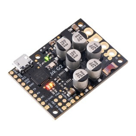
8. Pinout and components The pinout diagrams below identify the I/O and power pins on each Jrk G2 model. Basic pinout diagram of the Jrk G2 21v3 USB Motor Controller with Feedback. 8. Pinout and components Page 79 of 199... - Page 80 Jrk G2 Motor Controller User’s Guide © 2001–2019 Pololu Corporation Basic pinout diagram of the Jrk G2 18v19 USB Motor Controller with Feedback. 8. Pinout and components Page 80 of 199...
- Page 81 Jrk G2 Motor Controller User’s Guide © 2001–2019 Pololu Corporation Basic pinout diagram of the Jrk G2 24v13 USB Motor Controller with Feedback. 8. Pinout and components Page 81 of 199...
- Page 82 Jrk G2 Motor Controller User’s Guide © 2001–2019 Pololu Corporation Basic pinout diagram of the Jrk G2 18v27 USB Motor Controller with Feedback. 8. Pinout and components Page 82 of 199...
- Page 83 Jrk G2 Motor Controller User’s Guide © 2001–2019 Pololu Corporation Basic pinout diagram of the Jrk G2 24v21 USB Motor Controller with Feedback. The Jrk G2 can connect to a computer’s USB port via a USB A to Micro-B cable (not included).
- Page 84 Jrk G2 Motor Controller User’s Guide © 2001–2019 Pololu Corporation The RST pin can be driven low to reset the Jrk’s microcontroller, but this should generally not be necessary for typical applications. The line is pulled up to 5 V so it is safe to leave this pin unconnected.
- Page 85 POT−). The POT− pin is connected to GND through an on-board 220Ω resistor. Hardware design files These files provide further documentation of the hardware design of the Jrk G2 21v3 motor controller: • Dimension diagram (215k pdf) [https://www.pololu.com/file/0J1547/jrk-g2-21v3-dimensions.pdf]...
-
Page 86: Setting Reference
Jrk G2 Motor Controller User’s Guide © 2001–2019 Pololu Corporation 9. Setting reference The Jrk G2 holds all of its settings in its non-volatile EEPROM memory. These settings are normally set ahead of time over USB using the Jrk G2 Configuration Utility. You can also read and write settings... - Page 87 Jrk G2 Motor Controller User’s Guide © 2001–2019 Pololu Corporation this setting ahead of time over USB using Jrk G2 configuration software. List of settings • Input mode • Input error minimum • Input error maximum • Input minimum •...
- Page 88 Jrk G2 Motor Controller User’s Guide © 2001–2019 Pololu Corporation • Serial device number • Never sleep • Enable CRC • Enable 14-bit device number • Disable compact protocol • Proportional multiplier • Proportional exponent • Integral multiplier • Integral exponent •...
- Page 89 Jrk G2 Motor Controller User’s Guide © 2001–2019 Pololu Corporation • Brake duration forward • Brake duration reverse • Soft current limit forward • Soft current limit reverse • Soft current regulation level forward • Soft current regulation level reverse •...
- Page 90 Jrk G2 Motor Controller User’s Guide © 2001–2019 Pololu Corporation Input mode Offset 0x03 Type unsigned 8-bit • 0: Serial / I²C / USB • 1: Analog voltage Data • 2: RC Default Serial / I²C / USB Settings file input_mode •...
- Page 91 Jrk G2 Motor Controller User’s Guide © 2001–2019 Pololu Corporation Input error minimum Offset 0x04 Type unsigned 16-bit Default Range 0 to 4095 Settings file input_error_minimum Configuration utility Input tab, Scaling box, Input column, Error min Temporary override available If the raw input value is below this value, it causes an “Input disconnect” error. See Section 7.3.
- Page 92 Jrk G2 Motor Controller User’s Guide © 2001–2019 Pololu Corporation Input minimum Offset 0x08 Type unsigned 16-bit Default Range 0 to 4095 Settings file input_minimum Configuration utility Input tab, Scaling box, Input column, Minimum Temporary override available This is one of the input scaling parameters that determines how the Jrk calculates its target value from its raw input.
- Page 93 Jrk G2 Motor Controller User’s Guide © 2001–2019 Pololu Corporation Input neutral minimum Offset 0x0C Type unsigned 16-bit Default 2048 Range 0 to 4095 Settings file input_neutral_minimum Configuration utility Input tab, Scaling box, Input column, Neutral min Temporary override available This is one of the input scaling parameters that determines how the Jrk calculates its target value from its raw input.
- Page 94 Jrk G2 Motor Controller User’s Guide © 2001–2019 Pololu Corporation Target minimum Offset 0x10 Type unsigned 16-bit Default Range 0 to 4095 Settings file output_minimum Configuration utility Input tab, Scaling box, Target column, Minimum Temporary override available This is one of the input scaling parameters that determines how the Jrk calculates its target value from its raw input.
- Page 95 Jrk G2 Motor Controller User’s Guide © 2001–2019 Pololu Corporation Target maximum Offset 0x14 Type unsigned 16-bit Default 4095 Range 0 to 4095 Settings file output_maximum Configuration utility Input tab, Scaling box, Target column, Maximum Temporary override available This is one of the input scaling parameters that determines how the Jrk calculates its target value from its raw input.
- Page 96 Jrk G2 Motor Controller User’s Guide © 2001–2019 Pololu Corporation Input scaling degree Offset 0x16 Type unsigned 8-bit • 0: linear • 1: quadratic • 2: cubic Data • 3: quartic • 4: quintic Default JRK_SCALING_DEGREE_LINEAR Settings file input_scaling_degree •...
- Page 97 Jrk G2 Motor Controller User’s Guide © 2001–2019 Pololu Corporation Input detect disconnect Offset bit 1 of byte 0x02 Type boolean • 0: false Data • 1: true Default false Settings file input_detect_disconnect Settings file data true false Configuration utility...
- Page 98 Jrk G2 Motor Controller User’s Guide © 2001–2019 Pololu Corporation Feedback mode Offset 0x18 Type unsigned 8-bit • 0: None • 1: Analog voltage Data • 2: Frequency (speed control) Default None Settings file feedback_mode • none • analog Settings file data •...
- Page 99 Jrk G2 Motor Controller User’s Guide © 2001–2019 Pololu Corporation Feedback error minimum Offset 0x19 Type unsigned 16-bit Default Range 0 to 4095 Settings file feedback_error_minimum Configuration utility Feedback tab, Error min Temporary override available If the raw feedback value is below this value, it causes a “Feedback disconnect” error. See Section 7.4.
- Page 100 Jrk G2 Motor Controller User’s Guide © 2001–2019 Pololu Corporation Feedback minimum Offset 0x1D Type unsigned 16-bit Default Range 0 to 4095 Settings file feedback_minimum Configuration utility Feedback tab, Minimum Temporary override available This is one of the parameters of the feedback scaling feature. See Section 7.4.
- Page 101 Jrk G2 Motor Controller User’s Guide © 2001–2019 Pololu Corporation Invert feedback direction Offset bit 2 of byte 0x02 Type boolean • 0: false Data • 1: true Default false Settings file feedback_invert Settings file data true false Configuration utility...
- Page 102 Jrk G2 Motor Controller User’s Guide © 2001–2019 Pololu Corporation Feedback dead zone Offset 0x21 Type unsigned 8-bit Default Range 0 to 255 Settings file feedback_dead_zone Configuration utility PID tab, Feedback dead zone Temporary override available If PID feedback is enabled, the Jrk sets the duty cycle target to zero and resets the integral whenever the magnitude of the error is smaller than this setting.
- Page 103 Jrk G2 Motor Controller User’s Guide © 2001–2019 Pololu Corporation Feedback wraparound Offset bit 4 of byte 0x02 Type boolean • 0: false Data • 1: true Default false Settings file feedback_wraparound Settings file data true false Configuration utility Feedback tab, Wraparound Temporary override available This option, which is only available when the feedback mode is “Analog”, determines whether the PID...
- Page 104 Jrk G2 Motor Controller User’s Guide © 2001–2019 Pololu Corporation The serial mode determines how bytes are transferred between the Jrk’s UART (TX and RX pins), its two USB virtual serial ports (the command port and the TTL Port), and its serial command processor.
- Page 105 Configuration utility Input tab, Serial interface, Device number Temporary override available This is the serial device number used in the Pololu protocol on the Jrk’s serial interfaces, and the I²C device address used on the Jrk’s I²C interface. 9. Setting reference...
- Page 106 Jrk G2 Motor Controller User’s Guide © 2001–2019 Pololu Corporation By default, the Jrk only pays attention to the lower 7 bits of this setting, but if you enable 14-bit serial device numbers then it will use the lower 14 bits for the serial interface (but the I²C interface will still only use the lower 7 bits).
- Page 107 Input tab, Serial interface, Enable 14-bit device number Temporary override available If enabled, the Jrk’s Pololu protocol for serial commands will require a 14-bit device number to be sent with every command, instead of normal 7-bit device number. This option allows you to put more than 128 Jrk devices on one serial bus and control them individually.
- Page 108 Jrk G2 Motor Controller User’s Guide © 2001–2019 Pololu Corporation Disable compact protocol Offset bit 3 of byte 0x01 Type boolean • 0: false Data • 1: true Default false Settings file serial_disable_compact_protocol Settings file data true false Configuration utility...
- Page 109 Jrk G2 Motor Controller User’s Guide © 2001–2019 Pololu Corporation Proportional exponent Offset 0x53 Type unsigned 8-bit Default Range 0 to 18 Settings file proportional_exponent Configuration utility PID tab, Proportional coefficient, Lower left Temporary override available This is the exponent for the proportional coefficient used in the PID calculation. See Section 7.5.
- Page 110 Jrk G2 Motor Controller User’s Guide © 2001–2019 Pololu Corporation Integral exponent Offset 0x56 Type unsigned 8-bit Default Range 0 to 18 Settings file integral_exponent Configuration utility PID tab, Integral coefficient, Lower left Temporary override available This is the exponent for the integral coefficient used in the PID calculation. See Section 7.5.
- Page 111 Jrk G2 Motor Controller User’s Guide © 2001–2019 Pololu Corporation Derivative exponent Offset 0x59 Type unsigned 8-bit Default Range 0 to 18 Settings file derivative_exponent Configuration utility PID tab, Derivative coefficient, Lower left Temporary override available This is the exponent for the derivative coefficient used in the PID calculation. See Section 7.5.
- Page 112 Jrk G2 Motor Controller User’s Guide © 2001–2019 Pololu Corporation Integral divider exponent Offset 0x3F Type unsigned 8-bit Default Range 0 to 15 Settings file integral_divider_exponent Configuration utility PID tab, Integral divider Temporary override available This setting determines the “Integral divider” described in Section 7.5.
- Page 113 Jrk G2 Motor Controller User’s Guide © 2001–2019 Pololu Corporation Reset integral when proportional term exceeds max duty cycle Offset bit 0 of byte 0x50 Type boolean • 0: false Data • 1: true Default false Settings file reset_integral Settings file data...
- Page 114 Jrk G2 Motor Controller User’s Guide © 2001–2019 Pololu Corporation Current samples exponent Offset 0x33 Type unsigned 8-bit Default 7 (128 samples) Range 0 to 10 (1 sample to 1024 samples) Settings file current_samples_exponent Configuration utility Motor tab, Current samples Temporary override available This setting specifies how many analog samples of the Jrk’s internal current sense pin to take each...
- Page 115 Jrk G2 Motor Controller User’s Guide © 2001–2019 Pololu Corporation Current offset calibration Offset 0x35 Type signed 16-bit Default Range -800 to 800 Settings file current_offset_calibration Configuration utility Motor tab, Current offset calibration Temporary override available Section 7.6. Current scale calibration...
- Page 116 Jrk G2 Motor Controller User’s Guide © 2001–2019 Pololu Corporation Invert motor direction Offset bit 5 of byte 0x02 Type boolean • 0: false Data • 1: true Default false Settings file motor_invert Settings file data true false Configuration utility...
- Page 117 Jrk G2 Motor Controller User’s Guide © 2001–2019 Pololu Corporation Max. duty cycle reverse Offset 0x6A Type unsigned 16-bit Default Range 0 to 600 Settings file max_duty_cycle_reverse Configuration utility Motor tab, Max. duty cycle, Reverse column Temporary override available Section 7.6.
- Page 118 Jrk G2 Motor Controller User’s Guide © 2001–2019 Pololu Corporation Max. acceleration forward Offset 0x60 Type unsigned 16-bit Default Range 1 to 600 Settings file max_acceleration_forward Configuration utility Motor tab, Max. acceleration, Forward column Temporary override available Section 7.6. Max. acceleration reverse...
- Page 119 Jrk G2 Motor Controller User’s Guide © 2001–2019 Pololu Corporation Max. deceleration forward Offset 0x64 Type unsigned 16-bit Default Range 1 to 600 Settings file max_deceleration_forward Configuration utility Motor tab, Max. deceleration, Forward column Temporary override available Section 7.6. Max. deceleration reverse...
- Page 120 Jrk G2 Motor Controller User’s Guide © 2001–2019 Pololu Corporation Hard current limit forward Offset 0x6C Type unsigned 16-bit Data Encoded Default Depends on the product Settings file encoded_hard_current_limit_forward Configuration utility Motor tab, Hard current limit, Forward column Temporary override available This setting specifies the hardware current limit that the Jrk will use when driving in the forward direction.
- Page 121 Jrk G2 Motor Controller User’s Guide © 2001–2019 Pololu Corporation Hard current limit reverse Offset 0x6E Type unsigned 16-bit Data Encoded Default Depends on the product Settings file encoded_hard_current_limit_reverse Configuration utility Motor tab, Hard current limit, Reverse column Temporary override available...
- Page 122 Jrk G2 Motor Controller User’s Guide © 2001–2019 Pololu Corporation Brake duration reverse Offset 0x71 Type unsigned 8-bit Data Duration in units of 5 ms Default Range 0 to 1275 ms Settings file brake_duration_reverse Settings file data Duration in units of milliseconds...
- Page 123 Settings file data Current in units of milliamps Configuration utility Motor tab, Soft current regulation level, Forward column Temporary override available This setting is only available on the Jrk G2 21v3. See Section 7.6. 9. Setting reference Page 123 of 199...
- Page 124 Settings file data Current in units of milliamps Configuration utility Motor tab, Soft current regulation level, Reverse column Temporary override available This setting is only available on the Jrk G2 21v3. See Section 7.6. Coast when off Offset bit 1 of byte 0x50...
- Page 125 Jrk G2 Motor Controller User’s Guide © 2001–2019 Pololu Corporation Error enable Offset 0x2A Type unsigned 16-bit Default Settings file error_enable Configuration utility Errors tab Temporary override available This setting holds a bit for each error that the Jrk supports. The correspondence between bits and...
- Page 126 Jrk G2 Motor Controller User’s Guide © 2001–2019 Pololu Corporation Error hard stop Offset 0x2E Type unsigned 16-bit Default Settings file error_hard Configuration utility Errors tab Temporary override available This setting holds a bit for each error that the Jrk supports. The correspondence between bits and...
- Page 127 Jrk G2 Motor Controller User’s Guide © 2001–2019 Pololu Corporation Disable I²C pull-ups Offset bit 4 of byte 0x01 Type boolean • 0: false Data • 1: true Default false Settings file disable_i2c_pullups Settings file data true false Configuration utility Advanced tab, Disable I²C pull-ups...
- Page 128 Jrk G2 Motor Controller User’s Guide © 2001–2019 Pololu Corporation Always configure SDA/AN for analog input Offset bit 6 of byte 0x01 Type boolean • 0: false Data • 1: true Default false Settings file always_analog_sda Settings file data true...
- Page 129 Jrk G2 Motor Controller User’s Guide © 2001–2019 Pololu Corporation FBT method Offset 0x39 Type unsigned 8-bit • 0: Pulse counting Data • 1: Pulse timing Default Pulse counting Settings file fbt_method • counting Settings file data • timing Configuration utility...
- Page 130 Jrk G2 Motor Controller User’s Guide © 2001–2019 Pololu Corporation FBT timing clock Offset bits 4 through 6 of byte 0x3A Type unsigned 8-bit • 0: 12 MHz • 1: 6 MHz • 2: 3 MHz Data • 3: 1.5 MHz •...
- Page 131 Jrk G2 Motor Controller User’s Guide © 2001–2019 Pololu Corporation FBT timing polarity Offset bit 0 of byte 0x3A Type boolean • 0: Active high Data • 1: Active low Default Active high Settings file fbt_timing_polarity Settings file data (active high) or...
- Page 132 Jrk G2 Motor Controller User’s Guide © 2001–2019 Pololu Corporation FBT samples Offset 0x3D Type unsigned 8-bit Default Range 1 to 32 Settings file fbt_samples Configuration utility Feedback tab, Frequency feedback on FBT, Pulse samples Temporary override available The number of consecutive FBT measurements to average together in pulse timing mode or to add together in pulse counting mode.
- Page 133 Jrk G2 Motor Controller User’s Guide © 2001–2019 Pololu Corporation Not initialized Offset 0x00 Type unsigned 8-bit • 0: false Data • non-zero: true Default false This special setting keeps track of whether the rest of the settings have been initialized or not.
-
Page 134: Variable Reference
Jrk G2 Motor Controller User’s Guide © 2001–2019 Pololu Corporation 10. Variable reference The Jrk G2 maintains a set of variables in RAM that contain information about its inputs, outputs, and status. Many of these variables are displayed in real time in the “Status” tab of the Jrk G2 Configuration Utility. - Page 135 Jrk G2 Motor Controller User’s Guide © 2001–2019 Pololu Corporation • Force mode • VIN voltage • Current • Last reset • Up time • RC pulse width • FBT reading • Analog reading SDA/AN • Analog reading FBA •...
- Page 136 Jrk G2 Motor Controller User’s Guide © 2001–2019 Pololu Corporation Target Offset 0x02 Type unsigned 16-bit Range 0 to 4095 The target variable represents the speed or position that you are commanding the Jrk to maintain. In serial input mode, the target is set directly with serial, USB, or I²C commands.
- Page 137 Jrk G2 Motor Controller User’s Guide © 2001–2019 Pololu Corporation Scaled feedback Offset 0x06 Type unsigned 16-bit Range 0 to 4095 If feedback is enabled, the scaled feedback is calculated from the Feedback using the Jrk’s configurable feedback scaling settings (see Section 7.4).
- Page 138 Jrk G2 Motor Controller User’s Guide © 2001–2019 Pololu Corporation cycle variable will change/decelerate to zero. Duty cycle Offset 0x0C Type signed 16-bit Range −600 to 600 Units −600 is full speed reverse, 600 is full speed forward The duty cycle variable indicates the voltage that the Jrk is currently applying to the motor. A value of −600 means full speed reverse, while a value of 600 means full speed forward.
- Page 139 Jrk G2 Motor Controller User’s Guide © 2001–2019 Pololu Corporation PID period count Offset 0x10 Type unsigned 16-bit This is the number of PID periods that have elapsed. It resets to 0 after reaching 65535. Error flags halting Offset 0x12...
- Page 140 Jrk G2 Motor Controller User’s Guide © 2001–2019 Pololu Corporation VIN voltage Offset 0x17 Type unsigned 16-bit Units This is the measurement of the voltage supplied to the Jrk’s VIN pin, in millivolts. Current Offset 0x19 Type unsigned 16-bit Units This is the Jrk’s measurement of the current running through the motor, in milliamps.
- Page 141 Jrk G2 Motor Controller User’s Guide © 2001–2019 Pololu Corporation Up time Offset 0x20 Type unsigned 32-bit Range 0 to 4,294,967,295 Units This is the time since the last full reset of the Jrk’s microcontroller, in milliseconds. It resets to 0 after reaching 4,294,967,295.
- Page 142 Jrk G2 Motor Controller User’s Guide © 2001–2019 Pololu Corporation Analog reading SDA/AN Offset 0x28 Type unsigned 16-bit Range 0 to 65,472 or 65,535 Units 0 means 0 V, 65,472 means roughly the voltage on the Jrk’s 5V pin This is the analog reading on the SDA/AN pin. The Jrk updates this reading once per PID period if the “Input mode”...
- Page 143 Jrk G2 Motor Controller User’s Guide © 2001–2019 Pololu Corporation Digital readings Offset 0x2C Type unsigned 8-bit • Bit 0: Digital reading for SCL • Bit 1: Digital reading for SDA/AN • Bit 2: Digital reading for TX • Bit 3: Digital reading for RX Data •...
- Page 144 Jrk G2 Motor Controller User’s Guide © 2001–2019 Pololu Corporation Last duty cycle Offset 0x31 Type signed 16-bit Range −600 to 600 Units −600 is full speed reverse, 600 is full speed forward This is the duty cycle from the previous PID period. The Jrk reports this variable because it is used in the calculation of the measured current, and you might want to reproduce that calculation yourself instead of relying on the Jrk’s...
-
Page 145: Command Reference
Jrk G2 Motor Controller User’s Guide © 2001–2019 Pololu Corporation 11. Command reference The Jrk G2 supports several different commands on its serial, I²C, and USB interfaces. This section describes the details of what each command does. The encoding of the commands for the different... - Page 146 Jrk G2 Motor Controller User’s Guide © 2001–2019 Pololu Corporation Set target Interfaces Serial, I²C, USB Arguments Target: a number between 0 and 4095 Response None jrk2cmd --target NUM jrk2cmd jrk2cmd --run Arduino library jrk.setTarget(uint16_t target) The “Set target” command is the most important command for controlling the Jrk, and in many applications it is the only command needed.
- Page 147 Jrk G2 Motor Controller User’s Guide © 2001–2019 Pololu Corporation Stop motor Interfaces Serial, I²C, USB Arguments None Response None jrk2cmd jrk2cmd --stop NUM Arduino library jrk.stopMotor() The “Stop motor” command, also known as “Motor off”, sets the “Awaiting command” error flag and clears the serial timeout timer.
- Page 148 Jrk G2 Motor Controller User’s Guide © 2001–2019 Pololu Corporation Force duty cycle Interfaces Serial, I²C, USB Arguments Duty cycle: a number between −600 and 600 Response None jrk2cmd jrk2cmd --force-duty-cycle NUM Arduino library jrk.forceDutyCycle() When the Jrk receives this command, it will start ignoring the results of the usual algorithm for choosing the duty cycle, and instead set it to be equal to the value specified by this command, ignoring all motor limits except the maximum duty cycle parameters, and ignoring the “Input invalid”,...
- Page 149 Jrk G2 Motor Controller User’s Guide © 2001–2019 Pololu Corporation This command fetches a range of bytes from the Jrk’s variables, which are stored in the Jrk’s RAM and represent the current state of the Jrk. The offset argument specifies the location of the first byte you want to fetch: an offset of zero indicates the first variable (the “Input”...
- Page 150 Jrk G2 Motor Controller User’s Guide © 2001–2019 Pololu Corporation running. The “Clear errors” button in the “Errors” tab of the Jrk G2 Configuration Utility sends this command with the “Clear error flags halting” parameter set to true. The Jrk’s USB interface provides a flexible version of the “Get variables” command that lets you specify an offset, length, and any combination of side effects.
- Page 151 Jrk G2 Motor Controller User’s Guide © 2001–2019 Pololu Corporation zero when you try to read from unimplemented areas of the settings space with the Get RAM settings command. The effect of this command is temporary. The Jrk reloads all of its settings from EEPROM whenever...
- Page 152 Jrk G2 Motor Controller User’s Guide © 2001–2019 Pololu Corporation Get EEPROM settings Interfaces Serial, I²C, USB Offset: The address of the first setting to read. Arguments Length: The number of bytes to read. Response The requested bytes. jrk2cmd jrk2cmd --get-settings FILE Arduino library jrk.getEEPROMSettings(uint8_t offset, uint8_t length, uint8_t * buffer)
- Page 153 Jrk G2 Motor Controller User’s Guide © 2001–2019 Pololu Corporation Reinitialize (USB only) Interfaces USB only Arguments Preserve errors: true or false Response None jrk2cmd jrk2cmd --reinitialize This command tells the Jrk to reload all of its settings from non-volatile memory (discarding changes...
-
Page 154: Serial Command Encoding
Jrk. The Pololu protocol includes a device number, allowing you to control multiple devices from a single serial line. This section starts by documenting the compact protocol version of each command. - Page 155 Jrk G2 Motor Controller User’s Guide © 2001–2019 Pololu Corporation in binary: 0b11011101 0b01100100 in hex: 0xDD 0x64 in decimal: 221 Here is some example C code that will generate the correct serial bytes, given an integer that target holds the desired target (0–4095) and an array called serialBytes serialBytes[0] = 0xC0 + (target &...
- Page 156 Jrk G2 Motor Controller User’s Guide © 2001–2019 Pololu Corporation Set target (low resolution reverse) 0xE0 magnitude This is an alternative way to encode the “Set Target” command that provides less resolution and only works for target values of 2048 or less. It generally behaves the same as the “Set target (low resolution forward)”...
- Page 157 Jrk G2 Motor Controller User’s Guide © 2001–2019 Pololu Corporation uint16_t d = duty_cycle; // convert to unsigned serialBytes[0] = 0xF2; // Force duty cycle target serialBytes[1] = d & 0x7F; serialBytes[2] = d >> 7 & 0x7F; Force duty cycle 0xF4 duty cycle low 7 bits duty cycle high 7 bits This command is encoded in the same way as the “Force duty cycle target”...
- Page 158 Jrk G2 Motor Controller User’s Guide © 2001–2019 Pololu Corporation Command Response (and effect) byte 0xA1 Both bytes of the “Input” variable. 0x81 The low byte (least-significant byte) of the “Input” variable. 0x82 The high byte (most-significant byte) of the "Input variable.
- Page 159 Jrk G2 Motor Controller User’s Guide © 2001–2019 Pololu Corporation 0x91 The low byte of “PID period count”. 0x92 The high byte of “PID period count”. 0xB3 Both bytes of “Error flags halting”. Clears the variable as a side effect.
- Page 160 Jrk G2 Motor Controller User’s Guide © 2001–2019 Pololu Corporation most-significant bits for each data byte are sent in a separate byte at the end of the command (even if they are all zero). The length byte must be between 1 and 7, which means that only one byte is needed to hold the most-significant bits for all of the data.
- Page 161 “Input” tab. When that setting is enabled, you can set the device number to any number between 0 and 16384. The Jrk will then expect two bytes for the device number in the Pololu Protocol instead of one. The first device number byte contains the low 7 bits of the device number while the second device number byte holds the high 7 bits of the device number.
- Page 162 Jrk G2 Motor Controller User’s Guide © 2001–2019 Pololu Corporation Pololu protocol with 14-bit device number: 0xAA 0x2C 0x02 0x5D 0x64 The “Enable 14-bit device number” setting is just for the serial interface and does not affect the I²C interface; it will still only use the seven least-significant bits of the device number as its address.
- Page 163 Jrk G2 Motor Controller User’s Guide © 2001–2019 Pololu Corporation #include <stdint.h> uint8_t getCRC(uint8_t * message, uint8_t length) uint8_t crc = 0; (uint8_t i = 0; i < length; i++) crc ^= message[i]; (uint8_t j = 0; j < 8; j++) (crc &...
-
Page 164: I²C Command Encoding
Jrk G2 Motor Controller User’s Guide © 2001–2019 Pololu Corporation 13. I²C command encoding This section documents how the Jrk G2’s commands are encoded as a I²C transactions. Number prefixed with “0x” are written in hexadecimal notation (base 16) and numbers prefixed with “0b”... - Page 165 Jrk G2 Motor Controller User’s Guide © 2001–2019 Pololu Corporation is calculated by adding 0xC0 to the least-significant 5 bits of the target value. The Jrk acknowledges this byte too. Then, the master sends a byte containing the lower 7 bits of the target value (the most- significant bit of this byte is clear).
- Page 166 Jrk G2 Motor Controller User’s Guide © 2001–2019 Pololu Corporation This means that a magnitude of 127 corresponds to full-speed forward, while a magnitude of 0 will make the motor stop. Set target (low resolution reverse) master: S addr + Wr...
- Page 167 Jrk G2 Motor Controller User’s Guide © 2001–2019 Pololu Corporation that holds the desired duty cycle (−600 to 600) and an array called i2cBytes i2cBytes[0] = 0xF2; // Force duty cycle target i2cBytes[1] = duty_cycle & 0xFF; i2cBytes[2] = duty_cycle >> 8 & 0xFF;...
- Page 168 Jrk G2 Motor Controller User’s Guide © 2001–2019 Pololu Corporation If you are using a clock speed faster than the standard 100 kHz, you should ensure that no activity happens on the bus for 100 µs after the end of a command like this one that reads data from the Jrk.
- Page 169 Jrk G2 Motor Controller User’s Guide © 2001–2019 Pololu Corporation Command Response (and effect) byte 0xA1 Both bytes of the “Input” variable. 0x81 The low byte (least-significant byte) of the “Input” variable. 0x82 The high byte (most-significant byte) of the "Input variable.
- Page 170 Jrk G2 Motor Controller User’s Guide © 2001–2019 Pololu Corporation 0x91 The low byte of “PID period count”. 0x92 The high byte of “PID period count”. 0xB3 Both bytes of “Error flags halting”. Clears the variable as a side effect.
- Page 171 Jrk G2 Motor Controller User’s Guide © 2001–2019 Pololu Corporation The offset byte specifies the offset into the settings data in bytes, while the length byte specifies how many bytes of data to write. The length byte must be between 1 and 13.
-
Page 172: Usb Command Encoding
For a reference implementation of the Jrk G2 native USB protocol, see the Jrk G2 software source code [https://github.com/pololu/pololu-jrk-g2-software] The Jrk G2 uses the USB vendor ID of Pololu Corporation, which is 0x1FFB. Each variant has a different USB product ID: Name USB product ID... - Page 173 Jrk G2 Motor Controller User’s Guide © 2001–2019 Pololu Corporation Set target bmRequestType bRequest wValue wIndex wLength 0x40 0x84 target The bRequest field holds the target value, which should be between 0 and 4095. Stop motor bmRequestType bRequest wValue wIndex wLength...
- Page 174 Jrk G2 Motor Controller User’s Guide © 2001–2019 Pololu Corporation • Bit 1: Clear error flags occurred • Bit 2: Clear current chopping occurrence count For example, to clear “Error flags occurred” and “Current chopping count”, you would set bit 1 and bit 2, so bRequest would have a value of 6.
- Page 175 Jrk G2 Motor Controller User’s Guide © 2001–2019 Pololu Corporation between 0 and 255; this value will be written to the EEPROM byte at the specified offset. Reinitialize bmRequestType bRequest wValue wIndex wLength 0x40 0x10 flags When bit 0 of bRequest is 1, errors are preserved as described in...
-
Page 176: Writing Pc Software To Control The Jrk
Jrk G2 Motor Controller User’s Guide © 2001–2019 Pololu Corporation 15. Writing PC software to control the Jrk This section is about writing computer software to control the Jrk G2. Picking an interface You should decide which interface of the Jrk your software will talk to: serial, I²C, or USB. The Jrk’s USB interface has three main components: a native USB interface, a virtual USB serial port called the Command Port, and another virtual USB serial port called the TTL Port. - Page 177 Jrk G2 Motor Controller User’s Guide © 2001–2019 Pololu Corporation you will need in your application. Many applications just need the “Set target” command: in that case, it should be relatively easy to use any of the Jrk’s interfaces, and you could consider writing your own code to send that one command instead of relying on our code or third-party code.
-
Page 178: Example Code To Run Jrk2Cmd In C
Jrk G2 Motor Controller User’s Guide © 2001–2019 Pololu Corporation properly for the Jrk’s USB interface, sending the command, and cleaning up after itself. If an error happens, jrk2cmd will print an error message to its standard error pipe and return a non-zero exit code. -
Page 179: Example Code To Run Jrk2Cmd In Ruby
Jrk G2 Motor Controller User’s Guide © 2001–2019 Pololu Corporation // Uses jrk2cmd to set the target of the Jrk G2 over USB. // NOTE: The Jrk's input mode must be "Serial / I2C / USB". #include <stdint.h> #include <stdio.h>... -
Page 180: Example Code To Run Jrk2Cmd In Python
Jrk G2 Motor Controller User’s Guide © 2001–2019 Pololu Corporation can change the code to use Ruby’s method [http://ruby-doc.org/stdlib/libdoc/open3/rdoc/ Open3.capture3 Open3.html#method-c-capture3] # Uses jrk2cmd to send and receive data from the Jrk G2 over USB. # NOTE: The Jrk's input mode must be "Serial / I2C / USB". - Page 181 Jrk G2 Motor Controller User’s Guide © 2001–2019 Pololu Corporation # Uses jrk2cmd to send and receive data from the Jrk G2 over USB. # Works with either Python 2 or Python 3. # NOTE: The Jrk's input mode must be "Serial / I2C / USB".
-
Page 182: Running Jrk2Cmd With Windows Shortcuts
Jrk G2 Motor Controller User’s Guide © 2001–2019 Pololu Corporation 15.4. Running jrk2cmd with Windows shortcuts This section explains how to control the Jrk G2 with Windows shortcuts. A folder of shortcuts can serve as a simple GUI for controlling the Jrk and requires no programming experience to make. This section focuses on shortcuts in Windows, but you should be able to do something similar in Linux or macOS. - Page 183 Jrk G2 Motor Controller User’s Guide © 2001–2019 Pololu Corporation 4. Type an appropriate name for your shortcut and click “Finish”. Now you should be able to double-click on your shortcut to run the command you entered. You will probably see a black window briefly flash on the screen run the command runs.
-
Page 184: Example Serial Code For Linux And Macos In C
Jrk G2 Motor Controller User’s Guide © 2001–2019 Pololu Corporation Multiple Jrk G2 devices If you have multiple Jrk G2 devices connected to the computer via USB, you will need to add the option to each shortcut in order to specify the serial number of the device you want to use. For... - Page 185 Jrk G2 Motor Controller User’s Guide © 2001–2019 Pololu Corporation rates that are close enough to work. 15. Writing PC software to control the Jrk Page 185 of 199...
- Page 186 Jrk G2 Motor Controller User’s Guide © 2001–2019 Pololu Corporation // Uses POSIX serial port functions to send and receive data from a Jrk G2. // NOTE: The Jrk's input mode must be "Serial / I2C / USB". // NOTE: The Jrk's serial mode must be set to "USB dual port" if you are connecting to it directly via USB.
- Page 187 Jrk G2 Motor Controller User’s Guide © 2001–2019 Pololu Corporation case 38400: cfsetospeed(&options, B38400); break; case 115200: cfsetospeed(&options, B115200); break; default: fprintf(stderr, "warning: baud rate %u is not supported, using 9600.\n", baud_rate); cfsetospeed(&options, B9600); break; cfsetispeed(&options, cfgetospeed(&options)); result = tcsetattr(fd, TCSANOW, &options);...
- Page 188 Jrk G2 Motor Controller User’s Guide © 2001–2019 Pololu Corporation // command in the "Command reference" section of the Jrk G2 user's guide. int jrk_set_target(int fd, uint16_t target) (target > 4095) { target = 4095; } uint8_t command[2]; command[0] = 0xC0 + (target & 0x1F);...
-
Page 189: Example Serial Code For Windows In C
Jrk G2 Motor Controller User’s Guide © 2001–2019 Pololu Corporation fd = open_serial_port(device, baud_rate); (fd < 0) { return 1; } feedback = jrk_get_feedback(fd); (feedback < 0) { return 1; } printf("Feedback is %d.\n", feedback); target = jrk_get_target(fd); (target < 0) { return 1;... - Page 190 Jrk G2 Motor Controller User’s Guide © 2001–2019 Pololu Corporation // Uses Windows API serial port functions to send and receive data from a // Jrk G2. // NOTE: The Jrk's input mode must be "Serial / I2C / USB".
- Page 191 Jrk G2 Motor Controller User’s Guide © 2001–2019 Pololu Corporation DCB state; state.DCBlength = sizeof(DCB); success = GetCommState(port, &state); (!success) print_error("Failed to get serial settings"); CloseHandle(port); return INVALID_HANDLE_VALUE; state.BaudRate = baud_rate; success = SetCommState(port, &state); (!success) print_error("Failed to set serial settings");...
- Page 192 Jrk G2 Motor Controller User’s Guide © 2001–2019 Pololu Corporation // command in the "Command reference" section of the Jrk G2 user's guide. int jrk_set_target(HANDLE port, uint16_t target) (target > 4095) { target = 4095; } uint8_t command[2]; command[0] = 0xC0 + (target & 0x1F);...
-
Page 193: Example Serial Code In Python
Jrk G2 Motor Controller User’s Guide © 2001–2019 Pololu Corporation HANDLE port = open_serial_port(device, baud_rate); (port == INVALID_HANDLE_VALUE) { return 1; } feedback = jrk_get_feedback(port); (feedback < 0) { return 1; } printf("Feedback is %d.\n", feedback); target = jrk_get_target(port); (target < 0) { return 1;... - Page 194 9600 # Change this to a number between 0 and 127 that matches the device number of # your Jrk if there are multiple serial devices on the line and you want to # use the Pololu Protocol. device_number None 15.
-
Page 195: Example I²C Code For Linux In C
Jrk G2 Motor Controller User’s Guide © 2001–2019 Pololu Corporation port serial.Serial(port_name, baud_rate, timeout=0.1, write_timeout=0.1) JrkG2Serial(port, device_number) feedback jrk.get_feedback() print("Feedback is {}.".format(feedback)) target jrk.get_target() print("Target is {}.".format(target)) new_target 2248 target < 2048 else 1848 print("Setting target to {}.".format(new_target)) jrk.set_target(new_target) 15.8. Example I²C code for Linux in C The example C code below uses the I²C API provided by the Linux kernel to send and receive data... - Page 196 Jrk G2 Motor Controller User’s Guide © 2001–2019 Pololu Corporation // Uses the Linux I2C API to send and receive data from a Jrk G2. // NOTE: The Jrk's input mode must be "Serial / I2C / USB". // NOTE: For reliable operation on a Raspberry Pi, enable the i2c-gpio overlay and use the I2C device it provides (usually /dev/i2c-3).
-
Page 197: Example I²C Code For Linux In Python
Jrk G2 Motor Controller User’s Guide © 2001–2019 Pololu Corporation result = ioctl(fd, I2C_RDWR, &ioctl_data); (result != 2) perror("failed to get variables"); return return // Gets the Target variable from the jrk or returns -1 on failure. int jrk_get_target(int fd, uint8_t address) uint8_t buffer[2];... - Page 198 Jrk G2 Motor Controller User’s Guide © 2001–2019 Pololu Corporation via I²C. It demonstrates how to set the target of the Jrk by sending a “Set target” command and how to read variables using a “Get variables” command. This example works on Linux with either Python 2 or Python 3.
- Page 199 Jrk G2 Motor Controller User’s Guide © 2001–2019 Pololu Corporation # Uses the smbus2 library to send and receive data from a Jrk G2. # Works on Linux with either Python 2 or Python 3. # NOTE: The Jrk's input mode must be "Serial / I2C / USB".
Need help?
Do you have a question about the Jrk G2 21v3 and is the answer not in the manual?
Questions and answers