Advertisement
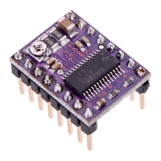
POLOLU DRV8825 STEPPER MOTOR DRIVER
CARRIER, HIGH CURRENT
USER'S GUIDE
USING THE DRIVER
Minimal wiring diagram for connecting a microcontroller to a
DRV8824/DRV8825 stepper motor driver carrier (full-step mode).
POWER CONNECTIONS
The driver requires a motor supply voltage of 8.2 – 45 V to be connected across
VMOT and GND. This supply should have appropriate decoupling capacitors close to
the board, and it should be capable of delivering the expected stepper motor current.
Warning: This carrier board uses low-ESR ceramic capacitors, which makes it
susceptible to destructive LC voltage spikes, especially when using power leads longer
than a few inches. Under the right conditions, these spikes can exceed the 45 V
1
https://eckstein-shop.de/
Advertisement
Table of Contents

Subscribe to Our Youtube Channel
Related Manuals for Pololu DRV8825


Summary of Contents for Pololu DRV8825
- Page 1 USER’S GUIDE USING THE DRIVER Minimal wiring diagram for connecting a microcontroller to a DRV8824/DRV8825 stepper motor driver carrier (full-step mode). POWER CONNECTIONS The driver requires a motor supply voltage of 8.2 – 45 V to be connected across VMOT and GND. This supply should have appropriate decoupling capacitors close to the board, and it should be capable of delivering the expected stepper motor current.
-
Page 2: Motor Connections
(VMOT) and ground somewhere close to the board. MOTOR CONNECTIONS Four, six, and eight-wire stepper motors can be driven by the DRV8825 if they are properly connected; a FAQ answer explains the proper wirings in detail. Warning: Connecting or disconnecting a stepper motor while the driver is powered can destroy the driver. -
Page 3: Control Inputs
MODE0 MODE1 MODE2 Microstep Resolution Full step High Half step High 1/4 step High High 1/8 step High 1/16 step High High 1/32 step High High 1/32 step High High High 1/32 step CONTROL INPUTS Each pulse to the STEP input corresponds to one microstep of the stepper motor in the direction selected by the DIR pin. -
Page 4: Current Limiting
SLEEP and FAULT would then act as a pull-up for SLEEP, making the DRV8825 carrier more of a direct replacement for the A4988 in such systems (the A4988 has an internal pull-up on its SLEEP pin). To keep faults from pulling down the SLEEP pin, any external pull-up resistor you add to the SLEEP pin input should not exceed 4.7k. - Page 5 POWER DISSIPATION CONSIDERATIONS The DRV8825 driver IC has a maximum current rating of 2.5 A per coil, but the current sense resistors further limit the maximum current to 2.2 A, and the actual current you can deliver depends on how well you can keep the IC cool. The carrier’s printed circuit board is designed to draw heat out of the IC, but to supply more than approximately 1.5 A per coil, a heat sink or other cooling method is required.
-
Page 6: Schematic Diagram
Additionally, please note that the coil current is a function of the set current limit, but it does not necessarily equal the current limit setting. The actual current through each coil changes with each microstep. See the DRV8825 datasheet for more information. SCHEMATIC DIAGRAM... - Page 7 The SLEEP pin on the DRV8825 is not pulled up by default like it is on the A4988, but the carrier board does connect it to the FAULT pin through a 10k resistor. Therefore,...
- Page 8 The DRV8825 can deliver more current than the A4988 without any additional cooling (based on our full-step tests: 1.5 A per coil for the DRV8825 vs 1.2 A per coil for A4988 Black Edition and 1 A per coil for the original A4988 carrier).
- Page 9 Alternative minimal wiring diagram for connecting a microcontroller to a DRV8824/DRV8825 stepper motor driver carrier (full-step mode). https://eckstein-shop.de/...
Need help?
Do you have a question about the DRV8825 and is the answer not in the manual?
Questions and answers