
Subscribe to Our Youtube Channel
Related Manuals for Pololu G2


Summary of Contents for Pololu G2
- Page 1 Pololu Simple Motor Controller G2 User’s Guide © 2001–2019 Pololu Corporation Pololu Simple Motor Controller G2 User’s Guide https://www.pololu.com/docs/0J77/all Page 1 of 143...
-
Page 2: Table Of Contents
2. Contacting Pololu ........ - Page 3 Pololu Simple Motor Controller G2 User’s Guide © 2001–2019 Pololu Corporation 8.1. Example code to run smcg2cmd in C ......
-
Page 4: Overview
A free configuration utility for Windows simplifies initial setup of the device and allows for in-system testing and monitoring of the controller via USB. The table below lists the members of the Simple Motor Controller G2 family and shows the key differences among them:... - Page 5 Pololu Simple Motor Controller G2 User’s Guide © 2001–2019 Pololu Corporation Key features High-Power Simple Motor Controller G2 18v25 or 24v19 simplified connection diagram. • Simple bidirectional control of one DC brush motor. • Five communication or control options: 1. USB interface for direct connection to a PC.
- Page 6 Pololu Simple Motor Controller G2 User’s Guide © 2001–2019 Pololu Corporation on the system. • Adjustable starting speed and maximum speed. • Option to brake or coast when speed is zero. • Optional safety controls to avoid unexpectedly powering the motor.
- Page 7 ◦ Optional serial response delay for communicating with half-duplex controllers such as the Basic Stamp. ◦ Controllers can be easily chained together and to other Pololu serial motor and servo controllers to control hundreds of motors using a single serial line.
-
Page 8: 18V15 And 24V12 Included Hardware
Pololu Simple Motor Controller G2 User’s Guide © 2001–2019 Pololu Corporation Note: This guide only applies to the G2 Simple Motor Controllers, which have blue circuit boards. If you have one of the first-generation Simple Motor Controllers, which have green circuit boards, you can find their user’s guide here [https://www.pololu.com/docs/0J44]... - Page 9 The terminal blocks are only rated for 16 A, so for higher-power applications, we recommend soldering thick wires directly to the board. These files provide further documentation of the hardware design of the Simple Motor Controller G2 18v15 and 24v12: •...
-
Page 10: 18V25 And 24V19 Included Hardware
Pololu Simple Motor Controller G2 User’s Guide © 2001–2019 Pololu Corporation • Drill guide (100k dxf) [https://www.pololu.com/file/0J1601/umc08a-drill.dxf] 1.2. 18v25 and 24v19 included hardware High-Power Simple Motor Controller G2 High-Power Simple Motor Controller G2 18v25 with included hardware. 24v19 with included hardware. - Page 11 Pololu Simple Motor Controller G2 User’s Guide © 2001–2019 Pololu Corporation Pinout diagram of the High-Power Simple Motor Controller G2 18v25 or 24v19. The 18v25 and 24v19 versions come with connectors included but not soldered. The terminal blocks are only rated for 16 A, so for higher-power applications, we recommend soldering thick wires directly to the board.
-
Page 12: Supported Operating Systems
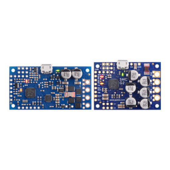
Mini-B). • The through-hole capacitors have been replaced with SMT capacitors. • The SMC G2 18v15 and 24v12 boards have the same size and nearly the same layout as the original SMC 18v15 and 24v12. An SCL pin was added. - Page 13 Pololu Simple Motor Controller G2 User’s Guide © 2001–2019 Pololu Corporation • The SMC G2 18v25 and 24v19 are significantly smaller than the original SMC 18v25 and 24v23, and the motor/power connections are different. Two SCL pins were added, but otherwise the control I/O pins are the same.
-
Page 14: Contacting Pololu
Pololu Simple Motor Controller G2 User’s Guide © 2001–2019 Pololu Corporation 2. Contacting Pololu We would be delighted to hear from you about any of your projects and about your experience with the G2 Simple Motor Controllers. You can contact us directly or post on [https://www.pololu.com/contact]... -
Page 15: Getting Started
© 2001–2019 Pololu Corporation 3. Getting started 3.1. Installing Windows drivers and software To install the drivers for the Simple Motor Controller G2 on a computer running Microsoft Windows, follow these steps: 1. Download the Simple Motor Controller G2 Software and Drivers for Windows (550k zip) [https://www.pololu.com/file/0J1599/smc-g2-1.0.0-windows.zip]... - Page 16 © 2001–2019 Pololu Corporation USB troubleshooting for Windows If the Simple Motor Controller G2 software cannot connect to your controller after you plug it into the computer via USB, the tips here can help you troubleshoot the SMC’s USB connection.
- Page 17 Pololu Simple Motor Controller G2 User’s Guide © 2001–2019 Pololu Corporation G2 18v15 Command Port”. The serial port might be named “USB Serial Device” instead if you are using Windows 10 or later and you plugged the controller into your computer before installing our drivers for it.
-
Page 18: Understanding The Control Center Status Tab
3.2. Understanding the control center Status tab After installing the software for the Simple Motor Controller G2, it is a good idea to run the Simple Motor Control Center G2 software and look at the Status tab. The Status tab lets you monitor the status of your motor controller in real time and control the speed of the motor. - Page 19 Pololu Simple Motor Controller G2 User’s Guide © 2001–2019 Pololu Corporation The Status tab in the Simple Motor Control Center G2 should look like this when you first connect the controller to the PC. Target speed and current speed The Target speed is the speed that the motor controller is trying to achieve. The target speed source is determined by the settings in the “Input settings”...
- Page 20 Pololu Simple Motor Controller G2 User’s Guide © 2001–2019 Pololu Corporation The Simple Motor Controller represents speeds internally as a number from -3200 (full reverse) to 3200 (full forward). However, by default the speeds in the Status Tab are displayed as percentages so -3200 (full reverse) is shown as -100.00% and 3200 (full forward) is shown as 100.00%.
- Page 21 Pololu Simple Motor Controller G2 User’s Guide © 2001–2019 Pololu Corporation detects that they are disconnected. If you do not intend to use this channel, you do not need to worry about this message. Otherwise, to correct this situation, make sure that all three pins...
-
Page 22: Errors
Pololu Simple Motor Controller G2 User’s Guide © 2001–2019 Pololu Corporation the board. • Up time: This is the total amount of time that the controller has been running since its last reset or power-up. The up time reading can be used to help identify if the controller has reset unexpectedly. - Page 23 You can get information about the errors The Errors box in the Status tab of the Simple Motor Control Center G2 shows problems that are stopping your motor. • Checking the Errors box in the Status tab of the Simple Motor Control Center. This is recommended because it gives you the most information, including a running count of how many times the error has been reported.
- Page 24 Pololu Simple Motor Controller G2 User’s Guide © 2001–2019 Pololu Corporation stopping the motor. After all the other errors have been fixed, you can clear the safe start violation error by pressing the Resume button (which issues a native USB command) or using a serial command.
- Page 25 If you get this error, check your algorithm for calculating CRCs and check the quality of your serial signal at the RX pin. The count that is displayed next to each error in the Simple Motor Control Center G2 indicates how 3. Getting started...
-
Page 26: Led Feedback
“Device” menu and selecting “Clear counts”. 3.5. LED feedback The Simple Motor Controller G2 has three indicator LEDs that provide feedback about the current state of the controller. The LEDs can tell you whether an error is occurring, whether the USB connection is active, what direction the motor is driving, and much more. - Page 27 USB activity. The Simple Motor Control Center G2 software constantly streams data from the controller, so when the control center is running and connected to the Simple Motor Controller, the green LED will flicker constantly.
- Page 28 Pololu Simple Motor Controller G2 User’s Guide © 2001–2019 Pololu Corporation • A repeating, gradual increase in brightness every second indicates that the controller is driving the motor forward. • A repeating, gradual decrease in brightness every second indicates that the controller is driving the motor in reverse.
-
Page 29: Connecting Your Motor Controller
The diagrams below label the key components and pins on the Simple Motor Controllers. Most of these pins are also labeled on the bottom side of the board. High-Power Simple Motor Controller G2 18v15 and 24v12 pinout High-Power Simple Motor Controller G2 18v25 and 24v19 pinout 4. -
Page 30: Connecting Power And A Motor
The first step in using your Simple Motor Controller is connecting power and a motor. With those connections in place, you can immediately start testing with the Simple Motor Control Center G2 software. The following section explains the power system in detail. - Page 31 USB is connected. It is OK to have both USB and VIN power simultaneously connected. All Simple Motor Controller G2 versions can operate from VIN supplies as low as 6.5 V. The maximum power ratings for the G2 Simple Motor Controllers are shown below: 4.
- Page 32 Finally, make sure you select a power source that is capable of delivering the current your motor will require (e.g. alkaline cells are typically poor choices for high-current applications). The Simple Motor Controller G2 features a configurable low-voltage shutoff that can help you avoid damaging batteries that are sensitive to over-discharging, such as Li-Po packs.
- Page 33 Pololu Simple Motor Controller G2 User’s Guide © 2001–2019 Pololu Corporation The two terminals of your brushed, DC motor connect to the OUTA and OUTB pins (which are just labeled “A” and “B” on some boards). When selecting a motor for your controller (or a controller version for your motor), it is important to consider how the motor will be used in your system.
- Page 34 Pololu Simple Motor Controller G2 User’s Guide © 2001–2019 Pololu Corporation noise suppression, you can use three capacitors (one across the terminals and one from each terminal to the case). 2. Make your motor leads as thick and as short as possible, and twist them around each other.
- Page 35 Pololu Simple Motor Controller G2 User’s Guide © 2001–2019 Pololu Corporation High-Power Simple Motor Controller G2 High-Power Simple Motor Controller G2 18v15 with included hardware. 24v12 with included hardware. High-Power Simple Motor Controller G2 High-Power Simple Motor Controller G2 18v25 with included hardware.
-
Page 36: Serial/I²C Interface Pins
Trying out the controller with USB Once you have a connected a power supply and a motor, you can use the Simple Motor Control Center G2 to make the motor move and test how various settings affect the behavior of the motor (see Section 5 for more information on configuring the Simple Motor Controller G2). - Page 37 RC section. Your serial or I²C device must share a common ground with the Simple Motor Controller G2. The VM pin provides access to the board’s reverse-protected motor power. The voltage on this pin is not regulated;...
- Page 38 The TX pin is protected by a 220Ω series resistor. The SCL pin acts as the I²C clock signal. The Simple Motor Controller G2 uses a feature of I²C called clock stretching, which means that it will briefly drive this line low while handling I²C transfers. When I²C is disabled, which is the default, this pin acts as a secondary TX pin that ignores the TXIN input.
-
Page 39: Connecting A Serial Device
TXIN and TX pins. 4.3. Connecting a serial device The RX, TX, and TXIN pins on the Simple Motor Controller G2 can be used to communicate with devices with logic-level (TTL) serial interfaces, such as microcontrollers or USB-to-serial adapters. The Simple Motor Controller uses 3.3V logic, but the RX and TXIN inputs 5V-tolerant, which means that the Simple Motor Controller can be used directly with a microcontroller running at 5 V as long as that microcontroller is guaranteed to read the 3.3 V signal from TX as high. - Page 40 Motor Controller G2 can permanently damage it. All you need to control the Simple Motor Controller G2 with a microcontroller is a connection between the microcontroller’s TTL serial transmit pin and the Simple Motor Controller G2’s RX pin. If you want to get feedback from the controller, you can connect the TX pin to the microcontroller’s TTL serial...
-
Page 41: Connecting An I²C Device
You will need to connect the SCL pin of your master device to the SCL pin of the Simple Motor Controller G2, and connect the SDA pin of the master device to the SDA pin of the Simple Motor Controller G2. (On the 18v25 and 24v19, you can use either of the two SCL pins.) To control multiple devices, connect all the SCL pins together and connect all the SDA pins together. -
Page 42: Connecting An Rc Receiver
A BEC jumper lets the Simple Motor Controller G2 optionally power your RC receiver at 3.3 V or 5 V, eliminating the need for a second battery. - Page 43 Note: If you want to connect servos directly to your RC receiver, you must power it separately as the Simple Motor Controller G2 regulators cannot supply enough current to power a servo. If your RC receiver is powered separately, you must leave the BEC jumper off to avoid shorting the motor controller’s regulated voltage to your RC receiver’s power...
- Page 44 We recommend your first step after connecting your RC receiver be to use the Quick Input Setup Wizard in the Simple Motor Control Center G2. The wizard instructs you to move your transmitter control sticks to their extremes and maps stick full forward/right to the maximum forward motor speed, the neutral stick to speed zero, and the stick full back/left to maximum reverse speed.
- Page 45 As demonstrated above, using both RC channels in mixing mode makes it possible to combine two RC-controlled G2 Simple Motor Controllers to achieve single-stick (mixed) control of a differential drive robot. The following diagram shows how to connect two such motor controllers together: Wiring diagram for pairing two Simple Motor Controllers with RC channel mixing.
-
Page 46: Connecting A Potentiometer Or Analog Joystick
4.6. Connecting a potentiometer or analog joystick Simple Motor Controller G2 can be directly connected to a 0 V to 3.3 V analog voltage source, such as a potentiometer or analog joystick, allowing for simple manual motor control (e.g. easily control motor speed with a knob). - Page 47 Pololu Simple Motor Controller G2 User’s Guide © 2001–2019 Pololu Corporation High-Power Simple Motor Controller G2 18v25 or 24v19 analog connections. Analog connections overview The analog connection block consists of two channels. Each channel has a signal pin and a + and −...
- Page 48 We recommend your first step after connecting your analog voltage source be to use Quick Input Setup Wizard in the Simple Motor Control Center G2. The wizard instructs you to move your inputs to their extremes and maps one extreme to the maximum forward motor speed, the neutral position to speed zero, and the other extreme to maximum reverse speed.
- Page 49 As demonstrated above, using both analog channels in mixing mode makes it possible to combine two joystick-controlled G2 Simple Motor Controllers to achieve single-stick (mixed) control of a differential drive robot. The connection diagram for such a setup would be very similar to the RC-mixing diagram...
- Page 50 Pololu Simple Motor Controller G2 User’s Guide © 2001–2019 Pololu Corporation disconnection error or an activated switch, depending on which parts of the switch are disconnected. The above configurations should work with the default analog channel calibration values, but we still recommend you use the Channel Setup Wizard (click the “Learn…”...
-
Page 51: Configuring Your Motor Controller
5.1. Input settings The “Input settings” tab of the Simple Motor Control Center G2 allows you to quickly specify how you want to control the speed of the motor, and also allows you to set up limit and kill switches. - Page 52 Pololu Simple Motor Controller G2 User’s Guide © 2001–2019 Pololu Corporation Input settings tab in the Pololu Simple Motor Control Center G2. Input mode The Input mode specifies what kind of input the controller will use to calculate the target speed of the motor.
- Page 53 The primary use of mixing is for controlling a motor on a differential drive robot. You can use one G2 Simple Motor Controller for each motor on the robot, and feed the same inputs into both of them. We recommend connecting the throttle (forward/reverse) input to channel 1, and the steering (left/right) input to channel 2.
- Page 54 Pololu Simple Motor Controller G2 User’s Guide © 2001–2019 Pololu Corporation Input Mixing Motor speed is calculated mode mode from… Example Applications Serial/ Serial, I²C, and/or Motor controlled commands microcontroller or PC. Analog None Analog channel 1 Motor controlled by joystick.
- Page 55 Pololu Simple Motor Controller G2 User’s Guide © 2001–2019 Pololu Corporation The forward and reverse limit switch options allow you to set up limits that prevent your actuator from moving out of its allowed range. You will probably want to avoid setting a motor deceleration limit...
- Page 56 Pololu Simple Motor Controller G2 User’s Guide © 2001–2019 Pololu Corporation −3200 (or 3200 if “Invert input direction” is checked) and 0. • Raw values between Neutral minimum and Neutral maximum map to a scaled value of 0. • Raw values between Neutral maximum and Maximum map to a scaled value between 0 and 3200 (or −3200 if “Invert input direction”...
-
Page 57: Configuring A Limit Or Kill Switch
Wizard will walk you through the steps needed to calibrate your switch’s scaling parameters. 5.2. Motor settings The “Motor settings” tab of the Simple Motor Control Center G2 allows you to set up limits to protect your system and lets you specify the details of how your motor should be driven. - Page 58 Pololu Simple Motor Controller G2 User’s Guide © 2001–2019 Pololu Corporation Motor settings tab in the Pololu Simple Motor Control Center G2. Hard limits The Hard limits box allows you to set up hard limits on the motion of your motor in order to protect your system and reduce mechanical stress.
- Page 59 Pololu Simple Motor Controller G2 User’s Guide © 2001–2019 Pololu Corporation optionally performed, a scaled value of 3200 or −3200 maps to the Max speed. The Max speed should be zero or it should be greater than the Starting speed.
- Page 60 Internally, the current limit setting has a value between 0 and 3200 and uses internal units. The Simple Motor Control Center G2 software lets you enter the desired current limit in Amps, and converts to the internal units for you. However, if you want to set the current limit using the “Set current limit” serial/I²C command, you will need to do that conversion yourself by following these steps: 1.
- Page 61 2. Multiply this number by the following number, which depends on the Simple Motor Controller G2 model: 2 for the 18v15, 3 for the 24v12, 1 for the 18v25, or 2 for the 24v19. 3. Divide by the current scale calibration setting (8057 by default).
-
Page 62: Advanced Settings
5.3. Advanced settings The “Advanced settings” tab of the Simple Motor Control Center G2 lets you fine-tune the details of how your Simple Motor Controller G2 behaves. Advanced settings tab in the Pololu Simple Motor Control Center G2. - Page 63 Over-temperature response The Simple Motor Controller G2 monitors the temperature of the board at two points near the MOSFETs and protects itself from burning up by generating an error when the temperature is too high.
- Page 64 Pololu Simple Motor Controller G2 User’s Guide © 2001–2019 Pololu Corporation The “Complete shutoff threshold” should be greater than or equal to the “Normal operation threshold”. RC pulse detection These parameters adjust how lenient or strict the RC signal measurement is on the RC1 and RC2 lines.
-
Page 65: Upgrading Firmware
Section 3.3. 5.4. Upgrading firmware The Simple Motor Controller G2 has field-upgradeable firmware that can be easily updated when we release bug fixes or new features. We have not released any firmware upgrades yet. 5. Configuring your motor controller Page 65 of 143... -
Page 66: Using The Serial And I²C Interfaces
Serial/USB. In any input mode, you can use these interfaces to request information about the motor controller’s state and monitor the RC and analog channel inputs. The Simple Motor Controller G2 treats each interface independently, so it is OK to use the USB serial port while simultaneously using TTL serial or I²C. - Page 67 “non-inverted” serial. The byte is terminated by a “stop bit”, which is the line going high for at least one bit time. The Simple Motor Controller G2 supports fixed baud rates of 1099 bps to 2 Mbps and can automatically detect baud rates up to 500 kbps in auto-detect baud rate mode.
- Page 68 I²C The Simple Motor Controller G2’s I²C interface consists of its SDA pin and its SCL pin. The SDA pin is the same physical pin as the RX pin, and the SCL pin is linked to the TX pin, so you cannot use serial and I²C at the same time.
-
Page 69: Serial And I²C Settings
6.1. Serial and I²C settings The behavior of the Simple Motor Controller G2’s USB virtual serial port, TTL serial port, and I²C interfaces is determined by a number of settings, almost all of which can be found under the “Input settings”... - Page 70 “Binary”; the fixed baud rate option is automatically selected when the serial mode is “ASCII”. • Fixed baud rate: In this mode, the Simple Motor Controller G2 will only respond to TTL serial 6. Using the serial and I²C interfaces...
-
Page 71: Binary Commands
RX overrun error will be generated). Enabling the Delay TTL serial responses feature causes the Simple Motor Controller G2 to wait for approximately 4 ms before transmitting a TTL serial response. This is useful when interfacing with devices like the Basic Stamp that use half-duplex UARTs and need time to switch from transmit mode to receive mode. - Page 72 Compact Protocol In general, this is the protocol that you should use if a single Simple Motor Controller G2 is the only device that will receive the bytes in your command packets (which is always the case if you are using the I²C or virtual USB serial port).
- Page 73 To use the Pololu protocol, you must transmit 0xAA (170 in decimal) as the first (command) byte, followed by a device number data byte. The default device number for the Simple Motor Controller is 0x0D (13 in decimal), but this is a setting you can change.
- Page 74 The device number byte and speed byte can be any value except 255, though the Simple Motor Control Center G2 will not let you set the controller’s device number to a value greater than 127. If the device number byte matches the motor controller’s device number or if the device number byte is 254, the motor controller will respond to the command (all controllers respond to Mini SSC commands addressed to Device Number 254).
-
Page 75: Binary Command Reference
Pololu Simple Motor Controller G2 User’s Guide © 2001–2019 Pololu Corporation Sending Binary (Compact Protocol) commands to the Simple Motor Controller with the Pololu Serial Transmitter utility. 6.2.1. Binary command reference Exit safe-start (Serial/USB input mode only) Command format: Command Byte... - Page 76 Pololu Simple Motor Controller G2 User’s Guide © 2001–2019 Pololu Corporation this command is required before the motor can run. Specifically, this command must be issued when the controller is first powered up, after any reset, and after any error stops the motor. This command has no serial response.
- Page 77 Pololu Simple Motor Controller G2 User’s Guide © 2001–2019 Pololu Corporation speed_byte_1 = speed % 32; or, equivalently: speed_byte_1 = speed & 0x1F; The second speed data byte can be computed by dividing the full (0 to 3200) speed by 32, discarding the remainder, and keeping only the quotient (i.e.
- Page 78 Pololu Simple Motor Controller G2 User’s Guide © 2001–2019 Pololu Corporation Command Data Byte Data Byte Data Byte Data Byte 1 Byte speed byte speed Compact Protocol 0x86 (134) byte 2 Compact Alternate 0x86 (134) speed % device speed speed...
- Page 79 Pololu Simple Motor Controller G2 User’s Guide © 2001–2019 Pololu Corporation Command Byte Data Byte 1 Compact Protocol 0x89 (137) 0x3F (63) Motor Reverse 7-Bit (Serial/USB input mode only) Command format: Command Byte Data Byte 1 Data Byte 2 Data Byte 3...
- Page 80 Pololu Simple Motor Controller G2 User’s Guide © 2001–2019 Pololu Corporation Example: To make the motor brake, we would transmit the following compact protocol bytes: We send: Command Byte Data Byte 1 Compact Protocol 0x92 (146) 0x20 (32) Get variable...
- Page 81 Pololu Simple Motor Controller G2 User’s Guide © 2001–2019 Pololu Corporation Controller G2: We send: Command Byte Data Byte 1 Compact Protocol 0xA1 (161) 0x18 (24) We receive: Response Byte 1 Response Byte 2 0x1E (30) 0x01 (1) This response tells us that the temperature is: 30 + 256 * 1 = 286 in units of 0.1 °C, which means the temperature is 28.6 °C.
- Page 82 Pololu Simple Motor Controller G2 User’s Guide © 2001–2019 Pololu Corporation 7 affect only forward limits and limit IDs from 8 to 11 affect only reverse limits. The following table provides the limit IDs for all of the temporary motor limit variables along with the allowed limit values:...
- Page 83 The limit values set with this command persist only until the controller is next reset or the “Apply settings” button is next clicked in the Simple Motor Control Center G2, at which point the temporary limit settings are all reinitialized to the hard limit settings.
- Page 84 1 must be the remainder of 500/128, or 116, and limit byte 2 must be the quotient of 500/128, or 3. Therefore, we can send the following compact protocol bytes and wait until we have received one byte in response from the Simple Motor Controller G2: We send:...
- Page 85 The current limit set with this command persists only until the controller is next reset or the “Apply settings” button is next clicked in the Simple Motor Control Center G2, at which point the current limit is reinitialized to the value stored in the settings.
- Page 86 The first two bytes of the response are the low and high bytes of the product ID (each Simple Motor Controller G2 version has a unique product ID), and the last two bytes of the response are the firmware minor and major version numbers in...
-
Page 87: Ascii Commands
ASCII characters. This mode makes it easy to interact with the Simple Motor Controller G2 through a terminal program, such as Tera Term, and it can provide a more intuitive interface for users who would rather deal with character strings than bits and bytes. - Page 88 (base 10) value, but an “H” can be appended to the end of the string to tell the Simple Motor Controller G2 to interpret it as a hexadecimal (base 16, or hex) value. For example, you can represent an argument value of 127 with “127”...
- Page 89 Commands that consist only of termination characters do not result in a serial response from the Simple Motor Controller G2. All other commands, even invalid ones, cause the Simple Motor Controller G2 to respond when a termination character is received.
-
Page 90: Ascii Command Reference
Pololu Simple Motor Controller G2 User’s Guide © 2001–2019 Pololu Corporation We recommend you enable local echoing of transmitted characters when typing commands into a terminal program. The following picture shows our recommended ASCII settings when using HyperTerminal: You can get to this dialog by going to the File > Properties menu and clicking on the ASCII Setup…... - Page 91 Pololu Simple Motor Controller G2 User’s Guide © 2001–2019 Pololu Corporation Exit safe-start (Serial/USB input mode only) Sending ASCII commands to the Simple Motor Controller from HyperTerminal (with echoing of typed characters enabled). Command format: “GO<CR>” Description: This command clears the Serial/USB safe-start violation and allows the motor to run.
- Page 92 Pololu Simple Motor Controller G2 User’s Guide © 2001–2019 Pololu Corporation Motor forward (Serial/USB input mode only) Command format: “F< ><CR>” speed Description: This command sets the motor target speed in the forward direction. The argument can be an integer from 0 (motor stopped) to 3200 (motor forward at full speed speed) or an integer percentage from 0% to 100%.
- Page 93 “D< ><CR>” variable_id Description: This command lets you read a variable from the Simple Motor Controller G2. Section 6.4 for a list of the available variables. The value of the requested variable is transmitted as an ASCII-encoded decimal number. If...
- Page 94 Section 5.2 for more information on the hard motor limits). The hard limits configured through the Simple Motor Control Center G2 are considered minimal safety requirements, and the temporary limits cannot be changed in a way that makes the controller “less safe”...
- Page 95 The limit values set with this command persist only until the controller is next reset or the “Apply settings” button is next clicked in the Simple Motor Control Center G2, at which point the temporary limit settings are all reinitialized to the hard limit settings.
-
Page 96: Controller Variables
6.4. Controller variables The Simple Motor Controller G2 maintains a set of variables that contain real-time information about the controller’s inputs, outputs, and state. Most of these variables are all displayed in Status tab of the Simple Motor Control Center G2 software (see Section 3.2), and they can all be requested via... - Page 97 Pololu Simple Motor Controller G2 User’s Guide © 2001–2019 Pololu Corporation ID Name Description The set bits of this variable indicate the errors that are currently stopping the motor. The motor can only be driven when this register has a value of 0. (See Section 3.3...
- Page 98 If no valid signal is detected, the raw channel value is reported as 0xFFFF (65535) and the scaled channel value is reported as 0. The Simple Motor Controller G2 is always reading the RC input channels, even when the Input Mode is not RC.
- Page 99 Advanced Settings tab), the raw channel value is reported as 0xFFFF (65535) and the scaled channel value is reported as 0. The Simple Motor Controller G2 is always reading the analog input channels, even when the input mode is not “Analog”.
- Page 100 Diagnostic variables The following variables can be used to monitor various internal conditions of the Simple Motor Controller G2, such as the input voltage, the board temperature, the and the motor speed. 6. Using the serial and I²C interfaces Page 100 of 143...
- Page 101 Pololu Simple Motor Controller G2 User’s Guide © 2001–2019 Pololu Corporation ID Name Type Description Units Target signed Motor target speed (−3200 to +3200) requested by the internal speed 16-bit controlling interface. units signed internal Speed Current speed of the motor (−3200 to +3200).
- Page 102 5.2) every time the controller is powered up or reset and every time the “Apply settings” button is pressed in the Simple Motor Control Center G2. Most of these limits can be changed while the controller is running to impose stricter/safer limits than the hard motor limit settings (see the Set Motor Limit command in Section 6.2.1...
-
Page 103: Cyclic Redundancy Check (Crc) Error Detection
Cyclic redundancy checking can be enabled in the “Input settings” tab of the Simple Motor Control Center G2. If CRC is enabled for commands, the Simple Motor Controller G2 expects an extra byte to be added onto the end of every binary mode command packet (CRC error checking is not available for ASCII commands). - Page 104 For sample C code that computes the CRC byte of a command packet, see Section 8.13. The CRC implemented on the Simple Motor Controller G2 is the same as the one on the original Simple Motor Controllers, the Maestro [https://www.pololu.com/product/1352]...
-
Page 105: Serial Daisy Chaining
This section is a guide to integrating the Simple Motor Controller G2 into a project that has multiple TTL serial devices that use a compatible protocol. First of all, you will need to decide whether to use the Pololu protocol, the Mini SSC protocol, or a mix of both (see Section 6.2). - Page 106 TX lines. The Simple Motor Controller G2 has a special input called TXIN that eliminates the need for an external AND gate (the AND gate is built in to the control.) To make a chain of devices using the TXIN input, connect them like this: Daisy chaining serial devices that have a TXIN input.
- Page 107 This allows the devices to be individually addressed, and it allows responses to be sent without collisions. If the devices are configured to detect the baud rate, then when you issue your first Pololu Protocol command, the devices can automatically detect the baud from the initial 0xAA byte.
-
Page 108: Writing Pc Software To Control The Simple Motor Controller G2
7. Writing PC software to control the Simple Motor Controller There are two ways to write PC software to control a Simple Motor Controller G2 that is connected via USB: you can use the native USB interface and the USB virtual serial port. The native USB interface provides more features than the serial port, such as the ability to change settings and select the Simple Motor Controller G2 by its serial number. -
Page 109: Example Code
The example C code below shows how to invoke the Simple Motor Controller G2 Command-line Utility (smcg2cmd) to control a Simple Motor Controller G2 via USB. If you have multiple Simple Motor Controller G2 devices connected to your computer via USB, you will need to use the option to specify the serial number of the device you want to use. -
Page 110: Example Code To Run Smcg2Cmd In Python
The example Python code below shows how to invoke the Simple Motor Controller G2 Command- line Utility (smcg2cmd) to send and receive data from a Simple Motor Controller G2 via USB. It demonstrates how to set the target speed of the controller using the... -
Page 111: Example Native Usb Code In C#, Visual C++, And Vb .Net
# Uses smcg2cmd to control a Simple Motor Controller G2 over USB. # Works with either Python 2 or Python 3. # NOTE: The Simple Motor Controller's input mode must be "Serial / USB". - Page 112 In the following examples, we use the SoftwareSerial library to transmit bytes on digital pin 4 and receive bytes on digital pin 3. These sample programs require the Simple Motor Controller G2 to have a fixed baud rate set to 19200 bps. It must also be in binary serial mode with the CRC disabled.
- Page 113 Pololu Simple Motor Controller G2 User’s Guide © 2001–2019 Pololu Corporation #include <SoftwareSerial.h> #define rxPin 3 // pin 3 connects to smcSerial TX (not used in this example) #define txPin 4 // pin 4 connects to smcSerial RX SoftwareSerial smcSerial = SoftwareSerial(rxPin, txPin);...
- Page 114 Section 4.1), but you can see some interesting things even without a motor connected by using the Status tab of the Simple Motor Control Center G2 application to monitor the effect this sketch has on the controller’s variables (see Section 3.2).
- Page 115 Pololu Simple Motor Controller G2 User’s Guide © 2001–2019 Pololu Corporation #include <SoftwareSerial.h> #define rxPin 3 // pin 3 connects to SMC TX #define txPin 4 // pin 4 connects to SMC RX #define resetPin 5 // pin 5 connects to SMC nRST...
- Page 116 Pololu Simple Motor Controller G2 User’s Guide © 2001–2019 Pololu Corporation unsigned getVariable(unsigned char variableID) smcSerial.write(0xA1); smcSerial.write(variableID); return readByte() + 256 * readByte(); void setup() Serial.begin(115200); // for debugging (optional) smcSerial.begin(19200); // briefly reset SMC when Arduino starts up (optional) pinMode(resetPin, OUTPUT);...
-
Page 117: Example Serial Code For Orangutan
Orangutans, so software serial is not necessary when connecting to serial devices like the Simple Motor Controller G2. In the following example programs, we use the OrangutanSerial functions from the Pololu AVR library to transmit bytes on pin PD1. In the advanced example, we use the OrangutanSerial functions to receive bytes on pin PD0, and we use the OrangutanLCD functions to report feedback obtained from the Simple Motor Controller G2. - Page 118 #include <pololu/orangutan.h> char command[3]; // These first two functions call the appropriate Pololu AVR library serial functions // depending on which Orangutan you are using. The Orangutan SVP and X2 have multiple // serial ports, so the serial functions for these devices require an extra argument // specifying which port to use.
- Page 119 Pololu Simple Motor Controller G2 User’s Guide © 2001–2019 Pololu Corporation // if the Simple Motor Controller has automatic baud detection // enabled, we first need to send it the byte 0xAA (170 in decimal) // so that it can learn the baud rate command[0] = 0xAA;...
- Page 120 Pololu Simple Motor Controller G2 User’s Guide © 2001–2019 Pololu Corporation Status tab of the Simple Motor Control Center G2 application to monitor the effect this program has on the controller’s variables (see Section 3.2). 8. Example code Page 120 of 143...
- Page 121 #define DECELERATION 2 char command[4]; // These first three functions call the appropriate Pololu AVR library serial functions // depending on which Orangutan you are using. The Orangutan SVP and X2 have multiple // serial ports, so the serial functions for these devices require an extra argument // specifying which port to use.
- Page 122 Pololu Simple Motor Controller G2 User’s Guide © 2001–2019 Pololu Corporation (speed < 0) command[0] = 0x86; // motor reverse command speed = -speed; // make speed positive else command[0] = 0x85; // motor forward command command[1] = speed & 0x1F;...
-
Page 123: Example Serial Code For Linux And Macos In C
Pololu Simple Motor Controller G2 User’s Guide © 2001–2019 Pololu Corporation setMotorLimit(DECELERATION, 20); // clear the safe-start violation and let the motor run exitSafeStart(); // main loop of the program; this executes over and over while the program runs void... - Page 124 Pololu Simple Motor Controller G2 User’s Guide © 2001–2019 Pololu Corporation For this example to work, the Simple Motor Controller G2’s input mode must be Serial/USB, the serial mode must be Binary, and the CRC must be disabled. These are the default settings that the controller is shipped with.
- Page 125 Pololu Simple Motor Controller G2 User’s Guide © 2001–2019 Pololu Corporation // Uses POSIX functions to send and receive data from a // Simple Motor Controller G2. // NOTE: The Simple Motor Controller's input mode must be set to Serial/USB.
- Page 126 Pololu Simple Motor Controller G2 User’s Guide © 2001–2019 Pololu Corporation baud_rate); cfsetospeed(&options, B9600); break; cfsetispeed(&options, cfgetospeed(&options)); result = tcsetattr(fd, TCSANOW, &options); (result) perror("tcsetattr failed"); close(fd); return return // Writes bytes to the serial port, returning 0 on success and -1 on failure.
- Page 127 Pololu Simple Motor Controller G2 User’s Guide © 2001–2019 Pololu Corporation uint8_t response[2]; ssize_t received = read_port(fd, response, sizeof(response)); (received < 0) { return -1; } (received != 2) fprintf(stderr, "read timeout: expected 2 bytes, got %zu\n", received); return *value = response[0] + 256 * response[1];...
-
Page 128: Example Serial Code For Windows In C
The example C code below uses the Windows API to communicate with the Simple Motor Controller G2 via serial. It demonstrates how to use the USB virtual serial port or the TTL serial port to get the error status from the controller, read a variable, and set the target speed. - Page 129 Pololu Simple Motor Controller G2 User’s Guide © 2001–2019 Pololu Corporation // Uses Windows API serial functions to send and receive data from a // Simple Motor Controller G2. // NOTE: The Simple Motor Controller's input mode must be set to Serial/USB.
- Page 130 Pololu Simple Motor Controller G2 User’s Guide © 2001–2019 Pololu Corporation print_error("Failed to get serial settings"); CloseHandle(port); return INVALID_HANDLE_VALUE; state.BaudRate = baud_rate; success = SetCommState(port, &state); (!success) print_error("Failed to set serial settings"); CloseHandle(port); return INVALID_HANDLE_VALUE; return port; // Writes bytes to the serial port, returning 0 on success and -1 on failure.
- Page 131 Pololu Simple Motor Controller G2 User’s Guide © 2001–2019 Pololu Corporation SSIZE_T received = read_port(port, response, sizeof(response)); (received < 0) { return -1; } (received != 2) fprintf(stderr, "read timeout: expected 2 bytes, got %ld\n", received); return *value = response[0] + 256 * response[1];...
-
Page 132: Example Serial Code In Python
[http://pyserial.readthedocs.io] with the Simple Motor Controller G2 via serial. It demonstrates how to read variables from the controller and set its target speed. For this example to work, the Simple Motor Controller G2’s input mode must be Serial/USB, the serial mode must be Binary, and the CRC must be disabled. - Page 133 Pololu Simple Motor Controller G2 User’s Guide © 2001–2019 Pololu Corporation # Uses the pySerial library to send and receive data from a # Simple Motor Controller G2. # NOTE: The Simple Motor Controller's input mode must be "Serial/USB". # NOTE: You might need to change the "port_name =" line below to specify the right serial port.
-
Page 134: Example Serial Code For Linux Or Macos In Bash
Motor Controller G2 using its USB virtual serial port. For this script to work, the Simple Motor Controller G2’s input mode must be Serial/USB, the serial mode must be Binary, and CRC must be disabled. These are the default settings that the controller is shipped with. -
Page 135: Example I²C Code For Arduino
© 2001–2019 Pololu Corporation byte $((SPEED & 0x1F)) byte $((SPEED >> 5 & 0x7F)) } > $DEVICE 8.10. Example I²C code for Arduino This section shows how to use with the Simple Motor Controller G2’s I²C interface from an Arduino A-Star [https://www.pololu.com/category/125/arduino] [https://www.pololu.com/category/149/a-star-programmable- , or other Arduino-compatible controller. - Page 136 Pololu Simple Motor Controller G2 User’s Guide © 2001–2019 Pololu Corporation #include <Wire.h> const uint8_t smcDeviceNumber = 13; // Required to allow motors to move. // Must be called when controller restarts and after any error. void exitSafeStart() Wire.beginTransmission(smcDeviceNumber); Wire.write(0x83);...
-
Page 137: Example I²C Code For Linux In C
The example C code below uses the I²C API provided by the Linux kernel to send and receive data from a Simple Motor Controller G2. This code only works on Linux. If you are using a Raspberry Pi, please note that the Raspberry Pi’s hardware I²C module has that might cause this code to be unreliable. - Page 138 Pololu Simple Motor Controller G2 User’s Guide © 2001–2019 Pololu Corporation // Uses the Linux I2C API to send and receive data from an SMC G2. // NOTE: The SMC's input mode must be "Serial / I2C / USB". // NOTE: For reliable operation on a Raspberry Pi, enable the i2c-gpio overlay and use the I2C device it provides (usually /dev/i2c-3).
- Page 139 Pololu Simple Motor Controller G2 User’s Guide © 2001–2019 Pololu Corporation // Returns 0 on success, -1 on failure. int smc_get_error_status(int fd, uint8_t address, uint16_t * value) return smc_get_variable(fd, address, 0, value); // Sends the Exit Safe Start command, which is required to drive the motor.
-
Page 140: Example I²C Code For Linux In Python
The example code below uses a Python library named smbus2 to communicate with a Simple Motor Controller G2 via I²C. This example works on Linux with either Python 2 or Python 3. If you are using a Raspberry Pi, please see the notes about setting up I²C for the Raspberry Pi in Section 8.11. - Page 141 Pololu Simple Motor Controller G2 User’s Guide © 2001–2019 Pololu Corporation # Uses the smbus2 library to send and receive data from a # Simple Motor Controller G2. # Works on Linux with either Python 2 or Python 3. # NOTE: The SMC's input mode must be "Serial/USB".
-
Page 142: Example Crc Computation In C
Pololu Simple Motor Controller G2 User’s Guide © 2001–2019 Pololu Corporation SmcG2I2C(bus, address) smc.exit_safe_start() error_status smc.get_error_status() print("Error status: 0x{:04X}".format(error_status)) target_speed smc.get_target_speed() print("Target speed is {}.".format(target_speed)) new_speed 3200 target_speed <= else -3200 print("Setting target speed to {}.\n".format(new_speed)); smc.set_target_speed(new_speed) 8.13. Example CRC computation in C Simple Example The following example program shows how to compute a CRC byte in the C language. - Page 143 Pololu Simple Motor Controller G2 User’s Guide © 2001–2019 Pololu Corporation together based on the bytes of the message to get the final CRC. In the example main() routine, this is applied to generate the CRC byte in the message 0x83, 0x01, that was used in Section 6.5.
Need help?
Do you have a question about the G2 and is the answer not in the manual?
Questions and answers