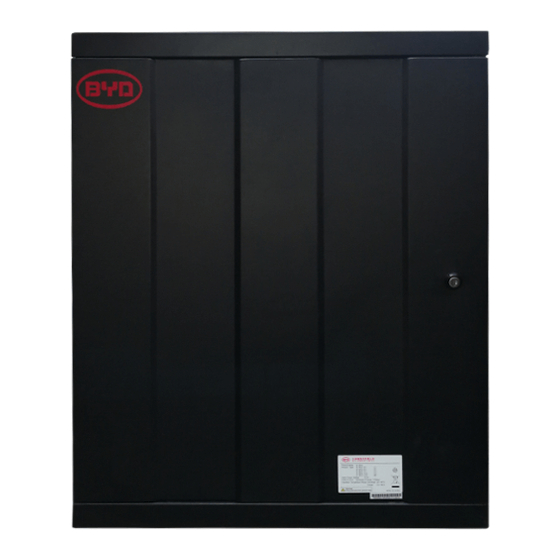
BYD Battery-Box PRO Series Service Manuallines
Hide thumbs
Also See for Battery-Box PRO Series:
- Installation guidance (46 pages) ,
- Quick reference manual (4 pages) ,
- User manual (15 pages)
Table of Contents
Advertisement
Quick Links
BYD Battery-Box PRO
Service Guideline
Version 1.0
Valid for PRO 2.5-10.0 and PRO 13.8
Important:Theinstallationandallotherkindsofworksor measurementsincombinationwiththe Battery-Box
are only allowed by professional and qualified electricians.
This manual is a shortened assistance for the installation / service of the Battery-Box PRO and does not replace
www.alpspower.com.au
the original manual, which can be found on
or www.byd.com. The installation must
be carried out by a trained and qualified electrician. Attention: High Voltage! Improper handling can cause danger
and damage.
Advertisement
Table of Contents

Summary of Contents for BYD Battery-Box PRO Series
- Page 1 This manual is a shortened assistance for the installation / service of the Battery-Box PRO and does not replace www.alpspower.com.au the original manual, which can be found on or www.byd.com. The installation must be carried out by a trained and qualified electrician. Attention: High Voltage! Improper handling can cause danger and damage.
-
Page 2: Table Of Contents
CONTENT CONTENT 1. CHECK INSTALLATION 1.1 System Components and general protection mechanisms 2. ERROR ANALYSIS 2.1 Installation or commissioning issues 2.2 Battery shutdown or inverter reports battery failure 2.3 Unusual behavior of a working system 3. SERVICE TASKS 3.1 Voltage measurement 3.2 Emergency charge 3.3 Battery information Query and Read Alarm history 3.4 Software update... -
Page 3: Check Installation
Please double check if your system and application is according to the Compatible Inverter List of BYD (available at www.alpspower.com.au) Please check the software version of the inverter is at least the minimum version stated in the compatible inverter list of BYD (available at www.alpspower.com.au) DC Power Cable Make sure that + and - are properly connected. -
Page 4: System Components And General Protection Mechanisms
1.1 System Components and general protection mechanisms The Battery consists of the BMU, Cables, BMS and Battery Cells. The BMU manages the communication between the inverter and all the batteries in the system. The BMU reports the safe working limits, battery status and battery alarms to the inverter. Therefore, if communication is not established correctly or lost the BMU will shutdown all the batteries. -
Page 5: Error Analysis
Blin BMU cannot Review in detail the commissioning steps in the inverter manual communicate with Confirm you are using the CAN cable recommended in the BYD inverter and inverter manual Exchange the cable between the BMU and Inverter BMU cannot... -
Page 6: Battery Shutdown Or Inverter Reports Battery Failure
2.2 Battery shutdown or inverter reports battery failure Yellow ARM light: Temporary issue → The system or the user can take action to correct it If the yellow light doesn’t disappear after a few minutes please review the electrical installation according to the below legend. Alarm: If the yellow ARM light is on, shortly press Reset (ON/OFF) Button and observe how often the LED blinks Cause... - Page 7 Red ERR light: Permanent issue → A component might have been damaged For 2.5 please see below table and report to your local service partner For 13.8 we need to confirm if the issue is in the battery, BMS or sampling cable before reporting to the local service partner.
-
Page 8: Unusual Behavior Of A Working System
2.3 Unusual behavior of a working system Case 1: Current too low If available please check the charge/discharge current limit from the inverter data. This value is provided by the battery to the inverter. This value may vary depending on the circumstances, such as SOC close to 0% or 100%, alarms or temperature below 12 degrees (See User manual for details on derating). -
Page 9: Service Tasks
3. SERVICE TASKS In some cases you might be asked to perform additional measurements or tasks to solve a service case 3.1 Voltage measurement ATTENTION: High voltage! The nominal voltage modules by 50V. Measure Voltage on BMS (should be about 50V): PRO 2.5-10.0 (B-PLUS 2.5): PRO 13.8 (BMS): For PRO 13.8: If the measured voltage deviates significantly from the nominal value, please measure the voltage... -
Page 10: Service Contact
4. SERVICE CONTACT Please note that this document is intended as a quick reference guide to quickly resolve common problems. Further information and detailed installation assistance can be found at www.alpspower.com.au To ensure a smooth process, please register yourself and the system under www.alpspower.com.au For further help please contact: ALPS Power...


Need help?
Do you have a question about the Battery-Box PRO Series and is the answer not in the manual?
Questions and answers