Table of Contents
Advertisement
Quick Links
Advertisement
Table of Contents

Related Manuals for Stabila REC 500 RG


Summary of Contents for Stabila REC 500 RG
- Page 1 How true pro’s measure REC 500 RG Operating instructions RED/GREEN BEAM...
-
Page 2: Table Of Contents
Contents Section Page • 1 Intended use • 2 Safety information • 3 Components of the unit • 4 Display elements • 5 Commissioning • 5.1 Battery insertion/replacement • 5.2 Switching the unit on • 5.3 Setting rotation/line mode • 5.4 Setting optical guidance •... -
Page 3: Intended Use
1 Intended use 2 Safety information Congratulations on the purchase of your STABILA measuring tool. The STABILA REC 500 RG Read the safety instructions and operating instructions through carefully. is an easy-to-use receiver for quickly locating red or green laser beams. The receiver functions with both pulse-modulated line lasers as well as rotation lasers. -
Page 4: Components Of The Unit
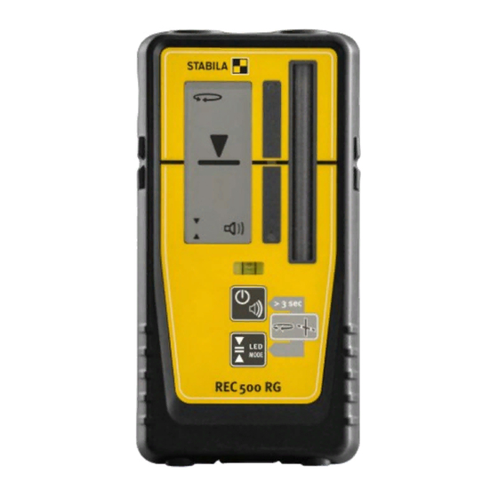
3 Components of the unit REC 500 RG (protected against water and dust in accordance with IP 67) Magnet Display – 1x on front, 1x on rear LED mode display Laser receiver “On line” marking Vial Retaining bracket mounting area... -
Page 5: Display Elements
4 Display elements Rotation mode display (14) Line mode display (15) “On line” position (16) (17) Display levels for height difference in relation to “On line” position 4-level accuracy adjustment (18) Battery charge (19) Acoustic guidance (20) -
Page 6: Commissioning
5 Commissioning 5.1 Battery insertion/replacement Open the battery compartment cover in the direction of the arrow, insert the new battery into the battery compartment according to the symbol. Suitable rechargeable batteries can also be used. LCD indicator: - Insert the new battery Used batteries should be disposed of at appropriate collection points. -
Page 7: Setting Optical Guidance
5.4 Setting optical guidance Holding the button for longer switches LED mode on or off. Visibility at greater distances or in lower levels of light can be improved using the LED display. LE D MODE > 3 s 5.5 Setting acoustic guidance The “Acoustic guidance”... -
Page 8: Functions
6 Functions 6.1 Visual guidance Height difference display The arrows indicate whether the receiver is too high or too low in relation to the laser beam. The line in the middle indicates the “On line” position of the receiver. In LED mode, 3 coloured LEDs also indicate the position. 6.2 Acoustic guidance The acoustic guidance is activated/deactivated using the “Acoustic guidance”... -
Page 9: Retaining Bracket
6.4 Retaining bracket Mounting: Use the locating pins and the mounting screw to align and mount the retaining bracket on the rear of the receiver. Reading reference... -
Page 10: Technical Data
7 Technical data Accuracy: Very fine: + 0.3 mm / ± 1/64” Fine: + 1 mm ± 3/64” Rough: + 2 mm ± 5/64” Very rough: + 5 mm ± 13/64” Receiving spectrum: 450–800 nm Acoustic signal: Loud: > 100 dBA Soft: 75 dBA Rotation laser speed:...
Need help?
Do you have a question about the REC 500 RG and is the answer not in the manual?
Questions and answers