
Subscribe to Our Youtube Channel
Related Manuals for NXP Semiconductors i.MX RT685


Summary of Contents for NXP Semiconductors i.MX RT685
- Page 1 NXP Semiconductors Document identifier: UM11159 User's Guide Rev. 0, March 20 2020 i.MX RT685 Evaluation Board...
-
Page 2: Table Of Contents
7.8 DMIC............................25 Chapter 8 Expansion connectors.................27 8.1 PMod connector........................27 8.2 Arduino connector........................27 Chapter 9 Other board features................30 9.1 MIMXRT685-EVK ADC references and inputs................30 i.MX RT685 Evaluation Board, Rev. 0, March 20 2020 User's Guide 2 / 31... -
Page 3: Chapter 1 Introduction
Introduction The i.MX RT685 Evaluation Board (part number MIMXRT685-EVK) is designed for customers to evaluate the i.MX RT685 MCU. It can be used with a range of development tools, including NXP’s MCUXpresso IDE. This User Manual describes Revision E of the board with B0 silicon. - Page 4 • Stereo NXP TFA9894 digital amplifiers, with option for external +5V power for higher performance speakers • Support for up to eight off-board digital microphones via 12-pin header • Two on-board DMICS i.MX RT685 Evaluation Board, Rev. 0, March 20 2020 User's Guide 4 / 31...
-
Page 5: Chapter 2 Board Layout And Settings
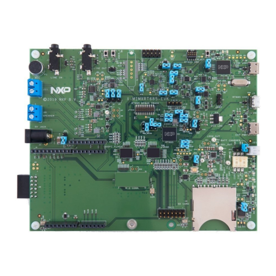
Board layout and settings Figure 2 shows the layout of the board (top side), indicating location of the connectors and buttons. Figure 2. i.MX RT685 EVK connectors, LEDs, buttons and headers Table 1 provides a description of connectors, LEDs and buttons. - Page 6 1.8V (default SW2_OUT) SD/eMMC Card socket. SD/eMMC card slot PMod/Host connector. This PMod connector connector provides access to the Table continues on the next page... i.MX RT685 Evaluation Board, Rev. 0, March 20 2020 User's Guide 6 / 31...
- Page 7 PMIC (PCA9420) SW1, SW2, LDO1 and LDO2. U40, U41 On-Board DMICs. On-board DMIC U108 pSRAM Schematic Figure 3 shows location of jumpers and headers. i.MX RT685 Evaluation Board, Rev. 0, March 20 2020 User's Guide 7 / 31...
- Page 8 Debug Probe. Open Schematic Jumper open (default) the i.MX RT685 Target SWD interface enabled. Normal operating mode where the Table continues on the next page... i.MX RT685 Evaluation Board, Rev. 0, March 20 2020 User's Guide 8 / 31...
- Page 9 +5V supply. Install in position 1-2 to JP11 Schematic draw digital amplifier supply from J6 (Rev E) power connector, or in Table continues on the next page... i.MX RT685 Evaluation Board, Rev. 0, March 20 2020 User's Guide 9 / 31...
- Page 10 This jumper Measuring MIMXRT685-EVK JP20 Closed is provided for optional insertion of an device supply current ammeter to measure supply current Table continues on the next page... i.MX RT685 Evaluation Board, Rev. 0, March 20 2020 User's Guide 10 / 31...
- Page 11 Header for access to I3C port. Note I3C header that this port is also shared with the Table continues on the next page... i.MX RT685 Evaluation Board, Rev. 0, March 20 2020 User's Guide 11 / 31...
- Page 12 RT685 (and other devices sharing this reset). Footprint-only for Trace Mictor 38 Adapter gives you the ability to Schematic perform trace. i.MX RT685 Evaluation Board, Rev. 0, March 20 2020 User's Guide 12 / 31...
-
Page 13: Chapter 3 Getting Started
When the board is used for the first time, it is recommended to force the i.MX RT685 target into a known state by performing an ISP boot before attempting to run your first example code. - Page 14 4. Connect the i.MX RT685 board to the USB port of your host computer, connecting a micro USB cable to connector J5 (Link USB). Allow about 30 seconds for the Link2 devices to enumerate for the first time. It is not necessary to check the Hardware Manager.
-
Page 15: Chapter 4 On-Board (Link2) Debug Probe
In order to correctly install and use the Link2 device on the i.MX RT685 EVK (required for any debugging purpose) for Windows 7 (or later) host computers, install the drivers first. These drivers will automatically be installed when MCUXpresso IDE has already been installed. -
Page 16: Vcom Port
• if the Debug Probe has been configured for DFU boot (JP1) installed at power up and MCUXpresso IDE has booted it (by starting a debug session). i.MX RT685 Evaluation Board, Rev. 0, March 20 2020 User's Guide 16 / 31... -
Page 17: Chapter 5 Board Power
1.8 V LDO1_OUT VDD_A0 VDDIO_2 1.5 - 2.1 V/2.7 - 3.3 V 3.3 V LDO2_OUT (JP12, 2-3) VDDIO_1 PMIC is configured via I C and external pins. i.MX RT685 Evaluation Board, Rev. 0, March 20 2020 User's Guide 17 / 31... - Page 18 Table 4. PMIC pins PMIC IMXRT685 PMIC_I2C_SCL PMIC_I2C_SDA MODESEL0 PMIC_MODE0 MODESEL1 PMIC_MODE1 PMIC_IRQ_N SYSREST RESET SW4 (JP16, 1-2) For further information, please refer to the board schematic. i.MX RT685 Evaluation Board, Rev. 0, March 20 2020 User's Guide 18 / 31...
-
Page 19: Chapter 6 Board Serial Connections
The MIMXRT685-EVK provides a Flexcomm interface (J47) with up to eight configurable universal serial interface modules. Each module can be configured as: USART, I C Bus, SPI Interface or I2S interface for digital audio. i.MX RT685 Evaluation Board, Rev. 0, March 20 2020 User's Guide 19 / 31... - Page 20 NXP Semiconductors Board serial connections Figure 4. i.MX RT685 EVK Flexcomm pinout i.MX RT685 Evaluation Board, Rev. 0, March 20 2020 User's Guide 20 / 31...
-
Page 21: Additional Expansion Header
Pin 2 P2_13 Pin 3 P0_3 Pin 4 P2_12 Pin 5 P0_4 Pin 6 P0_13 Pin 7 P0_12 Pin 8 P2_15 Pin 9 P2_14 Pin 10 P0_11 i.MX RT685 Evaluation Board, Rev. 0, March 20 2020 User's Guide 21 / 31... -
Page 22: Chapter 7 On-Board Peripherals
, the audio AMP operates at either 1.8 V or 3.3 V. A level shifter (U34) is added. SW2_OUT Table 7. Digital audio amplifier port connections Circuit reference Port I2C SDA P2_30 I2C SCL P2_29 Table continues on the next page... i.MX RT685 Evaluation Board, Rev. 0, March 20 2020 User's Guide 22 / 31... -
Page 23: Sd/Emmc Card Slot
) buttons are intended for user application use. These buttons pull ports low when the button is P1_1 P0_10 pressed. 100 kΩ resistors are used to pull these two ports to when the buttons are not pressed. VDDIO1 i.MX RT685 Evaluation Board, Rev. 0, March 20 2020 User's Guide 23 / 31... -
Page 24: Isp Boot Config
7.6.2 Reset Pressing this button (SW3) will assert reset to the MIMXRT685-EVK, TFA9894 amplifiers, pSRAM and OctalSPI Flash. If you want to route the i.MX RT685 reset control signal to the standard Arduino reset pin, install JP14. NOTE The Debug Probe (LPC4322) is not reset when this button is pressed. -
Page 25: Dmic
These pins are shared with the External DMIC. By default, on-board DMICS are selected (see R379 and R380). For further details, refer to the board schematics. i.MX RT685 Evaluation Board, Rev. 0, March 20 2020 User's Guide 25 / 31... - Page 26 PDM_CLK01_Ext P2_16 (Not connected by default) PDM_DATA01_Ext P2_20 PDM_CLK23_A P2_17 PDM_DATA23_A P2_21 PDM_CLK45_A P2_18 PDM_DATA45_A P2_22 PDM_CLK67_A P2_19 PDM_DATA67_A P2_23 I2C SCL P0_11 I2C SDA P0_10 i.MX RT685 Evaluation Board, Rev. 0, March 20 2020 User's Guide 26 / 31...
-
Page 27: Chapter 8 Expansion Connectors
The connectors J27-J30 provide Arduino compatibility and access to several other signals for use in prototyping. Some ports used on these connectors are shared with other devices/connectors on the board. Refer to the schematic for further information. i.MX RT685 Evaluation Board, Rev. 0, March 20 2020 User's Guide... - Page 28 NXP Semiconductors Expansion connectors Figure 5. i.MX RT685 EVK Arduino J27 and J28 headers pinout i.MX RT685 Evaluation Board, Rev. 0, March 20 2020 User's Guide 28 / 31...
- Page 29 NXP Semiconductors Expansion connectors Figure 6. i.MX RT685 EVK Arduino J29 and J30 headers pinout i.MX RT685 Evaluation Board, Rev. 0, March 20 2020 User's Guide 29 / 31...
-
Page 30: Chapter 9 Other Board Features
(1.8 by default and it can be SW2_OUT regulated by the PMIC) and the negative reference to the ground. NOTE By default, both expansions (JP9 and JP10) are not populated. i.MX RT685 Evaluation Board, Rev. 0, March 20 2020 User's Guide 30 / 31... - Page 31 How To Reach Us Information in this document is provided solely to enable system and software implementers to use NXP products. There are no express or implied copyright licenses granted hereunder to Home Page: design or fabricate any integrated circuits based on the information in this document. NXP nxp.com reserves the right to make changes without further notice to any products herein.
Need help?
Do you have a question about the i.MX RT685 and is the answer not in the manual?
Questions and answers