Riello RS 34/M MZ Installation, Use And Maintenance Instructions
Forced draught gas burners, progressive two-stage or modulating operation
Hide thumbs
Also See for RS 34/M MZ:
- Quick start manual (8 pages) ,
- Installation, use and maintenance instructions (77 pages) ,
- Installation, use and maintenance instructions (72 pages)
Table of Contents
Advertisement
Available languages
Available languages
Installation, use and maintenance instructions
Instrucciones de instalación, montaje y funcionamiento
Instruções de instalação, uso e manutenção
Forced draught gas burners
GB
Quemadores de gas de aire soplado
E
Queimadores a gás com ar insuflado
PT
Progressive two-stage or modulating operation
Funcionamiento a dos llamas progresivas o modulante
Funcionamento a duas chamas progressivas ou modulante
CODE - CÓDIGO
3788710
3788711
3788810
3788811
3788840
3788841
MODEL - MODELO
RS 34/M MZ
RS 34/M MZ
RS 44/M MZ
RS 44/M MZ
RS 44/M MZ
RS 44/M MZ
TYPE - TIPO
874 T
874 T
875 T
875 T
875 T
875 T
2916360 (12) - 05/2017
Advertisement
Chapters
Table of Contents

Related Manuals for Riello RS 34/M MZ


Summary of Contents for Riello RS 34/M MZ
- Page 1 Progressive two-stage or modulating operation Funcionamiento a dos llamas progresivas o modulante Funcionamento a duas chamas progressivas ou modulante CODE - CÓDIGO MODEL - MODELO TYPE - TIPO 3788710 RS 34/M MZ 874 T 3788711 RS 34/M MZ 874 T 3788810 RS 44/M MZ...
-
Page 2: Table Of Contents
CONTENTS INFORMATION ABOUT THE INSTRUCTION MANUAL DECLARATION ........page 1 INTRODUCTION TECHNICAL DATA . -
Page 3: Declaration
The quality is guaranteed by a quality and management system certified in accordance with ISO 9001:2015. Manufacturer’s Declaration RIELLO S.p.A. declares that the following products comply with the NOx emission limits specified by German standard “1. BImSchV release 26.01.2010”. Product... -
Page 4: Technical Data
TECHNICAL DATA MODEL RS 34/M MZ RS 44/M MZ RS 44/M MZ TYPE 874 T 875 T 875 T OUTPUT MAX. 125 - 390 203 - 550 203 - 550 108 - 336 175 - 473 175 - 473 Mcal/h MIN. -
Page 5: Accessories
BURNER RS 34-44/M MZ Code 3010386 • KIT LONG HEAD BURNER RS 34/M MZ RS 44/M MZ Code 3010428 3010429 • KIT FOR LPG OPERATION: the kit allows the RS 34-44/M MZ burners to burn LPG. BURNER... -
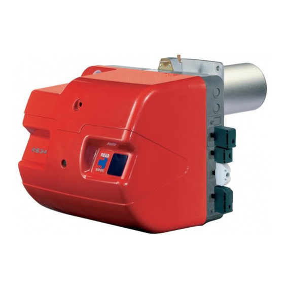
Page 6: Burner Description
4 - Screws to secure the burner flange to the boiler: M 8 x 25 1 - Thermal insulation screen 3 - Plugs for electrical connection RS 34/M MZ 442 508 216-351 140 1” (RS 34-44/M MZ single-phase) RS 44/M MZ 442 508 216-351 152 1”... -
Page 7: Firing Rates
• a MAXIMUM OUTPUT, selected within area A, • and a MINIMUM OUTPUT, which must not be lower than the minimum limit in the diagram: RS 34/M MZ = 45 kW RS 44/M MZ = 80 kW Important The FIRING RATE values have been obtained considering an ambient temperature of 20°C, an... -
Page 8: Gas Pressure
9.3 - 2 =7.3 mbar A pressure of 9.3 mbar (column 1) corresponds in the table RS 34/M MZ to an output of 260 kW. This value serves as a rough guide; the effective output must be measured at the gas meter. -
Page 9: Installation
The range of lengths available, L (mm), is as fol- lows: blast tube 10) RS 34/M MZ RS 44/M MZ • short D3834 • long For boilers with front flue passes 13) or flame... -
Page 10: Combustion Head Setting
COMBUSTION HEAD SETTING Installation operations are now at the stage where the blast tube and sleeve are secured to the boiler as shown in fig. (A). It is therefore par- ticularly easy to adjust the combustion head. Air adjustment (A - B) Rotate the screw 1)(A) until the notch on the lamina 2)(A) corresponds with the surface of the plate 3)(A). -
Page 11: Gas Feeding Line
GAS FEEDING LINE The fuel supply line must be installed by qualified personnel, in com- pliance with current standards and WARNING laws. Explosion danger due to fuel leaks in the presence of a flammable source. Precautions: avoid knocking, attri- tion, sparks and heat. Make sure that the fuel interception tap is closed before performing any operation on the burner. -
Page 12: Adjustment Prior To Ignition
ADJUSTMENTS PRIOR TO IGNITION MIN GAS PRESSURE SWITCH AIR PRESSURE SWITCH WARNING THE FIRST IGNITION MUST BE CARRIED OUT BY QUALIFIED PERSONNEL WITH THE RIGHT INSTRUMENTS. The adjustment of the combustion head, air, was described on page 8. In addition, the following adjustments must also be made: - open manual valves up-line from the gas train. -
Page 13: Burner Calibration
BURNER CALIBRATION The optimum calibration of the burner requires an analysis of the flue gases at the boiler outlet. Adjust successively: 1 - Output upon ignition (minimum) 2 - Max. burner output 3 - Intermediate outputs between Min. and Max. 4 - Air pressure switch 5 - Minimum gas pressure switch DETERMINATION OF OUTPUT UPON IGNI-... -
Page 14: Maximum Output
NOTE The servomotor follows the adjustment of cam III only when the angle of the cam is reduced. If it is necessary to increase the angle of the cam, you must first increase the angle of the servo- motor by means of the “output increase” key, then increase the angle of cam III, and finally bring the servomotor to the position of MIN out- put, with the “output reduction”... -
Page 15: Air Pressure Switch
4 - AIR PRESSURE SWITCH (A) AIR PRESSURE SWITCH 4)(A)p. 4 Adjust the air pressure switch after having per- formed all other burner adjustments with the air pressure switch set to the start of the scale (A). With the burner working at MIN output, insert a combustion analyser in the stack, slowly close the suction inlet of the fan (for example, with cardboard) until the CO value does not exceed... -
Page 16: Burner Operation
BURNER OPERATION STANDARD IGNITION (n° = seconds from the moment 0) BURNER START-UP (A) • 0s: Closure thermostat/pressure switch TL. • 2s: Start of electrical control box pro- gramme. Servomotor starts: rotate to the left by 90°, i.e. until the contact intervenes with cam I (D)p. -
Page 17: Final Checks
FINAL CHECKS (with the burner working): • disconnect a wire of the minimum gas pres- sure switch; • switch on the thermostat/pressure switch TL; • switch on the thermostat/pressure switch TS; the burner must stop. • disconnect the air adduction tube of the pres- sure switch;... -
Page 18: Switchboard Maintenance
TO OPEN THE BURNER (A): OPENING THE BURNER - Switch off the electrical power. - Remove the screw 1) and pull out the hood - Disengage the articulated coupling 3) from the graduated sector 4). - Remove the screw 5) only with the long head models;... - Page 19 BURNER START-UP CYCLE DIAGNOSTICS During start-up, the indications are explained in the following table: COLOUR CODE TABLE Sequences Colour code Pre-purging Ignition phase Operation, flame OK Operation with weak flame signal Electrical supply lower than ~ 170V Lockout Extraneous light Key to layout: Yellow Green...
-
Page 20: Fault - Probable Cause - Suggested Remedy
Signal Problem Possible cause Recommended remedy Once the pre-purging phase - The operation solenoid lets little gas through ..Increase 2 blinks and safety time have passed, - One of the two solenoid valves does not open..Replace the burner goes into lockout without the appearance of the... -
Page 21: Normal Operation / Flame Detection Time
NORMAL OPERATION / FLAME DETECTION TIME The control box has a further function to guarantee the correct burner operation (signal: GREEN LED permanently on). To use this function, wait at least ten seconds from the burner ignition and then press the control box button for a minimum of 3 seconds. After releasing the button, the GREEN LED starts flashing as shown in the figure below. -
Page 22: Appendix
The electrical wirings must be carried out in conform- ity with the regulations in force in the countries of des- tination, and by qualified personnel. Riello S.p.A. cannot accept any responsibility for mod- ifications or connections other than those shown in these diagrams. - Page 23 NOTES • The model RS 44/M MZ three-phase leaves the factory with an electrical supply setting of 400V. If 230V power supply is used, change the motor connection from star to delta and change the setting of the thermal cutout as well. •...
-
Page 24: Switchboard Layout
ÍNDICE INFORMACIONES SOBRE EL MANUAL DE INSTRUCCIÓN DECLARACIÓN........página 1 DATOS TÉCNICOS . -
Page 25: Declaración
La calidad está garantizada mediante un sistema de calidad y management certificado según ISO 9001:2015. Declaración del fabricante RIELLO S.p.A. declara que los siguientes productos respetan los valores limite de emisión de NOx establecidos por la normativa alemana “1. BImSchV revisión 26.01.2010”. - Page 26 DATOS TÉCNICOS MODELO RS 34/M MZ RS 44/M MZ RS 44/M MZ TIPO 874 T 875 T 875 T POTENCIA MAX. 125 - 390 203 - 550 203 - 550 108 - 336 175 - 473 175 - 473 Mcal/h MIN.
-
Page 27: Accesorios
QUEMADOR RS 34-44/M MZ Código 3010386 • KIT CABEZAL LARGO QUEMADOR RS 34/M MZ RS 44/M MZ Código 3010428 3010429 • KIT PARA FUNCIONAMIENTO CON GLP: el kit permite que los quemadores RS 34-44/M MZ funcionen con GPL. QUEMADOR... -
Page 28: Descripción Del Quemador
4 - Tornillos para fijar la brida del quemador a la caldera M 8 x 25 1 - Junta aislante 3 - Conectores para el cable de conexión RS 34/M MZ 442 508 216-351 140 1” (RS 34-44/M MZ monofásico) -
Page 29: Campos De Trabajo
• una POTENCIA MÁXIMA, situada en la zona A, • y una POTENCIA MÍNIMA, que no debe ser inferior al límite mínimo del gráfico: RS 34/M MZ = 45 kW RS 44/M MZ = 80 kW Atención El CAMPO DE TRABAJO se ha calculado con- siderando una temperatura ambiente de 20°C,... -
Page 30: Presión Del Gas
• Presión en la cámara de combustión= 2 mbar 9,3 - 2 =7,3 mbar A la presión de 9,3 mbar, columna 1, corres- ponde en la tabla RS 34/M MZ una potencia de 260 kW. Este valor sirve como primera aproximación; el real se determinará... -
Page 31: Instalación
Las longitudes, L (mm), disponibles son: Tubo llama 10) RS 34/M MZ RS 44/M MZ D3834 • corto • largo Para calderas con pasos de humos delanteros 13) o con cámara de inversión de llama, colocar... -
Page 32: Regulación Del Cabezal De Combustión
REGULACIÓN DEL CABEZAL DE COM- BUSTIÓN En este punto de la instalación, el tubo de llama y el soporte quemador se fijan a la caldera como se indica en la fig. (A). De esta manera se agiliza notablemente la la regulación del cabe- zal de combustión. -
Page 33: Línea Alimentación De Gas
LÍNEA ALIMENTACIÓN DE GAS La instalación de la línea de alimen- tación del combustible debe ser efectuada por personal habilitado, ATENCIÓN de acuerdo con las normas y las disposiciones de ley vigentes. Riesgo de explosión a causa de der- rame de combustible en presencia de fuentes inflamables. -
Page 34: Regulaciónes Previa Al Encendido
REGULACIÓNES PREVIA AL ENCENDIDO PRESOSTATO GAS DE MÍN. PRESOSTATO AIRE ATENCIÓN EL PRIMER ENCENDIDO DEBE SER REALI- ZADO POR PERSONAL CUALIFICADO Y CON LAS HERRAMIENTAS IDÓNEAS. La regulación del cabezal de combustión, aire y gas, ya se ha descrito en la pág 7. Efectuar, además, las siguientes regulaciones: - Abrir las válvulas manuales situadas antes de la rampa de gas. -
Page 35: Regulación Del Quemador
REGULACIÓN DEL QUEMADOR Para lograr una regulación óptima del quema- dor, es necesario efectuar un análisis de los gases de combustión en la base de la chimenea. Hay que regular en secuencia: 1 - Potencia de encendido (mínima) 2 - Potencia MÁX 3 - Potencias intermedias entre MÁX y MÍN 4 - Presostato aire 5 - Presostato gas de mínima... -
Page 36: Potencia Máx
NOTA El servomotor sigue la regulación de la leva III sólo cuando se reduce el ángulo de la misma. Si es necesario aumentar el ángulo de la leva, pri- mero hay que incrementar el ángulo del servo- motor mediante la tecla “aumento de potencia”, luego aumentar el ángulo de la leva III y por último volver a llevar el servomotor a la posición de potencia MÍN con la tecla “disminución de... -
Page 37: Presostato Aire
4 - PRESOSTATO AIRE (A) PRESOSTATO DE AIRE 4)(A)p. 4 Efectuar la regulación del presostato de aire, después de haber efectuado todas las demás regulaciones del quemador, con el presostato de aire ajustado al inicio de la escala (A). Con el quemador funcionando a la potencia MIN, introduzca en la chimenea un analizador de la combustión, cierre lentamente la boca de aspiración del ventilador (por ejemplo con un... -
Page 38: Funcionamiento Del Quemador
FUNCIONAMIENTO DEL QUEMADOR ENCENDIDO REGULAR (n° = segundos desde el instante 0) PUESTA EN MARCHA DEL QUEMADOR • 0s: Cierre termostato/presostato TL. • 2s: Arranca el programa de la caja de con- trol eléctrica. Se pone en marcha el servomotor: gira 90°... -
Page 39: Controles Finales
CONTROLES FINALES (con el quemador en funcionamiento): • desconectar un cable del presostato gas de mínima; • abrir el termostato/presostato TL; • abrir el termostato/presostato TS; el quemador debe detenerse. • Desconectar el tubo de aducción aire en el presostato; •... -
Page 40: Mantenimiento Cuadro Eléctrico
PARA ABRIR EL QUEMADOR (A): APERTURA DEL QUEMADOR - Cortar la tensión. - Quitar el tornillo 1) y extraer la cubierta 2). - Soltar la rótula 3) del sector graduado 4). - Quitar el tornillo 5) sólo si el modelo es de cabezal largo, retrase aproximadamente 100 mm el quemador sobre las guías 6). - Page 41 DIAGNOSIS PROGRAMA DE ARRANQUE Durante el programa de arranque, las indicaciones se explican en la siguiente tabla: TABLA CÓDIGO COLOR Secuencias Código color Preventilación Fase de encendido Funcionamiento con llama ok Funcionamiento con señal de llama débil Alimentación eléctrica inferior a ~ 170V Bloqueo Luz extraña Leyenda:...
- Page 42 Señal Anomalía Causa probable Solución Superada la pre-ventilación y - La electroválvula de funcionamiento deja pasar ..Aumentarlo 2 parpadeos el tiempo de seguridad, el poco gas quemador se bloquea sin - Una de las dos electroválvulas no se abre... Sustituirlas aparecer la llama - Presión gas demasiado baja .
-
Page 43: Funcionamiento Normal / Tiempo De Detección Llama
Señal Anomalía Causa probable Solución Ningún parpadeo El quemador no arranca 38 - Falta tensión eléctrica ......Cerrar interruptores;... -
Page 44: Apéndice
Las conexiones eléctricas se deben realizar según las normas vigentes del país de destino y por personal cuali- ficado. Riello S.p.A. declina toda responsabilidad por modifica- ciones o conexiones diferentes de las indicadas en estos esquemas. Utilizar cables flexibles según norma EN 60 335-1. - Page 45 NOTAS • El modelo RS 44/M MZ trifásico sale de fábrica previsto para una alimentación eléctrica de 400V. Si la alimentación es a 230V, cambiar el conexionado del motor (de estrella a triángulo) y la regulación del relé térmico. • Los quemadores RS 34-44/M MZ han sido homologados para funcionar de modo intermitente. Ello significa que deben pararse “por Norma” al menos una vez cada 24 horas para permitir que la caja de control efectúe una verificación de la eficacia al arranque.
- Page 46 ÍNDICE INFORMAÇÕES DO MANUAL DE INSTRUÇÕES DECLARAÇÃO ........página 1 INTRODUÇÃO DADOS TÉCNICOS.
-
Page 47: Declaração
A qualidade é garantida mediante um sistema de qualidade e gestão certificado segundo ISO 9001:2015. Declaração do fabricante RIELLO S.p.A. declara que os seguintes produtos respeita os valores limite dos NOx impostos pela normativa alemã “1. BImSchV versão 26.01.2010”. Produto... -
Page 48: Dados Técnicos
DADOS TÉCNICOS MODELO RS 34/M MZ RS 44/M MZ RS 44/M MZ TIPO 874T 875T 875T POTÊNCIA MÁX. 125 - 390 203 - 550 203 - 550 108 - 336 175 - 473 175 - 473 Mcal/h MÍN. Mcal/h COMBUSTÍVEL GAS NATURAL: G20 - G21 - G22 - G23 - G25 - poder calorífico inferior... -
Page 49: Acessórios
QUEIMADOR RS 34-44/M MZ Código 3010386 • KIT CABEÇA COMPRIDA QUEIMADOR RS 34/M MZ RS 44/M MZ Código 3010428 3010429 • KIT PARA FUNCIONAMENTO COM GPL: o kit permite que os queimadores RS 34-44/M funcionem com GPL. QUEIMADOR... -
Page 50: Descrição Do Queimador
4 - Parafusos para fixar a flange do queimador à caldeira M 8 x 25 1 - Junta isolante 3 - Fichas para conexões eléctricas RS 34/M MZ 442 508 216-351 140 1” (RS 34-44/M MZ monofásico) 4 - Fichas para conexões eléctricas... -
Page 51: Campos De Trabalho
• uma POTÊNCIA MÁXIMA, localizada na zona A, • e uma POTÊNCIA MÍNIMA, que não deve ser inferior ao limite mínimo do gráfico: RS 34/M MZ = 45 kW RS 44/M MZ = 80 kW Atenção O CAMPO DE TRABALHO foi calculado à tem- peratura ambiente de 20 °C, à... -
Page 52: Pressão Do Gás
• Potência MÁX desejada: 260 kW • Gás natural G 20 PCI 9,45 kWh/Sm • Pressão do gás à potência de 260 kW, na tabela do RS 34/M MZ,coluna 1A = 7,3 mbar • Pressão na câmara de combustão =... -
Page 53: Instalação
Os comprimentos, L (mm), disponíveis são: tubo chama 10) RS 34/M MZ RS 44//M MZ • curto D3834 • longo Para caldeiras com passagens de fumos dian- teiras 13) ou com câmara de inversão de... -
Page 54: Regulação Do Cabeçal De Combustão
REGULAÇÃO DO CABEÇAL DE COM- BUSTÃO Neste ponto da instalação, o tubo de fogo e o suporte queimador fixam-se à caldeira como é indicado na fig. (A). A regulação do cabeçal de combustão pode ser realizada portanto de modo particularmente fácil. Regulação do ar (A - B) Rodar o parafuso 1)(A) até... -
Page 55: Linha De Alimentação Gás
LINHA ALIMENTAÇÃO DE GÁS A instalação da linha deve ser feita por pessoal habilitado, de acordo com o conteúdo do presente manual ATENÇÃO e em conformidade com as dispo- sições e normas vigentes. Risco de explosão devido ao vaza- mento de combustível na presença de fonte inflamável. -
Page 56: Regulação Prévia Ao Acendimento
REGULAÇÃO PREVIA AO ACENDIMENTO PRESSOSTATO GÁS DE MÍN. PRESSOSTATO AR ATENÇÃO O PRIMEIRO ACENDIMENTO DEVE SER EXE- CUTADO POR PESSOAL QUALIFICADO E DOTADO INSTRUMENTAÇÃO ADE- QUADA. A regulação do cabeçal de combustão, ar, já foi descrita na pág. 8. Efectuar, ainda, as seguintes regulações: - abrir as válvulas manuais localizadas antes da linha de gás. -
Page 57: Regulação Do Queimador
REGULAÇÃO DO QUEIMADOR Para conseguir uma óptima regulação do quei- mador, é necessário fazer uma análise dos gases de combustão na base da chaminé. Terá que se regular consecutivamente: 1 - Potência de acendimento (mínima) 2 - Potência MÁX 3 - Potências intermédias entre MÁX e MÍN 4 - Pressostato ar 5 - Pressostato gás de mínima DETERMINAÇÃO DA POTÊNCIA DE ACEN-... -
Page 58: Potência Máx
NOTA O servomotor segue a regulação da came III somente quando se reduz o ângulo da came. Se necessário aumentar o ângulo da came, deve-se primeiro aumentar o ângulo do servo- motor com a tecla "aumento de potência", depois aumentar o ângulo da came III e final- mente recolocar o servomotor na posição de potência MÍN com a tecla "diminuição de potên- cia". -
Page 59: Pressostato De Ar
4 - PRESOSTATO DE AR (A) PRESSOSTATO DE AR 4)(A)p. 4 Efectuar a regulação do pressostato de ar, depois de ter feito todas as restantes regula- ções do queimador, com o pressostato de ar ajustado ao início da escala (A). Com o queimador em função com a potência MIN, inserir um analisador da combustão no chaminé, fechar lentamente o canal de aspira-... -
Page 60: Funcionamento Do Queimador
FUNCIONAMENTO DO QUEIMADOR ACENDIMENTO NORMAL (n° = segundos a partir do instante 0) ARRANQUE DO QUEIMADOR (A) • 0s: Fechamento termóstato/pressostato TL. • 2s: Inicia o programa da caixa de con- trole. Entra em funcionamento o ser- vomotor: gira para a esquerda 90°, isto é, até... -
Page 61: Controlo Final
CONTROLO FINAL (com o queimador em fun- cionamento): • dsconectar um fio do pressostato gás de mínima; • abrir o termóstato/pressostato TL; • abrir o termóstato/pressostato TS; o queimador deve parar. • Desligar o tubo de adução ar ao pressostato; •... -
Page 62: Manutenção Quadro Eléctrico
PARA ABRIR O QUEIMADOR (A): ABERTURA DO QUEIMADOR - Cortar a corrente eléctrica. - Aliviar o parafuso 1) e extrair a cobertura 2). - Soltar a rótula 3) do sector graduado 4). - Tirar o parafuso 5) apenas no caso de mode- los com cabeça longa, atrasar o queimador nas guias 6) por cerca de 100 mm. - Page 63 DIAGNÓSTICO DO PROGRAMA DE ARRANQUE Durante o programa de arranque, as indicações são explicadas na seguinte tabela: TABELA CÓDIGO COR Sequências Código cor Pré-ventilação Fase de acendimento Funcionamento com chama ok Funcionamento com sinal de chama fraca Alimentação eléctrica inferior a ~ 170V Bloqueio Luz estranha Legenda:...
- Page 64 Sinal Anomalia Causa provável Solução Superada a pré-ventilação e - A electroválvula de funcionamento faz passar ..Aumentá-lo 2 sinais intermitentes o tempo de segurança, o pouco gás. queimador bloqueia-se sem - Uma das electroválvulas não se abre....Substituir que apareça a chama.
-
Page 65: Funcionamento Normal / Tempo De Observação Da Chama
Sinal Anomalia Causa provável Solução Nenhum sinal intermi- O queimador não arranca 38 - Falta corrente eléctrica ......Fechar interruptores Controlar ligações tente eléctricas... -
Page 66: Apêndice
As ligações eléctricas devem ser executadas conforme as normas em vigor do país de destino e por pessoal qualificado. Riello S.p.A. declina toda responsabilidade de modifi- cações ou conexões diferentes daquelas representa- das nestes esquemas. Usar cabos flexíveis conforme a norma EN 60 335-1: Todos os cabos a ligar ao queimador devem ser feitos passar pelos passacabos. - Page 67 NOTAS • O modelo RS 44/M MZ trifásico deixa a fábrica previsto para alimentação eléctrica 400V. Se a alimentação for de 230 V, alterar a ligação do motor (de estrela a triângulo) e a regulação do relé térmico. • Os queimadores RS 34-44/M MZ foram homologados para funcionamento intermitente. Isto significa que devem parar “por Norma” pelo menos uma vez cada 24 horas para permitir que a caixa de controlo faça uma verificação da eficácia ao arranque.
-
Page 68: Esquema Quadro Eléctrico
Electrical panel layout - Esquema cuadro eléctrico Esquema quadro eléctrico INDEX - ÍNDICE - ÍNDICE Indication of references - Indicación referencias Indicação das referências RMG/M operational layout - Esquema funcional RMG/M Esquema funcional RMG/M Operational layout - Esquema funcional Esquema funcional Electrical connections set by installer - Conexiones eléctricas a cargo del instalador Ligações eléctricas pelo instalador Electrical connections set by installer - Conexiones eléctricas a cargo del instalador... - Page 77 KEY TO ELECTRICAL LAYOUT LEYENDA ESQUEMAS ELÉCTRICOS Electrical control box Caja de control eléctrica Radio noise filter Filtro antiinterferencias radio Output power regulator RWF Regulador de potencia RWF Input under current 4...20 mA DC Entrada en corriente 4...20 mA DC Entrada en corriente 4...20 mA DC para modificar setpoint Input under current 4...20 mA DC to modify the setpoint...
- Page 78 LEGENDA ESQUEMAS ELÉCTRICOS Caixa de controlo eléctrica Filtro contra radio-interferências Regulador de potência RWF Entrada em corrente 4...20 mA DC Entrada em corrente 4...20 mA DC para modificação do ponto de referência remoto Componentes bordo queimadores Componentes bordo caldeira Sonda de pressão Sonda de pressão Potenciómetro ponto de referência remoto Sonda por termopar...
- Page 80 RIELLO S.p.A. I-37045 Legnago (VR) Tel.: +39.0442.630111 http:// www.riello.it http:// www.riello.com Subject to modifications - Con la posibilidad de modificación - Sujeito a modificações...
Need help?
Do you have a question about the RS 34/M MZ and is the answer not in the manual?
Questions and answers