Table of Contents
Advertisement
Advertisement
Table of Contents

Related Manuals for Riello RS 310/M MZ


Summary of Contents for Riello RS 310/M MZ
- Page 1 Installation, use and maintenance instructions Forced draught gas burners Modulating operation CODE MODEL TYPE 20068343 - 20068351 RS 310/M MZ 1142T 20061373 20068356 - 20068361 RS 410/M MZ 1143T 20067141 20068027 RS 510/M MZ 1144T 20066706 RS 610/M MZ 1145T...
- Page 2 Translation of the original instructions...
-
Page 3: Table Of Contents
Contents Declarations....................................3 Information and general warnings............................4 Information about the instruction manual ........................4 2.1.1 Introduction.................................. 4 2.1.2 General dangers................................4 2.1.3 Other symbols ................................4 2.1.4 Delivery of the system and the instruction manual...................... 5 Guarantee and responsibility............................5 Safety and prevention................................ - Page 4 Contents Burner start-up ................................28 Burner ignition................................28 Air / fuel adjustment ..............................28 6.6.1 Burner adjustment..............................29 6.6.2 Output upon ignition..............................29 6.6.3 Maximum output ................................29 6.6.4 Minimum output .................................30 6.6.5 Intermediate outputs ..............................30 Pressure switch adjustment ............................31 6.7.1 Air pressure switch - check CO..........................31 6.7.2 Maximum gas pressure switch...........................31 6.7.3...
-
Page 5: Declarations
The quality is guaranteed by a quality and management system certified in accordance with UNI EN ISO 9001. Manufacturer's Declaration RIELLO S.p.A. declares that the following products comply with the NOx emission limits specified by German standard “1. BIm- SchV revision 26.01.2010”. -
Page 6: Information And General Warnings
Information and general warnings Information and general warnings Information about the instruction manual 2.1.1 Introduction WARNING: MOVING PARTS The instruction manual supplied with the burner: This symbol indicates that you must keep limbs ➤ is an integral and essential part of the product and must not away from moving mechanical parts;... -
Page 7: Delivery Of The System And The Instruction Manual
Information and general warnings 2.1.4 Delivery of the system and the instruction ➤ The system supplier must carefully inform the user about: – the use of the system; manual – any further tests that may be required before activating the When the system is delivered, it is important that: system;... -
Page 8: Safety And Prevention
Safety and prevention Safety and prevention Introduction The burners have been designed and built in compliance with the type and pressure of the fuel, the voltage and frequency of the current regulations and directives, applying the known technical electrical power supply, the minimum and maximum deliveries for rules of safety and envisaging all the potential danger situations. -
Page 9: Technical Description Of The Burner
Voltage of auxiliaries: 230/50/60 230V / 50-60Hz 110/50/60 110V / 50-60Hz 3/400/50 230/50/60 BASIC DESIGNATION EXTENDED DESIGNATION Models available Designation Voltage Start-up Code RS 310/M MZ 3/400/50 Star/Triangle 20061373 3/230/50 Direct 20068343 3/400/50 Direct 20068351 RS 410/M MZ 3/400/50 Star/Triangle 20067141... -
Page 10: Technical Data
Technical description of the burner Technical data Model RS 310/M MZ RS 410/M MZ RS 510/M MZ RS 610/M MZ Type 1142T 1143T 1144T 1145T Power min - max 600/1300 ÷ 3900 800/2000 ÷ 4900 802/2200 ÷ 5520 820/2400 ÷ 6300... -
Page 11: Burner Categories - Countries Of Destination
Technical description of the burner DIRECT START UP Model RS 310/M MZ RS 410/M MZ Code 20068343 - 20068351 20068356 - 20068361 Main electrical supply 3 ~ 230V +/-10% 50 Hz 3N ~ 400V +/-10% 50 Hz 2900 2920 230/400... -
Page 12: Burner Weight
Technical description of the burner Burner weight The weight of the burner complete with its packaging is shown in Tab. F. Model RS 310/M MZ RS 410/M MZ RS 510/M MZ RS 610/M MZ Tab. F 20072000 Fig. 1 Maximum dimensions The maximum dimensions of the burner are given in Fig. -
Page 13: Firing Rates
1013 mbar (approx. 0 m limit of the diagram: a.s.l.), and with the combustion head adjusted as WARNING shown on page 21. Model RS 310/M MZ RS 410/M MZ RS 510/M MZ RS 610/M MZ Tab. H 20072012... -
Page 14: Test Boiler
Technical description of the burner Test boiler The burner/boiler combination does not pose any problems if the The firing rates were set in relation to special test boilers, accord- boiler is EC approved and its combustion chamber dimensions ing to EN 676 regulations. are similar to those indicated in the diagram (Fig. -
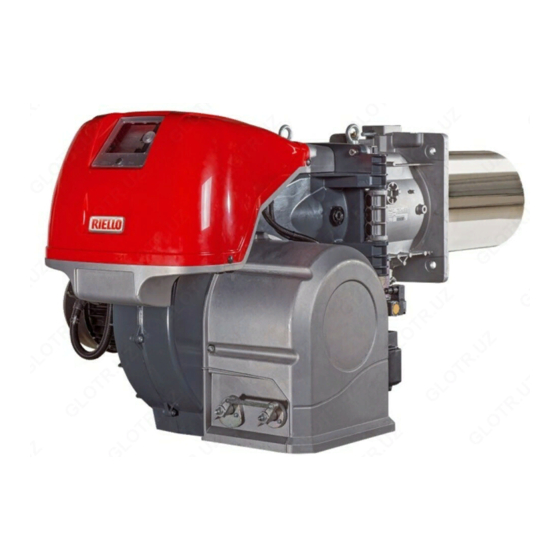
Page 15: Burner Description
Technical description of the burner 4.11 Burner description 20072012 20072012 Fig. 5 Lifting rings The burner can be opened to the right or to the left without links to the fuel supply side. Fan motor Air damper servomotor Combustion head gas pressure test point Combustion head To open the burner see section “Access to head Ignition electrode... -
Page 16: Electrical Panel Description
Technical description of the burner 4.12 Electrical panel description STAR/TRIANGLE START UP DIRECT START UP 20069356 Fig. 6 Ignition transformer Burner state indicator light and reset button. For further information see section “Burner ignition” on page 28 OFF-automatic-manual selector Electrical control box Power increase - power reduction selector Earth terminal Air pressure switch... -
Page 17: 4.13 Control Box Rmg88
The control box RMG88... is a safety device! WARNING Avoid opening or modifying it, or forcing its opera- tion. Riello S.p.A. cannot assume any responsibil- ity for damage resulting from unauthorised interventions! ➤ All interventions (assembly and installation operations, assistance, etc.) must be carried out by qualified personnel. -
Page 18: 4.14 Servomotor Sqm40
Technical description of the burner 4.14 Servomotor SQM40 ... Warnings To avoid accidents, material or environmen- tal damage, observe the following instruc- tions! WARNING Avoid opening, modifying or forcing the ser- vomotor. ➤ All interventions (assembly and installation operations, assistance, etc.) must be carried out by qualified personnel. ➤... -
Page 19: 4.15 Calibration Of The Thermal Relay
Technical description of the burner 4.15 Calibration of the thermal relay The thermal relay serves to avoid damage to the motor due to an excessive absorption increase or if a phase is missing. For calibration 2), see the table in the wiring diagram. To reset, in case of an intervention of the thermal relay, press the “RESET”... -
Page 20: Installation
Installation Installation Notes on safety for the installation After carefully cleaning all around the area where the burner will The installation of the burner must be carried out be installed, and arranging the correct lighting of the environ- by qualified personnel, as indicated in this manual ment, proceed with the installation operations. -
Page 21: Operating Position
The refractory can have a conical shape (minimum 60°). For boilers with front flue passes 1)(Fig. 14) or flame inversion RS 310/M MZ chamber, a protection in refractory material 5) must be inserted between the boiler fettling 2) and the flame funnel 4). -
Page 22: Access To Head Internal Part
Installation Access to head internal part The burner leaves the factory set for opening to the left, therefore maintaining the pin 1)(Fig. 15) in the housing. To open the burner towards the left, proceed as follows: A Remove the screw 6) releasing the tie-rod 7)(Fig. 15); B Disconnect the plug/socket 9)(Fig. -
Page 23: Gas Butterfly Valve
Installation Gas butterfly valve If necessary, replace the gas butterfly valve. The correct position is indicated in Fig. 17. Fig. 17 20078516 5.10 Combustion head adjustment Rotate the screw 1) until the notch you have found corresponds with the front surface of the screw itself. The combustion head is opened by turning the screw 1) anti- clockwise. - Page 24 Installation Below is a diagram (Fig. 20) that shows the recommended ad- NOTE: justment of the combustion head. Depending on the specific application, the adjustment can be modified. 20078016 No. Setpoint (air = gas) Max. burner output (kW) Fig. 20 20075344...
-
Page 25: Gas Feeding
Installation 5.11 Gas feeding Explosion danger due to fuel leaks in the pres- MBC “threaded” ence of a flammable source. Precautions: avoid knocking, attrition, sparks and heat. Make sure the fuel interception tap is closed be- fore performing any operation on the burner. The fuel supply line must be installed by qualified personnel, in compliance with current standards and laws. -
Page 26: 5.11.2 Gas Train
Installation 5.11.2 Gas train Approved according to standard EN 676 and provided separately Pay attention when handling the train: danger of from the burner. crushing of limbs. To select the correct gas train model, refer to the supplied “Burn- er-gas train combination” manual. Make sure that the gas train is properly installed by checking for any fuel leaks. -
Page 27: 5.11.4 Gas Pressure
Installation 5.11.4 Gas pressure 1 ∆ p (mbar) 2 ∆ p (mbar) Tab. K indicates the minimum pressure drops along the gas sup- G 20 G 25 G 20 G 25 ply line, depending on the maximum burner output. 1300 The values shown in Tab. -
Page 28: Electrical Wiring
Installation 5.12 Electrical wiring Notes on safety for the electrical wiring ➤ The electrical wiring must be carried out with the electrical supply disconnected. ➤ Electrical wiring must be made in accordance with the regulations currently in force in the country of destination and by qualified personnel. -
Page 29: Start-Up, Calibration And Operation Of The Burner
Start-up, calibration and operation of the burner Start-up, calibration and operation of the burner Notes on safety for the first start-up The first start-up of the burner must be carried out Check the correct working of the adjustment, com- by qualified personnel, as indicated in this manual mand and safety devices. -
Page 30: Burner Start-Up
Start-up, calibration and operation of the burner Burner start-up Turn off the thermostats/pressure switches and check the light Make sure that the lights or testers connected to signal 2) comes on (Fig. 6 on page 14). the solenoids, or the pilot lights on the solenoids Put the selector 1)(Fig. -
Page 31: Burner Adjustment
Start-up, calibration and operation of the burner 6.6.1 Burner adjustment Air adjustment The air is adjusted by varying the angle of cam I)(Fig. 28 on The optimum adjustment of the burner requires an analysis of page 27) and by using the selector 2)(Fig. 29 on page 28). To ad- flue gases at the boiler outlet. -
Page 32: Minimum Output
Start-up, calibration and operation of the burner 6.6.4 Minimum output 6.6.5 Intermediate outputs Min output must be selected within the firing rate range shown on Air adjustment Fig. 3 on page 11. No adjustment is required Press button 2)(Fig. 29 on page 28) “Diminishing output” and keep it pressed until the servomotor regains (Fig. -
Page 33: Pressure Switch Adjustment
Start-up, calibration and operation of the burner Pressure switch adjustment 6.7.1 Air pressure switch - check CO Adjust the air pressure switch (Fig. 33) after performing all other burner adjustments with the air pressure switch set to the start of the scale. -
Page 34: Operation Sequence Of The Burner
Start-up, calibration and operation of the burner Operation sequence of the burner 6.8.1 Burner start-up Normal ignition T0 : 0 s. - Closure of thermostat/pressure switch TL. (n° = seconds from instant 0) T1 : 2 s. - Start of electrical control box programme. 20073942 Fan motor starts up, servomotor starts up, the pre-purging phase starts. -
Page 35: Burner Start-Up Cycle Diagnostics
Start-up, calibration and operation of the burner Burner start-up cycle diagnostics 6.9.1 Resetting of control box and diagnostics use During start-up, indication is according to the colour code table (Tab. N). The control box features a diagnostics function through which any causes of malfunctioning are easily identified (indicator: RED Sequences Colour code... -
Page 36: Normal Operation / Flame Detection Time
Start-up, calibration and operation of the burner 6.10 Normal operation / flame detection time The control box has a further function to guarantee the correct After releasing the button, the GREEN LED starts flashing as burner operation (signal: GREEN LED permanently on). shown in: Tab. -
Page 37: Maintenance
Maintenance Maintenance Notes on safety for the maintenance The periodic maintenance is essential for the good operation, safety, yield and duration of the burner. Disconnect the electrical supply from the burner It allows you to reduce consumption and polluting emissions and by means of the main system switch. -
Page 38: Safety Components
Maintenance Combustion 7.2.3 Safety components If the combustion values measured before starting maintenance The safety components should be replaced at the end of their life do not comply with applicable legislation or do not indicate effi- cycle indicated in the following table. cient combustion, consult the Tab. -
Page 39: Faults - Possible Causes - Solutions
Faults - Possible causes - Solutions Faults - Possible causes - Solutions In the event the burner stops, in order to prevent In the event there are further lockouts or faults any damage to the installation, do not unblock the with the burner, the maintenance interventions burner more than twice in a row. - Page 40 Faults - Possible causes - Solutions Signal Problem Possible cause Recommended remedy 10 blinks The burner does not Incorrect electrical wiring Check switch on, and the lock- out appears The burner goes into Defective control box Replace lockout Presence of electromagnetic disturbances in the Filter or eliminate thermostat lines Presence of electromagnetic disturbance...
-
Page 41: A Appendix - Accessories
Appendix - Accessories Appendix - Accessories Analogue control signal converter kit Burner Type Code 0/2 - 10V All models 20074479 0/4 - 20mA Kit for modulating operation Burner Output regulator Code All models RWF 50.2 3-POINT OUTLET 20073595 All models RWF 55.5 COMPLETE WITH RS-485 INTERFACE 20074441 All models... -
Page 42: B Appendix - Electrical Panel Layout
Contents Indication of references Single line output diagram (RS 310/M MZ 230 V - Direct Start Up) Single line output diagram (RS 310/M MZ 400 V - Direct Start Up) Single line output diagram (RS 410/M MZ 230 V - Direct Start Up) - Page 43 Appendix - Electrical panel layout 20075344...
- Page 44 Appendix - Electrical panel layout 20075344...
- Page 45 Appendix - Electrical panel layout 20075344...
- Page 46 Appendix - Electrical panel layout 20075344...
- Page 47 Appendix - Electrical panel layout 20075344...
- Page 48 Appendix - Electrical panel layout 20075344...
- Page 49 Appendix - Electrical panel layout 20075344...
- Page 50 Appendix - Electrical panel layout 20075344...
- Page 51 Appendix - Electrical panel layout 20075344...
- Page 52 Appendix - Electrical panel layout & & 20075344...
- Page 53 Appendix - Electrical panel layout 20075344...
- Page 54 Appendix - Electrical panel layout 20075344...
- Page 55 Appendix - Electrical panel layout 20075344...
- Page 56 Appendix - Electrical panel layout 20075344...
- Page 57 Appendix - Electrical panel layout 20075344...
- Page 58 Appendix - Electrical panel layout 20075344...
- Page 59 Appendix - Electrical panel layout 20075344...
- Page 60 Appendix - Electrical panel layout 20075344...
- Page 61 Appendix - Electrical panel layout 20075344...
- Page 62 Appendix - Electrical panel layout 20075344...
- Page 63 Appendix - Electrical panel layout Wiring layout key Electrical control box Output power regulator RWF40 internal Input in current DC 0...20 mA, 4...20 mA Input in current DC 0...20 mA, 4...20 mA to modify re- mote setpoint Pressure probe Pressure probe Remote setpoint potentiometer Thermocouple probe Probe Pt100, 2 wires...
- Page 64 RIELLO S.p.A. I-37045 Legnago (VR) Tel.: +39.0442.630111 http:// www.riello.it http:// www.riello.com Subject to modifications...
Need help?
Do you have a question about the RS 310/M MZ and is the answer not in the manual?
Questions and answers