Riello RS 34/1 MZ Installation, Use And Maintenance Manual
Forced draught
Hide thumbs
Also See for RS 34/1 MZ:
- Installation, use and maintenance instructions (76 pages) ,
- Installation, use and maintenance instructions (77 pages)
Chapters
Table of Contents

Related Manuals for Riello RS 34/1 MZ


Summary of Contents for Riello RS 34/1 MZ
- Page 1 Installation, use and maintenance instructions 安装, 使用和维护说明书 Forced draught gas burners 强制通风燃气燃烧器 One-stage operation 一段火运行 编码 型号 类型 CODE - MODEL - TYPE - 20033785 RS 34/1 MZ 886 T 20033725 RS 44/1 MZ 873 T 20033803 (2) - 08/2011...
- Page 2 IDENTIFICATION The Identification Plate on the product gives the serial number, model and main technical and performance data. If the Identification Plate is tampered with, removed or missing, the product cannot be clearly identified, thus making any installation or maintenance work potentially dangerous. GENERAL WARNINGS The dimension of the boiler’s combustion chamber must respond to specific values, in order to guarantee a combustion with the lowest polluting emissions rate.
-
Page 3: Table Of Contents
INFORMATION ABOUT THE INSTRUCTION INDEX MANUAL TECHNICAL DATA ....... page 2 Structural versions . -
Page 4: Technical Data
TECHNICAL DATA MODEL RS 34/1 MZ RS 44/1 MZ TYPE 886 T 873 T OUTPUT 70 - 390 100 - 550 Mcal/h 60 - 336 86 - 473 FUEL NATURAL GAS: G20 - G21 - G22 - G23 - G25... -
Page 5: Accessories
If the burner is installed in places particularly subject to radio disturbance (emission of signals exceeding 10 V/m) owing to the presence of an INVERTER, or in applications where the length of the thermostat connections exceeds 20 metres, a protection kit is available as an interface between the control box and the burner. BURNER RS 34/1 MZ RS 44/1 MZ Code 3010386 •... -
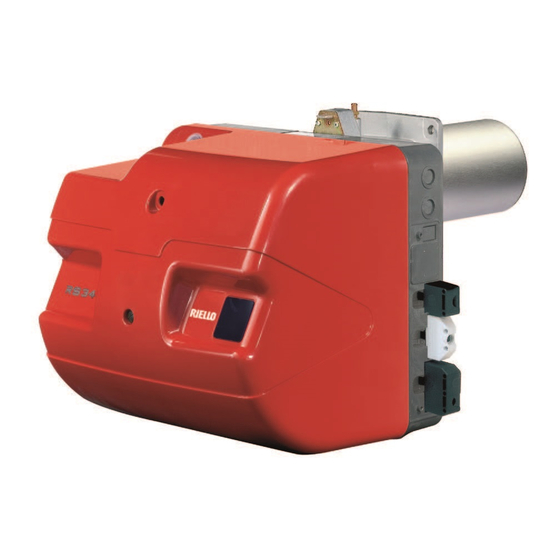
Page 6: Burner Description
15 Gas train connection flange 16 Boiler fixing flange 17 Flame stability disc 18 Flame inspection window 19 Motor capacitor (RS 34/1 MZ) 20 Control box with lockout pilot light and lock- out reset button 21 Plugs for electrical wiring... -
Page 7: Firing Rates
FIRING RATES (A) The burner output must be selected within the area of the adjacent diagrams. Attention the FIRING RATE value range has been obtained considering an ambient temperature of 20 °C, and an atmospheric pressure of 1013 mbar (approx. 0 m a.s.l.) and with the combustion head adjusted as shown on page 9. -
Page 8: Gas Pressure
• Natural gas G 20 PCI 9.45 kWh/Sm 100 1,0 • Pressure of the gas at an output of 250 kW, from 125 1,4 the table RS 34/1 MZ, column 1 =6.9 mbar • Pressure in combustion chamber = 2 mbar... - Page 9 p (mbar) RS 44/1 MZ Two-stage gas train MB-ZR 410 S2 MB-ZR 412 S2 MB-ZR 415 S2 MB-ZR 420 S2 (Rp 1") (Rp 1.1/4") (Rp 1.1/2") (Rp 2") 13,2 18,0 22,9 11,2 400 10,8 28,1 14,0 450 12,8 33,6 16,8 500 14,7 39,5 19,8...
-
Page 10: Installation
Any other position could compromise the correct working of the appliance. Installation 5 is forbidden, for safety reasons. RS 34/1 MZ BOILER PLATE (B) RS 44/1 MZ Pierce the closing plate of the combustion chamber, as in (B). The position of the threaded... -
Page 11: Combustion Head Setting
COMBUSTION HEAD SETTING Installation operations are now at the stage where the blast tube and sleeve are secured to the boiler as shown in fig. (A). It is therefore par- ticularly easy to adjust the combustion head. Air adjustment (A - B) Rotate the screw 1)(A) until the notch on the lamina 2)(A) corresponds with the surface of the plate 3)(A). -
Page 12: Gas Feeding Line
GAS FEEDING LINE • The gas train must be connected to the gas attachment 1)(A), using the flange 2), gasket 3) and screws 4) supplied with the burner. • The gas train can enter the burner from the right or left side, depending on which is the most convenient, see fig. -
Page 13: Adjustment Before First Firing
ADJUSTMENTS BEFORE FIRST FIRING MIN GAS PRESSURE SWITCH AIR PRESSURE SWITCH ATTENTION THE FIRST FIRING MUST BE CARRIED OUT BY QUALIFIED PERSONNEL WITH THE RIGHT INSTRUMENTS. Adjustment of the combustion head, and air and gas deliveries has been illustrated on page 9. In addition, the following adjustments must also be made: open manual valves up-line from the gas... -
Page 14: Burner Calibration
BURNER CALIBRATION The optimum calibration of the burner requires an analysis of the exhaust gases at the boiler outlet. Adjust successively: 1 - Maximum output; 2 - Air pressure switch; 3 - Minimum gas pressure switch. DETERMINATION OF OUTPUT UPON FIR- ING (MINIMUM) According to the regulation EN 676. -
Page 15: Air Pressure Switch
Note AIR PRESSURE SWITCH 4)(A)p. 4 Once you have finished adjusting maximum out- put, check firing once again: noise emission at this stage must be identical to the following stage of operation. If you notice any sign of pul- sations, reduce the firing stage delivery. 2 - AIR PRESSURE SWITCH (A) Adjust the air pressure switch after having per- formed all other burner adjustments with the air... -
Page 16: Burner Operation
BURNER OPERATION STANDARD FIRING (n° = seconds from the moment 0) BURNER START-UP (A) • Control device TL closes. After about 3s: • 0 s : The control box starting cycle begins. • 2 s : Fan motor starts. The air gate valve is set on maximum adjustment output. -
Page 17: Final Checks
FINAL CHECKS (with the burner working): • disconnect a wire of the minimum gas pres- sure switch; • switch on the thermostat/pressure switch TL; • switch on the thermostat/pressure switch TS; the burner must stop. • Disconnect the air adduction tube of the pres- sure switch;... - Page 18 BURNER START-UP PROGRAMME DIAGNOSTICS During start-up, the indications are explained in the following table: COLOUR CODE TABLE Sequences Colour code Pre-purging Firing phase Operation, flame OK Operation with weak flame signal Electrical supply lower than ~ 170V Lockout Extraneous light Key to layout: Yellow Green...
- Page 19 Signal Problem Possible cause Recommended remedy Once the pre-purging phase - The operation solenoid lets little gas through ..Increase 2 blinks and safety time have passed, - One of the two solenoid valves does not open..Replace the burner goes into lockout without the appearance of the...
-
Page 20: Normal Operation / Flame Detection Time
NORMAL OPERATION / FLAME DETECTION TIME The control box has a further function to guarantee the correct burner operation (signal: GREEN LED permanently on). To use this function, wait at least ten seconds from the burner ignition and then press the control box button for a minimum of 3 seconds. After releasing the button, the GREEN LED starts flashing as shown in the figure below. -
Page 21: Appendix
The electrical wirings must be carried out in conformity with the regulations in force in the countries of destination, and by qualified personnel. Riello S.p.A. cannot accept any responsibility for modifica- tions or connections other than those shown in these dia- grams. - Page 22 识别 产品铭牌上印有序列号、型号、主要技术及性能数据。如果铭牌被篡改、拆除或丢失,产品型号不容易识别, 安装或维修过程中会存在潜在危险。 通用警告 为了保证燃烧污染物排放降至最低,锅炉燃烧室的尺寸必须满足特定尺寸。 建议在给特殊锅炉选择燃烧器时,咨询我们的技术支持部门。 有资质人员是指那些经过专业培训机构培训合格的专业技术人员。 该燃烧器只能用于设计时指定的应用。 由于错误安装或错误调整,或不正确或不合理使用,或没有遵照随燃烧器附带的使用说明书来使用,或由无 资质人员操作等因素所造成的任何人、畜、财产损失,制造商概不负责。 用户告知 如果燃烧器在点火或运行中出现故障,燃烧器执行 “安全停机” ,会有红色 LED 指示灯指示燃烧器锁定。要 重新启动燃烧器,按一下复位按钮。燃烧器重新启动后,红色 LED 指示灯熄灭。 这个操作最多允许重复 3 次,如果 “安全停机”还是发生,请联系我们的技术支持部门。 基本安全规则 严禁未成年人和无资质人员操作此设备。 在安装燃烧器房间的通风孔,进气格栅,排气格栅上不允许覆盖衣物、纸张或其他任何东西。 非认证人员不允许维修燃烧器。 拉出或缠绕电源插头是危险的。 清洁燃烧器前要断开主电源。 不要使用易燃物来擦拭燃烧器 (如酒精、汽油等 )。 盖子可以用肥皂水擦拭。 不要在燃烧器上放置任何东西。...
- Page 23 说明书的相关信息 目录 技术数据 ........2 引言...
-
Page 24: 技术数据
技术数据 型号 RS 34/1 MZ RS 44/1 MZ 类型 886 T 873 T 出力 70 - 390 100 - 550 Mcal/h 60 - 336 86 - 473 燃料 天然气 : G20 - G21 - G22 - G23 - G25 - 净热值... - Page 25 配件 ( 可选 ): 无线电干扰保护套件 • 由于存在变换器,在将燃烧器安装于极易受无线电干扰 ( 信号发射超过 10 V/m) 的位置时,或在节温器连接长度超过 20 米的应用场合,提供一保 护套件,用作控制箱和燃烧器之间接口。 燃烧器 RS 34/1 MZ RS 44/1 MZ 代码 3010386 • 加长燃烧头 燃烧器 RS 34/1 MZ RS 44/1 MZ 代码 3010428 3010429 • LPG 组件 : 该组件允许 RS 34-44/1 MZ 燃烧 LPG 燃烧器...
-
Page 26: 燃烧器描述
将风门打开到燃烧器输送所需要的数值 . 12 压力测试点 13 进风口 14 燃气供气管道 15 燃气阀组连接法兰 16 锅炉固定法兰 17 稳焰盘 18 观火孔 19 电机电容 (RS 34/1 MZ) 20 带锁定指示灯及锁定复位按钮的控制盒 21 电缆插头 22 风门挡板 23 电离子探针电缆的插接口 注意: 如果控制盒 20)(A) 的报警指示灯亮 (红 色) ,表明燃烧器处于锁定状态。 按下按钮,保持 1 至 3 秒,使其复位。... -
Page 27: 出力图
出力图 燃烧器的出力大小必须在左图显示的区域 范围内。 注意 出力图的值在如下条件下测得:环境温度 20°C, 大气压力 1013 mbar ( 海拔大约 0m), 燃烧头设置如 9 页图示。 测试锅炉 根据 EN 676 规定,出力图依据特定测试锅 炉设定。图表 (B) 显示了测试锅炉燃烧室的 直径及长度。 例如 : 出力 350 Mcal/h: 直径 = 50 cm - 长度 1.5 m。 商用锅炉 如果锅炉符合 CE 标准且其炉膛尺寸基本符 合表... - Page 28 8.9 mbar 18,1 • 炉膛背压 2 mbar 26,4 13,2 8.9 - 2 = 6.9 mbar 36,6 18,0 在 RS 34/1 MZ 的表中压力 6.9 mbar ( 列 1) 对应的出力为 250 kW。 47,8 22,9 11,2 这个值只能作为参考;精确的出力值要根 400 10,8 59,9 28,1 14,0 据燃气计量表测量。...
- Page 29 p (mbar) 二段火燃气阀组 RS 44/1 MZ MB-ZR 410 S2 MB-ZR 412 S2 MB-ZR 415 S2 MB-ZR 420 S2 (Rp 1") (Rp 1.1/4") (Rp 1.1/2") (Rp 2") 13,2 18,0 22,9 11,2 400 10,8 28,1 14,0 450 12,8 33,6 16,8 500 14,7 39,5 19,8 550 16,7...
-
Page 30: 锅炉固定板
如图 (B)所示在锅炉板上钻孔。孔的位置 可以用随然烧器一起提供的隔热垫来标记 划线。 D455 燃烧头长度 燃烧头的长度选择应按照锅炉厂商提供的 说明书来选取,任何情况下,燃烧头的长度 必须大于锅炉前炉墙和炉衬的总厚度。 燃烧头的长度 L (mm) 如下所示: 燃烧头长度 9) RS 34/1 MZ RS 44/1 MZ • 标准 • 加长 对于带前烟箱 6) 或反转火焰的锅炉, 必须 在锅炉炉衬 7)和燃烧头 9)之间安装用保 温材料制作的防护衬 8)。防护衬的安装不 D7564 能妨碍燃烧头的移动。 对于带有前水冷壁的锅炉,除非锅炉厂商特 别要求,否则防护衬 7)-8)(C) 是不需要的。... - Page 31 燃烧头的设置 安装工作进行到这一步,燃烧头和套管已经 安装到锅炉上,如图 (A) 所示。接下来调整 燃烧头比较容易。 空气调节 (A - B) 旋转螺栓 1)(A) 直到指示杆 2)(A) 上的刻槽 与面板 3) (A) 的表面对齐。 例 RS 44/1 MZ 燃烧器,出力 = 300kW. 如图 (B) 所示,对于最大出力 300 kW,空 气应该调节到刻度 4。 注意: 如果炉膛背压为 0 mbar,空气的调节按图 (B) 中的虚线所示来调节。 中心风调节 (A - C) 在需要精确调试的应用中,可能需要按照图...
-
Page 32: 供气管路
燃气供气管路 • 用随燃烧器供应的法兰2) , 法兰垫3) 和螺 栓 4)将燃气阀组连接到燃气接口 1)(A) 上。 • 根据需要,燃气阀组可以从燃烧器的左右 两边连接,如图 (A)。为了确保燃气在 3 秒 钟的安全时间里能够到达燃烧头,燃气电 磁阀应该尽可能的靠近燃烧器。 燃气阀组 燃气阀组符合 EN 676 标准,与燃烧器分别 提供,订货代码由表 (C) 给出。表 (C) 的一 段火燃气阀组的功率最大可以到 550 kW, 只需要根据标准限制点火出力, 详见 12 页。 图例 1 - 燃气供气管 2 - 手动阀 D3839 3 - 减振接头... -
Page 33: 燃烧器点火
初次点火前调整 最小燃气压力开关 风压开关 警 告 告警 告 第一次点火必须由有资质人员利用专用 工具来完成。 燃烧头的调整,空气的调整已经在第 10 页 介绍。 另外,下面的这些调整也必须完成: - 打开燃气阀组前的手动阀; - 调节最小燃气压力开关至刻度 (A) 起始处 ; - 调节风压开关至刻度 (B) 起始处; - 排尽燃气管路中的空气; D3855 D3854 连续排放空气 (建议用一根软管接到室外 排放 ) 直到闻到燃气的味道。 - 在燃烧头燃气压力测点处安装一个压力 表如图 (C) 所示。 压力表的读数可以用来计算燃烧器的最 大出力的大概值,如第... -
Page 34: 燃烧器校准
燃烧器校准 燃烧器的最佳校准需要在排烟口使用烟气 分析仪进行烟气分析。 按如下顺序调整: 1 - 最大出力; 2 - 风压开关; 3 - 最小燃气压力开关; 点火出力确定 最小出力 燃烧器最大额定出力小于 120 kW 可以在最大额定运行出力下点火。例如: • 最大运行出力 : 120 kW • 最大点火出力 : 120 kW 燃烧器最大额定出力大于 120 kW 点火时的出力必须小于最大运行出力。 如果点火出力不超过 120 kW,无需调整。 如果点火出力超过 120 kW,点火出力根据 控制盒的安全时间 “ts”来确定: D593 "ts"... -
Page 35: 风压开关
注意 风压开关 ( 第 4 页 4)(A)) 一旦调整好最大出力,再次检查点火:点火 阶段的噪音必须和正常运行阶段的噪音接 近。如有异常噪音,可以适当减少点火出 力。 风压开关 在风压开关设置在量程开始位置 (A) 的前提 下完成燃烧器的基本调整后,再来调整风压 开关。 使燃烧器运行于最小出力状态,插入烟气分 析仪,慢慢的关小风机进风口(可以用一块 硬纸板)直到 CO 含量不超过 100 ppm。然 后顺时针转动旋钮,直到燃烧器到达锁定位 置。 检查刻度盘 (A) 上向上的那个箭头指示 的值。逆时针方向慢慢旋转旋钮直到这个值 与刻度盘 (A) 上那个向下的箭头对齐,这就 包含了压力开关动作滞后的量 ( 两个箭头之 间兰底白色标记显示的区域 )。 现在检查燃烧器能否正常启动: D3951 如果燃烧器再次锁定,再逆时针慢慢的旋转... -
Page 36: 燃烧器运行
燃烧器运行 正常点火 (n° = 从 0 秒开始后的秒数 ) 燃烧器启动 控制装置 TL 闭合 • 大概 3 秒钟后: 0 s :控制盒启动循环开始 • 2 s :风机电机启动。 • 风门打开到最大出力位置。 然后是预吹扫阶段。 • 43 s :点火电极打火花。 安全阀VS及调节阀VR的一段火阀 • VR1 打开。阀门 VR1 开始快速打 开,在较小出力下点火,点 A 所 示。然后调节阀 VR 慢慢开到最小 出力位置,燃气流量也慢慢平缓的... -
Page 37: 最终检查
最终检查 ( 燃烧器运行中进行 ): 断开最低燃气压力开关电缆; • • 断开温度 / 压力开关 TL • 断开温度 / 压力安全开关 TS ; 燃烧器必须停止 . • 断开风压开关的进风管; • 断开离子探针的电缆; 燃烧器必须停机并锁定 . 确认各个可调节设备上的锁紧装置已经紧 固。 维护 燃烧器需要定期维护,维护工作必须 具有专业技术资质并经由当地 由 相关部门认证的专业人员执行 。 定期维护对确保燃烧器的可靠性至关 重 要,避 免 燃 气 过 多 消 耗 及 过 多 污 染。... - Page 38 燃烧器启动程序诊断 启动过程中,指示灯的指示意义解释如下: 颜色代码表 顺序 颜色代码 预吹扫 点火阶段 运行火焰正常 弱火焰信号运行 电压低于 ~ 170V 锁定 外部光线 图例 : 不亮 黄色 绿色 红色 控制盒复位和使用诊断功能 红色 指示信号 控制盒提供了诊断功能, 因此可以很容易的识别可能存在的故障 ( 指示方式: )。 要使用此功能,待燃烧器进入安全状态 (锁定状态)后,至少等待 10 秒钟,然后按下复位按钮。 控制盒每隔 3 秒产生一个脉冲闪烁信号。 待观测到闪烁次数,并识别出可能的故障原因后,应按住复位安住复位安钮 1-3 秒钟,进行复位。 红色 指示灯亮 按复位按钮...
- Page 39 信号 故障 可能的原因 建议的弥补措施 闪烁 2 次 预吹扫和安全时间后燃 1 - 燃气阀组过气量太少 ....增加燃气量 烧器锁定并且没有火焰 2 - 两个电磁阀中的一个未打开... . . 更换 出现...
- Page 40 正常运行 监测到火焰的时间 控制盒有监控燃烧器正常运行的功能 ( 信号: LED 指示灯绿灯长亮 )。 要使用这个功能,燃烧器点火后等待十秒钟,按住控制盒的复位按钮保持 3 秒钟。 绿色指示灯开始闪烁,如下图所示 .: 绿色 按下按钮超过 3 秒 间隔 长亮至少等待 10 秒钟 信号 秒 信号 LED 指示灯间隔接近 3 秒闪烁。 闪烁的次数指示从燃气阀组开启后火焰探测监测到火焰的时间,如下图所示 : 信号 检测到火焰的时间 每次启动此数值都更新。 读取闪烁次数后,燃烧器需要按一下复位按钮重新启 闪烁 1 次 动。 0.4 秒 警告...
- Page 41 附录 电气连接 注意 电气接线必须由有相关资质的专业人员执行,对于不 按图接线或自行改变接线连接而造成的损失,利雅路 不负任何责任。 根据 EN 60 335-1 标准要求使用柔性电缆。 所有连接到燃烧器的电缆必须从导缆孔中穿过。 导缆孔可以有不同的用法;下面列出一种: RS 34-44/1 MZ 1-供温度 / 压力开关 TL 和单相电源的 7- 孔插座。 2- 供燃气阀组,燃气压力开关或检漏设备的 6- 孔插 座。 3-供温度 / 压力开关 TR 的 4- 孔插座 供远程复位用的 2- 孔插座 穿线管用 6 - 6A ( 捅破它,如果需要使用穿线管...
- Page 42 Electrical panel layout - 电气接线图 INDEX - 目录 Indication of references - 参考指示 RS 34/1 MZ Functional layout - 功能布局 RS 44/1 MZ RS 34/1 MZ Electrical wiring is the responsibility of the installation engineer - 安装方负责的电气接线 RS 44/1 MZ 参考指示...
- Page 43 RS 34/1 MZ...
- Page 44 RS 44/1 MZ...
- Page 45 RS 34-44/1 MZ...
- Page 46 KEY TO ELECTRICAL LAYOUT 电气图图例说明 – Electrical control box – 控制盒 – Radio noise filter – 抗电磁干扰的滤波器 – Components on burners – 燃烧器上的零件 – Components on boiler – 锅炉上的零件 – Capacitor – 电容 – Ionisation probe connector – 离子探针接头 – Remote lockout signalling –...
- Page 48 Registered Office - 公司注册所在地 : 生产场所 : Manufacturing site: RIELLO S.p.A. Riello Heating Equipment (Shanghai) CO., LTD Riello Heating Equipment (Shanghai) CO., LTD I-37045 Legnago (VR) No. 388, Jinbai Road - Jinshan Industrial Zone 利雅路热能设备 ( 上海 ) 有限公司 Tel.: +39.0442.630111 201506 - Shanghai 上海市金山工业区金百路...
Need help?
Do you have a question about the RS 34/1 MZ and is the answer not in the manual?
Questions and answers