Table of Contents
Advertisement
Advertisement
Table of Contents

Related Manuals for HydroLogic Hydroid


Summary of Contents for HydroLogic Hydroid
- Page 1 Reverse Osmosis User Manual 888-426-5644 info@hydrologicsystems.com...
- Page 2 This page intentionally left blank Hydroid – Series User Manual 04/19...
-
Page 3: Table Of Contents
PRESSURE FAULT ..........................30 PF AUTO RESET/PF RETRY ........................ 30 TANK FULL............................. 31 PRE-TREAT LOCKOUT ......................... 31 WATER QUALITY DISPLAY ........................31 MEMBRANE FLUSH ..........................31 WATER QUALITY SETPOINT ....................... 31 HYDROID FLOW DIAGRAM ..........................33 Hydroid – Series User Manual 04/19... - Page 4 The fitting can then be re-used. If the tube has been removed several times you may see score marks on the ends. This can lead to leaks so cut the end off the tubing totally square with a sharp blade using care. Hydroid – Series User Manual 04/19...
-
Page 5: Introduction
The Hydroid system features a robust, innovative design that requires no adjustments in the event of feed water quality or temperature variations. Your Hydroid system is a durable piece of equipment which, with proper care, will last for many years. Standard... -
Page 6: Safety
DO NOT SHUT DOWN THE SYSTEM FOR EXTENDED PERIODS. IT IS BEST TO RUN THE SYSTEM AS MUCH AS POSSIBLE ON A CONTINUOUS BASIS. ELEVATED LEVELS OF SEDIMENT IN FEED WATER WILL LEAD TO SHORTER LIFE FOR CARBON PRE-FILTER Hydroid – Series User Manual 04/19... -
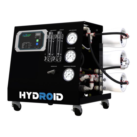
Page 7: Component Identification And Description
FLOW METER: CONCENTRATE (DRAIN) FLOW METER: PRODUCT (PURIFIED WATER) INLET PRESSURE FEED GAUGE PUMP PRESSURE GAUGE CONCENTRATE PRESSURE GAUGE PRODUCT 1/2"QC FITTING (PURIFIED WATER) CONCENTRATE 1/2"QC FITTING (DRAIN) INLET 1/2"QC FITTING (FEED) BLENDING VALVE (BLEND VALVE) Hydroid – Series User Manual 04/19... - Page 8 HIGH PRESSURE SWITCH, 40-60 PSI (HIGH PRESSURE SWITCH) 3/4 HP, GRUNDFOS PUMP, 110V, 60HZ, 1PH, 10.6 AMPS 2-WAY, SOLENOID VALVE, 110V, N/C FLOW CONTROL CONNECTOR (RECYCLE FLOW RESTRICTOR) FLOW CONTROL CONNECTOR (CONCENTRATE (DRAIN) FLOW RESTRICTOR) Hydroid – Series User Manual 04/19...
-
Page 9: Controller
TDS status on an easy-to-read 3-digit LED display. PRE-FILTRATION Hydroid systems come standard with a carbon pre-filter. Change the pre-filter when 75,000 gallons of purified water has been produced. Or, a 15 or more psi drop occurs on feed gauge, when compared to the initial startup reading. -
Page 10: Pump
PUMP The Hydroid system uses a multi-stage centrifugal stainless-steel pump. If any damage occurs to your system’s pump, a rebuild kit is available. Contact HydroLogic for parts and warranty. PUMP PRESSURE GAUGE The pump pressure gauge measures the pressure of the water as it enters the first membrane in the system. -
Page 11: System Installation Overview
Do not install system in direct sunlight, high intensity lights or subject the system to temperature extremes (see operating limits chart) and/or excess humidity. The Hydroid system should be secured in compliance with state and local regulations. -
Page 12: Concentrate Water (Drain) Connection
SOURCE. TANK Hydroid systems may be connected to a bladder tank or a storage tank with a float valve. The float valve shuts off the system when the tank is full and opens when the water level in the tank drops. - Page 13 Hydroid – Series User Manual 04/19...
-
Page 14: Feed Water And Operation Specifications
Low temperatures and feedwater quality, such as high TDS levels will significantly affect the systems production capabilities and performance. *If any of the feed water parameters are not within the given limits, consult HydroLogic for assistance. HIGHER TDS AND/OR LOWER TEMPERATURES WILL REDUCE THE SYSTEM’S PRODUCTION. -
Page 15: Design Basis And Design Notes
(see TCF Table on pg. 23). †††† PRODUCT (purified water) flow and maximum recovery rates are based on feedwater conditions as stated above. SYSTEM PURGING / INITIAL START–UP LEAVE THE SYSTEM UNPLUGGED FROM POWER UNTIL STEP 6 Hydroid – Series User Manual 04/19... - Page 16 Flush tubing (B) and then push system tubing (C) into carbon pre-filter port. Replace the red clip to lock system tubing to carbon pre-filter, shown in the picture below. For filter replacements, reverse this step. IMPORTANT: Keep black Flush tubing for future carbon pre-filter flush procedures. Hydroid – Series User Manual 04/19...
- Page 17 7. Let the system purge until no bubbles appear in CONCENTRATE (drain water - black tubing) flow meter (approx. 15 min). 8. When the Hydroid system has been purged of air, press the power button momentarily to turn off the purge feature. The Hydroid will turn off.
-
Page 18: Operating Do's And Don'ts
IF THE SYSTEM HAS AN ANTI-SCALANT FILTER (OPTIONAL HL 11595), AND IF THE PRODUCT WATER (PURIFIED WATER) IS USED AS POTABLE WATER, THE BLEND VALVE MUST REMAIN CLOSED. THIS IS TO AVOID INGESTION OF ANY CHEMICALS. Hydroid – Series User Manual 04/19... -
Page 19: Filter Removal And Replacement
(center hole) to hand-tightness. Pull the removal tool outward to remove the end plug from filter housing. Set the end plug aside in a clean area where the O-ring will not pick up dirt or debris. Hydroid – Series User Manual 04/19... - Page 20 If changing carbon filter, go to page 15, step 4 (filter flush). If replacing membrane, continue to step 14. 15) To start–up the system, please refer to the System Purging/Initial Start–Up section of this User’s Manual (pg. 15). Hydroid – Series User Manual 04/19...
-
Page 21: Membrane Elements
Rinse out the preservative before use. For membrane warranty details, contact HydroLogic for more information. If operating limits and guidelines given in this PRODUCT (purified water) specification sheet are not strictly followed, the warranty will be null and void. -
Page 22: Rejection, Recovery And Flow Rates
Percent of Recovery = (PRODUCT (purified water) Water Flow Rate / FEED (inlet) water flow rate) x 100 For Example, if the Hydroid makes 2.0 GPM PRODUCT (purified water) and has a FEED (inlet) flow of 2.66 GPM. (2.0 GPM PRODUCT (purified water) flow / 2.66 GPM FEED (inlet) flow) x 100 = 75% ALL FLOW RATES MUST BE EXPRESSED IN THE SAME UNITS, TYPICALLY GALLONS PER MINUTE (GPM). -
Page 23: Temperature Correction Factors For Membranes
Rated PRODUCT (purified water) Flowrate = 2 GPM @ 77°F Actual Water Temperature = 55°F Temperature Correction Factor @ 55°F = 1.541 PRODUCT (purified water) Flowrate @ 55°F = 2 GPM ÷ 1.541 = 1.297 GPM Hydroid – Series User Manual 04/19... - Page 24 Find the temperature correction factor (TCF) from the table below. Divide the rated PRODUCT (purified water) flow at 77°F by the temperature correction factor. The result is the PRODUCT (purified water) flow at the desired temperature (see example on previous page). Hydroid – Series User Manual 04/19...
-
Page 25: Operating Log
OPERATING LOG Hydroid – Series User Manual 04/19... -
Page 26: Preparing Unit For Storage Or Shipment
Membranes, sealing them in a plastic bag, and storing in a refrigerator. 3. If storing Membranes, performance cannot be guaranteed. During the shut-down period, the area must be kept frost-free, or the ambient temperature must not exceed 120°F (48.8°C) ambient. Hydroid – Series User Manual 04/19... -
Page 27: Troubleshooting
Defective controller board Operate NOT lit, board may need to be replaced. Use voltmeter to check inlet terminals for power to Wiring to pump controller board. If board has power, pump motor and motor wiring. Hydroid – Series User Manual 04/19... -
Page 28: Controller Specifications And Instructions
The Hydroid controller is a microprocessor-controlled system that can monitor pressure and level switches. The TDS monitor/controller with adjustable limit is an integral part of the Hydroid controller. The Hydroid controller displays system status and sensor and switch input status using a status LED and a 3-digit LED display. -
Page 29: Front Panel Controls And Indicators
POWER KEY - Places controller in operating or standby mode. SETPOINT KEY - Places display in mode to display current setpoint SP - Setpoint adjustment screw. If technical assistance is required, contact HydroLogic directly: Toll-free 888-426-5644 Hydroid – Series User Manual... -
Page 30: System Operation
“PF” will show on the water quality display and the status lamp will flash red. To clear the pressure fault, press the power key twice. Pressure Fault (PF) Retry Hydroid – Series User Manual 04/19... -
Page 31: Tank Full
The water quality setpoint can be adjusted from 0-999. If set to 999, the water quality lamp will always remain green. To set the water quality setpoint, press the Setpoint key. The display will Hydroid – Series User Manual 04/19... - Page 32 SP. Use a small screwdriver to adjust the SP adjustment to the desired setpoint value. Press the Setpoint key to return the display to the water quality display. Hydroid – Series User Manual 04/19...
-
Page 33: Hydroid Flow Diagram
HYDROID FLOW DIAGRAM Hydroid – Series User Manual 04/19... - Page 34 ELECTRICAL SCHEMATIC Hydroid – Series User Manual 04/19...
- Page 35 (3) a Return Goods Authorization Form; (4) a description of the suspected defects; (5) the serial number of the Manufacturer product alleged to be defective; and (6) a description of the type of water and Hydroid – Series User Manual 04/19...
- Page 36 CUSTOMER’S CUSTOMERS FOR ANY CONSEQUENTIAL, INCIDENTAL, OR ECONOMIC LOSS OR COMMERCIAL DAMAGE WHATSOEVER. REMEDIES HEREIN PROVIDED ARE EXPRESSLY MADE THE SOLE AND EXCLUSIVE REMEDIES FOR BREACH OF ANY WARRANTY OR OTHER OBLIGATION HEREUNDER EXPRESS OR IMPLIED OR FROM THE OPERATION OF LAW. Hydroid – Series User Manual 04/19...
- Page 37 Hydroid – Series User Manual 04/19...
Need help?
Do you have a question about the Hydroid and is the answer not in the manual?
Questions and answers