
Related Manuals for ESAB ESP-600C


Summary of Contents for ESAB ESP-600C
- Page 1 F-15-656 Jun., 2005 Installation, Operation, and Maintenance for the ESP-600C Plasma Power Source...
- Page 2 This manual is ESAB Part Number F15656 This manual is for the convenience and use of the cutting machine purchaser. It is not a contract or other obligation on the part of ESAB Cutting Systems. © © © © ESAB Cutting Systems, 2000...
-
Page 3: Table Of Contents
ESP-600C Plasma Power Source Table of Contents Page Section 1 Safety 1.1 Introduction 1.2 Safety Notations And Symbols 1.3 General Safety Information 1.4 Installation Precautions 1.5 Electrical Grounding 1.6 Operating A Plasma Cutting Machine 1.7 Service Precautions 1.8 Safety References Section 2 Description 2.1 General... - Page 4 ESP-600C Plasma Power Source Table of Contents Section 5 Maintenance 5.1 General 5.2 Cleaning 5.3 Fan Lubrication Section 6 Troubleshooting 6.1 General 6.2 Fault Indicators 6.3 Fault Isolation (Diagnostics) 4-10 6.3.1 Fans 6.3.2 Power not on or Low Voltage 6.3.3 Fault Light Illumination 6.3.4 Torch will not Fire...
-
Page 5: Esp-600C Plasma Power Source
ESP-600C Plasma Power Source Table of Contents Section 7 Replacement Parts 7.1 General 7.2 Ordering 7.3 Outside View - Front and Back 7.4 Front View With PCBs Exposed 7.5 Right Side View 7.6 Left Side View 7.7 Top View 10-11 7.8 Back Inside View... - Page 6 ESP-600C Plasma Power Source Table of Contents This page intentionally left blank.
-
Page 7: Section 1 Safety
1.1 Introduction The process of cutting metals with plasma equipment provides industry with a valuable and versatile tool. ESAB cutting machines are designed to provide both operation safety and efficiency. However, as with any machine tool, sensible attention to operating procedures, precautions, and safe practices is necessary to achieve a full measure of usefulness. -
Page 8: General Safety Information
SECTION 1 SAFETY 1.3 General Safety Information Machinery often starts automatically. WARNING This equipment moves in various directions and This equipment moves in various directions and This equipment moves in various directions and This equipment moves in various directions and speeds. -
Page 9: Installation Precautions
Follow these guidelines while installing machine: Follow these guidelines while installing machine: Follow these guidelines while installing machine: • Contact your ESAB representative before Contact your ESAB representative before Contact your ESAB representative before Contact your ESAB representative before installation. He can suggest certain precautions installation. -
Page 10: Electrical Grounding
SECTION 1 SAFETY 1.5 Electrical Grounding Electrical grounding is imperative for proper machine operation and SAFETY. Refer to this manual’s Installation section for detailed grounding instructions. Electric shock hazard. WARNING Improper grounding can cause severe injury or death. Improper grounding can cause severe injury or death. Improper grounding can cause severe injury or death. - Page 11 SECTION 1 SAFETY Hazardous voltages. Electric shock WARNING can kill. • Do NOT touch plasma torch, cutting table or cable Do NOT touch plasma torch, cutting table or cable Do NOT touch plasma torch, cutting table or cable Do NOT touch plasma torch, cutting table or cable connections during plasma cutting process.
- Page 12 SECTION 1 SAFETY Radiation hazard. WARNING Arc rays can injure eyes and burn Arc rays can injure eyes and burn skin. skin. Arc rays can injure eyes and burn Arc rays can injure eyes and burn skin. skin. • Wear correct eye and body protection. Wear correct eye and body protection.
- Page 13 SECTION 1 SAFETY Explosion hazard. WARNING • Certain molten aluminum-lithium (Al- Certain molten aluminum-lithium (Al- Certain molten aluminum-lithium (Al- Certain molten aluminum-lithium (Al-Li) alloys can Li) alloys can Li) alloys can Li) alloys can cause explosions when plasma cut OVER water. cause explosions when plasma cut OVER water.
-
Page 14: Service Precautions
SECTION 1 SAFETY 1.7 Service Precautions Hazardous voltages. Electric shock WARNING can kill. • Do NOT touch plasma torch, cutting table or cable Do NOT touch plasma torch, cutting table or cable Do NOT touch plasma torch, cutting table or cable Do NOT touch plasma torch, cutting table or cable connections during plasma cutting process. -
Page 15: Safety References
Systems for Welding and Cutting” - NFPA 51, National Fire Protection Association. • “Safety Precautions for Oxygen, Nitrogen, Argon, Helium, Carbon Dioxide, Hydrogen, and Acetylene,” Form 3499. ESAB Cutting Systems. Obtainable through your ESAB representative or local distributor. • "Design and Installation of Oxygen Piping Systems," Form 5110. - Page 16 SECTION 1 SAFETY This page intentionally left blank. 1-10 ESP-600Clasma Power Source ESP-600Clasma Power Source ESP-600Clasma Power Source ESP-600Clasma Power Source...
-
Page 17: Section 2 Description
The ESP power Source is designed for high speed plasma mechanized cutting applications. It can be used with other ESAB products such as the PT-15 and PT-600 torches along with the Smart Flow II, a computerized gas regulation and switching system. -
Page 18: Dimensions And Weight
SECTION 2 Description 2.3 Dimensions and Weight Front View OUTPUT AMPS MAIN CURRENT POWER VOLTS PILOT PANEL HIGH 6 0 0 C 6 0 0 C 6 0 0 C 6 0 0 C OVER TEMP ACTUAL AMPS REMOTE CONTACTOR PRESET AMPS FAULT POWER... -
Page 19: Section 3 Installation
Unit weighs over 2000 lbs. Use approved straps or cables in good condition. • Inspect for transit damage immediately upon receipt. • Remove all components from shipping container and check for loose parts in container. • Inspect louvers for air obstructions. ESP-600C Plasma Power Source... -
Page 20: Placement
Plan for top panel and side panels having to be Power removed for maintenance, cleaning and Source inspection. • Locate the ESP-600C relatively close to a properly fused electrical power supply. • Keep area beneath power source clear for cooling air flow. •... -
Page 21: Primary Power
SECTION 3 Installation 3.4.1 Primary Power ESP-600C is a 3-phase unit. Input power must be provided from a line (wall) disconnect switch that contains fuses or circuit breakers in accordance to local or state regulations. Recommended input conductor and line fuse sizes:... -
Page 22: Input Conductors
½" hardware before being attached to the ESP-600C. 3.4.3 Input Connection Procedure 1. Remove left side panel of the ESP-600C 2. Thread cables through the access opening in the rear panel. 3. Secure cables with a strain relief or conduit coupling (not supplied) at the access opening. -
Page 23: Output Connections
3.5.1 Output Cables (customer supplied) Choose plasma cutting output cables (customer supplied) on the basis of one 4/0 AWG, 600 volt insulated copper cable for each 400 amps of output current. Note: Do not use 100 volt insulated welding cable. ESP-600C Plasma Power Source... -
Page 24: Output Connection Procedure
Use Only One Power Source For Currents Below 100A. We recommend disconnecting the negative lead from the secondary power source when changing to currents below 100 amperes. This lead should be safely terminated (insulated) to protect against electric shock. ESP-600C Plasma Power Source... - Page 25 3 - 4/0 600V connection from 3 - 4/0 600V positive leads to secondary power source negative leads workpiece and insulate to to plumbing box (high freq. convert from two to one power generator) sources ESP-600C Plasma Power Source...
-
Page 26: System Interconnecting Block Diagram With Smart Flow
H-35 Torch (-) Pilot Arc Work (+) Smart Flow II WC-7 Water Cut Water Cooler Pump (for PT-15) Cooling Water To Torch Cooling Water Voltage From Torch Height Control Plasma Torch Bundle and Torch Earth Ground ESP-600C Plasma Power Source... - Page 27 Volt-Feedback Work piece voltage Process stop Interlocks Height Process on-off Current Ref Control Pilot arc High Freq Cutting Machine TORCH injection water Control Height Ref. PT-15 OR PT-600 Coolant to Current to Coolant From Work Piece ESP-600C Plasma Power Source...
- Page 28 SECTION 3 Installation This page intentionally left blank. 3-10 ESP-600C Plasma Power Source...
-
Page 29: Section 4 Operation
SECTION 4 Operation 4.1 Introduction The ESP-600C does not have an ON/OFF switch. The main power is controlled through the line(wall) disconnect switch. Do not operate the ESP-600C with WARNING Covers Removed. High voltage components are exposed increasing shock hazard. - Page 30 5 seconds and then reapplied. Current Dial (Potentiometer) Current Dial (Potentiometer) Current Dial (Potentiometer) Current Dial (Potentiometer) ESP-600C dial shown. ESP-600C has a range of 50 to 600 A. Used only in panel mode. Panel Remote Switch Panel Remote Switch Panel Remote Switch Panel Remote Switch Controls the location of current control.
- Page 31 Do not operate this equipment with covers Do not operate this equipment with covers Do not operate this equipment with covers removed. removed. removed. removed. ESP-600C Plasma Power Source ESP-600C Plasma Power Source ESP-600C Plasma Power Source ESP-600C Plasma Power Source...
-
Page 32: Sequence Of Operation
This feature uses 50% of the cutting current to start, dwell and then gradually (less than a second) achieve full current. The ESP-600C is factory shipped with this feature enabled. The default settings are: Minimum Start Current... - Page 33 Electric Shock Can Kill! WARNING Shut off power at the line (wall) disconnect before removing any covers or making any adjustments to the power source. ESP-600C Plasma Power Source ESP-600C Plasma Power Source ESP-600C Plasma Power Source ESP-600C Plasma Power Source...
-
Page 34: Enable/Disable Arc Initiation Timer
Switch #4 = 80 msec dwell time The default setting is with switch #3 on. 40 msec + 10 msec (minimum) = 50 msec ESP-600C Plasma Power Source ESP-600C Plasma Power Source ESP-600C Plasma Power Source ESP-600C Plasma Power Source... -
Page 35: Arc Initiation Controls
(after dwell ends) to full current. Factory default = 800 msec. Left position = 250 msec Center position = 800 msec Right Position = 1200 msec 10 MAX Start Current Pot Setting ESP-600C Plasma Power Source ESP-600C Plasma Power Source ESP-600C Plasma Power Source ESP-600C Plasma Power Source... -
Page 36: Esp-600C Plasma Power Source
SECTION 4 Operation 4.5 ESP-600C V-I Curves ESP-600C V-I CURVES = (80) x (V 427V Open Circuit (460V & 575V Models) 410V Open Circuit (400V Model) Output of Boost/Start Circuit Max Output Voltage @ Nominal Line OUTPUT CURRENT (Amperes) ESP-600C Plasma Power Source... -
Page 37: Section 5 Maintenance
Be sure to wear eye protection. Be sure to wear eye protection. Be sure to wear eye protection. Be sure to wear eye protection. ESP-600C Plasma Power Source ESP-600C Plasma Power Source ESP-600C Plasma Power Source ESP-600C Plasma Power Source... - Page 38 Electric Shock Hazard! WARNING Be sure to replace any covers removed during cleaning before turning power back ESP-600C Plasma Power Source ESP-600C Plasma Power Source ESP-600C Plasma Power Source ESP-600C Plasma Power Source...
-
Page 39: General
SECTION 6 Troubleshooting 6.1 General Electric Shock Can Kill! WARNING Do not permit untrained persons to inspect or repair this equipment. Electrical work must be performed by an experienced electrician. Stop Work Immediately If Power CAUTION Source Does Not Work Properly. Have only trained personnel investigate the cause. - Page 40 SECTION 6 Troubleshooting Fault Indicator (Front Panel) Illuminates when there are abnormalities in the cutting process or when the input voltage falls ±10% outside the normal value. Momentary illumination is normal. If continuously lit, check LEDs 3, 4, 5, 7, and 8 on PCB1 for further diagnosis.
- Page 41 SECTION 6 Troubleshooting Power Reset Fault Indicator (on front panel) Illuminates when a serious fault is detected. Input power must be disconnected for a least 5 seconds to clear this fault. Check PCB1 Red LEDs 6, 9, 10, 11, 12, and 13 if this fault is illuminated for further diagnosis.
-
Page 42: Fault Isolation (Diagnostics)
SECTION 6 Troubleshooting 6.3 Fault Isolation Many of the most common problems are listed by symptom. 6.3.1 Fans not working 6.3.2 Power not on 6.3.3 Fault Light Illumination 6.3.4 Torch won’t fire 6.3.5 Fusses Blown F1 and F2 6.3.6 Intermittent, Interrupted or Partial Operation 6.3.1 Fans Not Working Problem Possible Cause... -
Page 43: Fault Light Illumination
SECTION 6 Troubleshooting 6.3.3 Fault Light Illumination Problem Possible Cause Action Fault light illuminates at the end of Normal condition caused by Reprogram cutting process to terminating the arc by running the ensure arc is terminated only by cut but goes off at the start of the torch off the work or the arc being removing the “Contactor On”... - Page 44 SECTION 6 Troubleshooting Problem Possible Cause Action Output current of the right side Turn the output current down to LED 6 – (red) Right Over Current exceeds 200A because of operating 400A the power source over 400A. Note: Cutting at over 250A with a faulty See faulty left or right side If operation at 250A or less is left side (left side output = 0)
- Page 45 SECTION 6 Troubleshooting Problem Possible Cause Action Very high Output current Shorted IGBT Replace the pair of IGBTs containing the shorted IGBT accompanied by either a left or Current pot set too high Lower the current setting right over current (LED 6) Faulty left PWM/Drive PCB Replace left PWM/Drive PCB High remote current signal...
- Page 46 SECTION 6 Troubleshooting Problem Possible Cause Action LED 12 – (red) Left –12V Loose or unplugged P1 connector at Secure P1 connector the left PWM/Drive PCB Missing Loose or unplugged P10 connector Secure P10 connector at PCB1 Faulty left PWM/Drive PCB Replace left PWM/Drive PCB P/N 38030 LED 12 –...
-
Page 47: Torch Will Not Fire
SECTION 6 Troubleshooting 6.3.4 Torch Will Not Fire Problem Possible Cause Action Main Arc Transfers to the work Panel/Remote switch in “Remote” Place Panel/Remote switch in with a short “pop”, placing only a with no remote control of the “Panel” position small dimple in the work. -
Page 48: Fuses 1 And 2 Blown
SECTION 6 Troubleshooting 6.3.5 Fuses F1 and F2 Blown Problem Possible Cause Action Fuses F1 and F2 blown. Process controller ignites pilot arc Process controller must allow at too soon after providing the least 300MS to lapse between “Contactor On” signal the application of the “Contactor On”... - Page 49 SECTION 6 Troubleshooting Problem Possible Cause Action Works OK at 250A or less- Over Loose or unplugged connector at Secure connector current – Faulty Right Side Right PWM/Drive PCB (PCB3) Faulty Right PWM/Drive PCB Replace right PWM/Drive PCB P/N 38030 Check voltage between P5-1 and Replace control transformer T7 P5-2 at the right PWM/Drive PCB...
- Page 50 SECTION 6 Troubleshooting Problem Possible Cause Action Output current is unstable and Place the PANEL/REMOTE Fix the remote current control drifts above or below the setting. switch in the “PANEL” position. signal to operate the Adjust current control pot. If PANEL/REMOTE switch in the current no longer drifts, the “PANEL”...
-
Page 51: Testing And Replacing Components
• If a PC board is found to be a problem, check with your ESAB distributor for a replacement. Provide the distributor with the part number of the board as well as the serial number of the power source. -
Page 52: Power Rectifiers
SECTION 6 Troubleshooting 6.4.1 Power Rectifiers Power Rectifiers – Procedure to access behind the front panel 1. Remove top cover and side panels 2. Locate and disconnect plug in rear of ammeter (white plug with one red and one black wire) 3. -
Page 53: Positive Plate
SECTION 6 Troubleshooting 1. Check ohms between NEG Plate and BR “A” Bus. A reading of 2 ohms or less indicates one NEG Plate Diode Rectifier or more shorted diodes. Replace all Diodes on NEG Plate. “C” bus 2. If fuses F8 and/or F9 were open in the first step, “A”... -
Page 54: Freewheeling Diodes And Igbts
SECTION 6 Troubleshooting 6.4.2 Troubleshooting Freewheeling Diode and IGBTs Freewheeling Diodes and IGBTs 1. Remove top cover. 2. Remove “incoming” bus bars. 3. Remove PCB2 and PCB3 from IGBTs. (PC boards are held in place by four screws each.) After PCB2 and/or PCB3 have been CAUTION removed, protect against electrostatic damage. - Page 55 SECTION 6 Troubleshooting 4. Remove bus bars between capacitor banks, IGBTs and freewheeling diodes. View of freewheeling diodes and capacitor banks with bus bars removed. (PCB2 and PCB3 are PCB3 PCB2 shown still in place) Failure To Route Leads Properly Can Lead To CAUTION Failure Of Freewheeling Diodes.
-
Page 56: Power Shunt Installation
SECTION 6 Troubleshooting Some power sources may contain snubber NOTICE resistors and capacitors in a molded module similar in size and mounting to the free wheeling diode modules. These snubber modules utilize two conductive straps. One strap attaches to the free wheeling diode terminal #1 and the other to terminal #3. -
Page 57: Procedure For Verifying Calibration Of Digital Meters
SECTION 6 Troubleshooting Clear Insulation • It is important to have the barrels of the black and clear insulated wires, from the three lead cable, be pointing in opposite directions. Three Leads Two Leads • The third wire attaches to the bus bar on the left with the shunt mounting hardware. - Page 58 SECTION 6 Troubleshooting 6.5 ESP-400C Schematic Diagrams - Drawing 1 - Part1 Descrip Descrip Descrip M1,2 Motor ,fan 1/3 hp C14-16 Capacitor .033uf 630v Capacitor 5uf 600vdc Motor, fan 230v 50/60hz D19,20,23 Module diode rectifier 630v C13,15,17 Capacitor .033uf 630v Transformer main R12,13 Resistor 8ohm 300w...
- Page 59 SECTION 6 Troubleshooting Schematic Diagram - Drawing 1 – Part2 3b 4b Capacitor .033uf 630v C41-43,44 Capacitor .01uf 125vdc Resistor 10k 8w R4,6,8,9 Resistor 10ohm 50w D29,30 Rectifier silicone reverse 85A Capacitor 60uf 370v D1,3,5,6 Module diode dual 100A 600V D31,32 Rectifier silicone forward 85A C39,40...
- Page 60 SECTION 6 Troubleshooting Schematic Diagram - Drawing 2 – Part1 Descrip Descrip Descrip C32,33 Capacitor 1900uf 450v Capacitor 10uf 370v Relay 3pdt C34,35,36 Capacitor 10uf 370vac Resistor 220k Transducer Current R1,2,3 Resistor 1 ohm 300w Filter RFI Transducer Current F1,2 Fuse 15A Resistor 10ohm 1w R46-48...
- Page 61 SECTION 6 Troubleshooting Schematic Diagram - Drawing 2 – Part2 DESCRIPTION DESCRIPTION DESCRIPTION T3,4 XMFR 117/12/12/24ct C45,46 Capacitor .01uf 125vdc Switch toggle DPDT 3 pos Pot 15k 2w Resistor 10k 8w 5% Switch toggle DPDT 2 pos Filter EMI ESP 400C and 600C Plasma Power Sources 6-23...
- Page 62 SECTION 6 Troubleshooting Schematic Diagram - Drawing 3 6-24 ESP 400C and 600C Plasma Power Sources...
- Page 63 SECTION 6 Troubleshooting Schematic Diagram - Drawing 4 ESP 400C and 600C Plasma Power Sources 6-25...
- Page 64 SECTION 6 Troubleshooting Schematic Diagram - Drawing 5 – Part1 6-26 ESP 400C and 600C Plasma Power Sources...
- Page 65 SECTION 6 Troubleshooting Schematic Diagram - Drawing 5 – Part2 ESP 400C and 600C Plasma Power Sources 6-27...
- Page 66 SECTION 6 Troubleshooting 6.6 Wiring Diagrams – 460V 60H Drawing 1 – Part1 (P/N 35878) D7,D8 D11, D9,D10 ELECTRODE BUS BLK WORK BUS BLU BR "C" BUS BR"A" BUS BR "B" BUS D15, D17, TB10 TB9-21 BLK TS3-1 WHT D27, D25, "B"...
- Page 67 SECTION 6 Troubleshooting 6.6 Wiring Diagrams – 460V 60H Drawing 1 – Part2 (P/N 35878) M1-3 GRN M2-3 GRN F2-1 ORN K2-L1 BLK T1-CX4 WHT GND-2 GRN K2-L3 RED TB4 BLU T1-BX2 RED K2-L2 WHT F1-1 VIO D35-C VIO ELECTRODE PLATE GRY K4-T2 WHT F7-2 ORN F7-1 BRN...
- Page 68 SECTION 6 Troubleshooting 6.6 Wiring Diagrams – 460V 60H Drawing 2 – Part 1 (P/N 35878) SEE VIEW K-K K2-B WHT TB1-11 WHT K7-9 ORN K4-B ORN K2-A ORN K1C-B GRY K7-7 GRY K1C-A ORN R2-1 VIO K3-7 ORN NEG PLATE R3-1 ORN TB5 GRY S1-4 RED...
- Page 69 SECTION 6 Troubleshooting 6.6 Wiring Diagrams – 460V 60H Drawing 2 – Part 2 (P/N 35878) C23-2 VIO C24-1 VIO C10(+) WHT C4(+) WHT C8(+) BLU C2(+) BLU C8(-) YEL C2(-) YEL T1-CX4 WHT T1-BX2 RED "C" "A" "B" K7-4 BLK SECTION D-D VIEW G-G 9 10 11 12 13...
- Page 70 SECTION 6 Troubleshooting 6.6 Wiring Diagrams – 460V 60H Drawing 3 (P/N 35878) TB11 SHT BUS POS BLU PCB1 P9-12 YEL L2-X4 YEL L2-X3 YEL PCB1 P9-13 YEL Note: Wires on shunt RIGHT COLLECTOR BUS RED (+) and (-) must be dressed in location and direction shown.
- Page 71 SECTION 6 Troubleshooting 6.6 Wiring Diagrams – 460V 60H Drawing 4 (P/N 35878) PCB2 PCB3 1 PCB2 P2-3 YEL 1 PCB1 P10-1 BLK 1 PCB1 P11-1 BLK 2 PCB3 P2-2 CLR(TP) 2 PCB1 P10-2 WHT 2 PCB2 P2-2 CLR(TP) 2 PCB1 P11-2 WHT 3 PCB2 P2-1 YEL 3 PCB1 P10-3 GRN 3 PCB2 P2-5 BLK(TP)
- Page 72 SECTION 6 Troubleshooting 6.6 Wiring Diagrams – 460V 60H Drawing 5 – Part 1 (P/N 35878) PCB1 1 SH1(+) CLR(TP) 1 TB7-9 ORN 2 SH1(-) BLK(TP) 2 PCB1 P3-3 WHT 3 TB1-6 GRY 3 TB9-11 GRY SH1-3 SHLD 4 TB9-10 BLU 5 TB9-9 BLK PL4(+) GRY 2 TB8-4 ORN...
- Page 73 SECTION 6 Troubleshooting 6.6 Wiring Diagrams – 460V 60H Drawing 5 – Part 2 (P/N 35878) K3-A BLU JUMPER K6-6 VIO TB9-17 WHT T2-X4 RED T2-X3 YEL TB1-5 BLU TB1-4 ORN K6-7 BRN K6-1 GRY TB1-9 RED TB1-7 BLK PCB1 P4-5 YEL PCB1 P4-4 VIO PCB1 P2-2 ORN VIEW J-J...
- Page 74 SECTION 6 Troubleshooting 6.7 Wiring Diagrams – 400V 50H Drawing 1 – Part 1 (P/N 35879) D11, D7,D8 D9,D10 ELECTRODE BUS BLK WORK BUS BLU BR "C" BUS BR"A" BUS BR "B" BUS D15, D17, TB10 TB9-21 BLK TS3-1 WHT D27, D25, "B"...
-
Page 75: Wiring Diagrams
SECTION 6 Troubleshooting 6.7 Wiring Diagrams – Drawing 1 – Part 1 400V 50H (P/N 35879) M1-3 GRN M2-3 GRN F2-1 ORN K2-L1 BLK T1-CX4 WHT GND-2 GRN K2-L3 RED TB4 BLU T1-BX2 RED K2-L2 WHT F1-1 VIO ELECTRODE PLATE GRY D35-C VIO K4-T2 WHT F7-2 ORN... - Page 76 SECTION 6 Troubleshooting 6.7 Wiring Diagrams – Drawing 2 – Part 1 400V 50H (P/N 35879) SEE VIEW K-K K2-B WHT TB1-11 WHT K7-9 ORN K4-B ORN K2-A ORN K1C-B GRY K7-7 GRY K1C-A ORN R2-1 VIO K3-7 ORN NEG PLATE R3-1 ORN TB5 GRY S1-4 RED...
- Page 77 SECTION 6 Troubleshooting 6.7 Wiring Diagrams – Drawing 2 – Part 2 400V 50H (P/N 35879) C23-2 VIO C24-1 VIO C10(+) WHT C4(+) WHT C8(+) BLU C2(+) BLU C8(-) YEL C2(-) YEL T1-CX4 WHT T1-BX2 RED "C" "A" "B" K7-4 BLK SECTION D-D VIEW G-G 9 10 11 12 13...
- Page 78 SECTION 6 Troubleshooting 6.7 Wiring Diagrams – Drawing 3 400V 50H (P/N 35879) TB11 SHT BUS POS BLU PCB1 P9-12 YEL L2-X4 YEL L2-X3 YEL PCB1 P9-13 YEL Note: Wires on shunt RIGHT COLLECTOR BUS RED (+) and (-) must be dressed in location and direction shown.
- Page 79 SECTION 6 Troubleshooting 6.7 Wiring Diagrams – Drawing 4 400V 50H (P/N 35879) PCB2 PCB3 1 PCB2 P2-3 YEL 1 PCB1 P10-1 BLK 1 PCB1 P11-1 BLK 2 PCB3 P2-2 CLR(TP) 2 PCB1 P10-2 WHT 2 PCB2 P2-2 CLR(TP) 2 PCB1 P11-2 WHT 3 PCB2 P2-1 YEL 3 PCB1 P10-3 GRN 3 PCB2 P2-5 BLK(TP)
- Page 80 SECTION 6 Troubleshooting 6.7 Wiring Diagrams – Drawing 5 – Part 1 400V 50H (P/N 35879) PCB1 1 SH1(+) CLR(TP) 1 TB7-9 ORN 2 SH1(-) BLK(TP) 2 PCB1 P3-3 WHT 3 TB1-6 GRY 3 TB9-11 GRY SH1-3 SHLD 4 TB9-10 BLU 5 TB9-9 BLK PL4(+) GRY 2 TB8-4 ORN...
- Page 81 SECTION 6 Troubleshooting 6.7 Wiring Diagrams – Drawing 5 – Part 2 400V 50H (P/N 35879) K3-A BLU JUMPER K6-6 VIO TB9-17 WHT T2-X4 RED T2-X3 YEL TB1-5 BLU TB1-4 ORN K6-7 BRN K6-1 GRY TB1-9 RED TB1-7 BLK PCB1 P4-5 YEL PCB1 P4-4 VIO PCB1 P2-2 ORN VIEW J-J...
- Page 82 SECTION 6 Troubleshooting 6.8 Wiring Diagrams – 575V 60H Drawing 1 – Part 1 (P/N 35880) D11, D7,D8 D9,D10 ELECTRODE BUS BLK WORK BUS BLU BR "C" BUS BR"A" BUS BR "B" BUS D15, D17, TB10 TB9-21 BLK TS3-1 WHT D27, D25, "B"...
- Page 83 SECTION 6 Troubleshooting 6.8 Wiring Diagrams – 575V 60H Drawing 1 – Part 2 (P/N 35880) M1-3 GRN M2-3 GRN F2-1 ORN K2-L1 BLK T1-CX4 WHT GND-2 GRN K2-L3 RED TB4 BLU T1-BX2 RED K2-L2 WHT F1-1 VIO D35-C VIO ELECTRODE PLATE GRY K4-T2 WHT F7-2 ORN...
- Page 84 SECTION 6 Troubleshooting 6.8 Wiring Diagrams – 575V 60H Drawing 2 – Part 1 (P/N 35880) SEE VIEW K-K K2-B WHT TB1-11 WHT K7-9 ORN K4-B ORN K2-A ORN K1C-B GRY K7-7 GRY K1C-A ORN R2-1 VIO K3-7 ORN NEG PLATE R3-1 ORN TB5 GRY S1-4 RED...
- Page 85 SECTION 6 Troubleshooting 6.8 Wiring Diagrams – 575V 60H Drawing 2 – Part 2 (P/N 35880) C23-2 VIO C24-1 VIO C10(+) WHT C4(+) WHT C8(+) BLU C2(+) BLU C8(-) YEL C2(-) YEL T1-CX4 WHT T1-BX2 RED "C" "A" "B" K7-4 BLK SECTION D-D VIEW G-G 9 10 11 12 13...
- Page 86 SECTION 6 Troubleshooting 6.8 Wiring Diagrams – 575V 60H Drawing 3 (P/N 35880) TB11 SHT BUS POS BLU PCB1 P9-12 YEL L2-X4 YEL L2-X3 YEL PCB1 P9-13 YEL Note: Wires on shunt RIGHT COLLECTOR BUS RED (+) and (-) must be dressed in location and direction shown.
- Page 87 SECTION 6 Troubleshooting 6.8 Wiring Diagrams – 575V 60H Drawing 4 (P/N 35880) PCB2 PCB3 1 PCB2 P2-3 YEL 1 PCB1 P10-1 BLK 1 PCB1 P11-1 BLK 2 PCB3 P2-2 CLR(TP) 2 PCB1 P10-2 WHT 2 PCB2 P2-2 CLR(TP) 2 PCB1 P11-2 WHT 3 PCB2 P2-1 YEL 3 PCB1 P10-3 GRN 3 PCB2 P2-5 BLK(TP)
- Page 88 SECTION 6 Troubleshooting 6.8 Wiring Diagrams – 575V 60H Drawing 5 – Part 1 (P/N 35880) PCB1 1 SH1(+) CLR(TP) 1 TB7-9 ORN 2 SH1(-) BLK(TP) 2 PCB1 P3-3 WHT 3 TB1-6 GRY 3 TB9-11 GRY SH1-3 SHLD 4 TB9-10 BLU 5 TB9-9 BLK PL4(+) GRY 2 TB8-4 ORN...
- Page 89 SECTION 6 Troubleshooting 6.8 Wiring Diagrams – Drawing 5 – Part 2 575V 50H (P/N 35880) K3-A BLU JUMPER K6-6 VIO TB9-17 WHT T2-X4 RED T2-X3 YEL TB1-5 BLU TB1-4 ORN K6-7 BRN K6-1 GRY TB1-9 RED TB1-7 BLK PCB1 P4-5 YEL PCB1 P4-4 VIO PCB1 P2-2 ORN VIEW J-J...
- Page 90 SECTION 6 Troubleshooting Board (PCB1,P/N 38032, REV C) Sc 6.9 PC Controller hematics Drawing 1 Part 1 6-52 ESP 400C and 600C Plasma Power Sources...
-
Page 91: Pc Controller Board (Pcb1 - P/N 38032) Schematics
SECTION 6 Troubleshooting 6.9 PC Controller Board (PCB1-P/N 38032) Schematics - Drawing 1 Part 2 ESP 400C and 600C Plasma Power Sources 6-53... - Page 92 SECTION 6 Troubleshooting 6.9 PC Controller Board (PCB1-P/N 38032) Schematics - Drawing 2 Part 2 6-54 ESP 400C and 600C Plasma Power Sources...
- Page 93 SECTION 6 Troubleshooting 6.9 PC Controller Board (PCB1-P/N 38032) Schematics - Drawing 2 Part 2 ESP 400C and 600C Plasma Power Sources 6-55...
- Page 94 SECTION 6 Troubleshooting 6.9 PC Controller Board (PCB1-P/N 38032) Schematics - Drawing 3 6-56 ESP 400C and 600C Plasma Power Sources...
- Page 95 SECTION 6 Troubleshooting 6.10 PCB Digital Meter Board (PCB4-P/N 38139) Drawing 1 ESP 400C and 600C Plasma Power Sources 6-57...
- Page 96 SECTION 6 Troubleshooting 6.10 PCB Digital Meter Board (PCB4-P/N 38139) Drawing 2 Part 6-58 ESP 400C and 600C Plasma Power Sources...
- Page 97 SECTION 6 Troubleshooting 6.10 PCB Digital Meter Board (PCB4-P/N 38139) Drawing 2 Part 2 ESP 400C and 600C Plasma Power Sources 6-59...
- Page 98 SECTION 6 Troubleshooting 6.11 IGBT Driver Board (PCB2,3 – P/N 38030) Drawing 1 Part 1 POT1˜3.32K +15Z +15Z P2-4 CLOCK OSCILLATOR P2-5 P2-6 P2-2 TP12 20KHZ +15Z TP05 IC04 POT5 POT1 P2-1 P2-3 TP18 +15Z +15Z TP11 3.32K TP19 IC04 4013 IC04 IC04...
- Page 99 SECTION 6 Troubleshooting 6.11 IGBT Driver Board (PCB2,3 – P/N 38030) Drawing 1 Part 2 +15Z POSITION P5-1 TP07 POT6 SPAN POT2 +15Z REG1 P5-3 7815 22.1K TP15 3.32K TP02 2W 1.0 TP08 TP14 LED1 1000 IC01 P5-2 34001 +15Z 100 Q1 3.32K 1000...
- Page 100 SECTION 6 Troubleshooting 6.11 IGBT Driver Board (PCB2,3 – P/N 38030) Drawing 2 6-62 ESP 400C and 600C Plasma Power Sources...
- Page 101 7.2 Ordering To ensure proper operation, it is recommended that only genuine ESAB parts and products be used with this equipment. The use of non-ESAB parts may void your warranty. Replacement parts may be ordered from your...
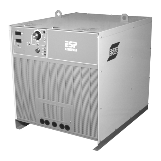
- Page 102 SECTION 7 Replacement Parts 7.3 Outside View – Front And Back ESP 600C Plasma Power Source...
- Page 103 SECTION 7 Replacement Parts Item No Part Number Description Circuit Symbol 35749 Base 35751 Panel Right Side 35753 Cover Top 951032 Lamp LED Red 12V PL4, PL5 2134926 Lamp Indicator Amber 951526 Lamp Neon White PL1, PL2 950122 Circuit Breaker 10A 950715 Potentiometer 15K 2W 2062170...
- Page 104 SECTION 7 Replacement Parts 7.4 Front View With PCBs Exposed View with LED meter panel removed (T-4) View with PCB Cover Removed ESP 600C Plasma Power Source...
- Page 105 SECTION 7 Replacement Parts Item No Part Number Description Circuit Symbol 38139 PCB Meter Digital PCB4 2062018 Potentiometer 10 K 2W 951502 Knob 950458 Switch Toggle DPDT 3 pos 38032 PC Board Control PCB1 635568 Terminal Block 18 pos 951275 Filter RFI 995103 Terminal Strip 24 pos...
- Page 106 SECTION 7 Replacement Parts 7.5 Right Side View ESP 600C Plasma Power Source...
- Page 107 SECTION 7 Replacement Parts Item No Part Number Description Circuit Symbol 35717 Transformer Control 674969 PCB Filter FN1,2 950704 RECT SIL Reverse 85A D29,30,35 950703 RECT SIL Forward 85A D31,32,34 973168 Terminal Strip 13 pos 17300008 Resistor 8 OHM 300W R12-17,24 17300001 Resistor 1 OHM 300W...
- Page 108 SECTION 7 Replacement Parts 7.6 Left Side View ESP 600C Plasma Power Source...
- Page 109 SECTION 7 Replacement Parts Item No Part Number Description Circuit Symbol C60,61,62, 35895 Kit Wire 600C 400V R55-57 951491 Contactor 3 pole 90A K2,K1a,1b,1c 2046333 Fuse Slo-Blo 15A 600V F1,2 672772 Capacitor 10 µf 370V C25,26,34-36 17280210 Resistor 1K ohms 100W R10,11,28-31 17280010 Resistor 10 ohms 100W...
- Page 110 SECTION 7 Replacement Parts 7.7 Top View 7-10 ESP 600C Plasma Power Source...
- Page 111 SECTION 7 Replacement Parts Item No Part Number Description Circuit Symbol 38030 PCB IGBT Driver PCB2,3 17750051 Resistor 10ohm 50W Noninductive R4-9 951828 Capacitor .033 µf 630V C13-18 951635 Capacitor 1900 µf 450V C1-12,29,32,33 951085 Switch Thermal 176 DEG F TS4-6 35779 Kit Wire ESP Control 460/575V...
- Page 112 SECTION 7 Replacement Parts 7.8 Back Inside View 7-12 ESP 600C Plasma Power Source...
- Page 113 SECTION 7 Replacement Parts Item No Part Number Description Circuit Symbol 2062334 Motor Fan 1/3 hP M1,2 17300001 Resistor 1 ohm 300W R1-3,21-23 17300004 Resistor 4 ohm 300W R18-20 ESP 600C Plasma Power Source 7-13...
- Page 114 SECTION 7 Replacement Parts 7.9 Middle Cross Section 7-14 ESP 600C Plasma Power Source...
- Page 115 SECTION 7 Replacement Parts Item No Part Number Description Circuit Symbol 951997 Transducer Current (ref) TD1,2 17280210 Resistor 1K ohms 100W R10,11 23610413 Resistor 2 ohms 25W R53,54 951816 Fan 230 V 50/60 Hz 677298 Fuse Assembly F8,9 ESP 600C Plasma Power Source 7-15...
- Page 116 SECTION 7 Replacement Parts 7.10 Front Cross Section –Behind Front Panel 7-16 ESP 600C Plasma Power Source...
- Page 117 SECTION 7 Replacement Parts Item No Part Number Description Circuit Symbol 17280210 Resistor 1k ohms 100W R10,11,28-31 2080196 Relay 3 pos brkt MT K3,5,6,7 Terminal Block 18 pos 0558004783 13730638 Diode Rectifier Reverse 800V 300A D7-12,25-28 13730639 Diode Rectifier Forward 800V 300A D13-18 950711 Switch Thermal 194 DegF...
- Page 118 SECTION 7 Replacement Parts This page intentionally left blank. 7-18 ESP 600C Plasma Power Source...
- Page 119 REVISION HISTORY Revision – Oct., 2004 – Added “1 - 14 AWG 600V lead to pilot arc connection in plumbing box (h.f. generator)” note to top diagram on page 3-7. Changed note 4 to read - “Connect the pilot arc cable to the pilot arc terminal in the primary power source.
- Page 120 Customer // Technical Support (843) 664-4405 (800) ESAB-123 (372-2123) ESAB Welding and Cutting Products PO BOX 100545 Ebenezer Road Florence, SC 29501-0545 http://www.esab.com ESAB Cutting Systems – Canada 6010 Tomken Road Mississauga, Ontario Canada L5T 1X9 Phone: (905) 670-0220 Fax: (905) 670-4879...
Need help?
Do you have a question about the ESP-600C and is the answer not in the manual?
Questions and answers