Table of Contents
Advertisement
INSTRUCTION MANUAL
SQUARE WAVE POWER SOURCES
These INSTRUCTIONS are for experienced operators. If you are not fully familiar with the principles of operation and
safe practices for arc welding equipment, we urge you to read our booklet, "Precautions and Safe Practices for Arc
Welding, Cutting, and Gouging", Form 52-529. Do NOT permit untrained persons to install, operate, or maintain this
equipment. Do NOT attempt to install or operate this equipment until you have read and fully understand these
instructions. If you do not fully understand these instructions, contact your supplier for further information. Be sure
to read the Safety Precautions (Section 1) before installing or operating this equipment.
Be sure this information reaches the operator.
You can get extra copies through your supplier.
Heliarc
P/N 31310 - Heliarc 250
P/N 31300 - Heliarc 250
NOTE: This manual is also suitable for use with L-TEC Heliarc 250 HF plus.
250
/
®
AC
DC
/
w/power factor
AC
DC
/
w/o power factor
AC
DC
F-15-047-A
February, 1995
Advertisement
Table of Contents

Related Manuals for ESAB Heliarc 250


Summary of Contents for ESAB Heliarc 250
- Page 1 P/N 31300 - Heliarc 250 w/o power factor NOTE: This manual is also suitable for use with L-TEC Heliarc 250 HF plus. These INSTRUCTIONS are for experienced operators. If you are not fully familiar with the principles of operation and safe practices for arc welding equipment, we urge you to read our booklet, "Precautions and Safe Practices for Arc...
-
Page 2: User Responsibility
USER RESPONSIBILITY This equipment will perform in conformity with the description thereof contained in this manual and accompanying labels and/or inserts when installed, operated, maintained and repaired in accordance with the instructions provided. This equipment must be checked periodically. Defective equipment should not be used. Parts that are broken, missing, worn, distorted or contaminated should be replaced immediately. -
Page 3: Safety Precautions
SAFETY PRECAUTIONS WARNING: hese Safety Precautions are for 5. Do not use equipment beyond its ratings. For example, your protection. They summarize precaution- overloaded welding cable can overheat and create a fire ary information from the references listed in hazard. Additional Safety Information section. - Page 4 2. Before performing any maintenance work inside a power FUMES AND GASES -- Fumes and gases, source, disconnect the power source from the incoming can cause discomfort or harm, particu- electrical power. larly in confined spaces. Do not breathe 3. Maintain cables, grounding wire, connections, power cord, fumes and gases.
- Page 5 The electronic firing circuit utilizes a voltage compensating circuit which compen- sates for line voltage variations of +/-10 percent. Through its unique design, the Heliarc 250 com- bines all of the latest state-of-the art magnetic and solid...
-
Page 6: Installation
SECTION 2 INSTALLATION 2.1 Installation Although designed with line voltage compensation, it is suggested the unit be operated on a separate circuit to assure that the performance of the machine is not im- Proper installation can contribute materially to the satis- paired due to an overloaded circuit. - Page 7 SECTION 2 INSTALLATION 2. For access to input terminal board, remove the 3. Thread the input conductor cables from the wall screws which secure the right side access panel of disconnect switch through the (strain relief) hole in the power source. The input terminal board, Figure the rear panel (see Fig.
- Page 8 SECTION 2 INSTALLATION The proper operation of the welding machine depends to a great extent on the use of output cables that are insulated copper, adequately sized, in good condition, and properly connected to the machine using UL listed pressure wire connectors. It is recommended that the Customer's Input Cable output cables be kept as short as possible (this is...
- Page 9 SECTION 2 INSTALLATION contactor operation at the welding station. Inter- top panel of the unit provides access for the meter connection to the power source is provided by its kit wiring to connect to the P16 receptacle provided 12-1/2-ft. cable/plug assembly. inside the power source.
-
Page 10: Operation
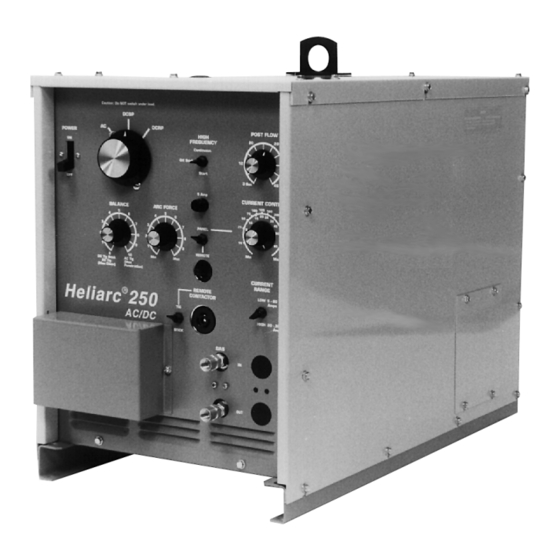
SECTION 3 OPERATION 3.1 Control Functions the switch in its DCSP mode causes the output terminals to assume the following polarities; work is positive, and torch/electrode is negative. Conversely, A. Power On-Off Switch (ROS). In the OFF position, when the switch is in DCRP; work is negative and the power source is electrically shut down;... - Page 11 SECTION 3 OPERATION L. Arc Force Potentiometer (AFP). This control is results from more reverse polarity which de- used in the STICK mode only. The lower settings creases the maximum current for a given elec- provide less short circuit current and a softer, more trode.
-
Page 12: Tig Welding
SECTION 3 OPERATION for welding of aluminum and magnesium. The DCSP position will normally be used to cover all of the remaining metals (steel, copper, refractory, Do not change the position of this switch while etc.) and alloys. The DCRP position produces a welding. - Page 13 SECTION 3 OPERATION Tungsten Electrodes main pot; however, if you want complete remote current control operation, the main potentiometer on the power source must be dial-set at 100 (or Welding Currents (Amps) maximum) on the dial. ACHF DCSP DCRP 10. Depending on your welding application, place the Electrode Using pure Using...
-
Page 14: Maintenance
SECTION 4 MAINTENANCE 4.1 Maintenance D. SPARK GAP ADJUSTMENT Generally, the high frequency output of the unit increases If this Equipment does not operate properly, stop work as the gap setting is increased. Electronic instability in immediately and investigate the cause of the malfunction. other equipment may occur if the gap is opened more Maintenance work must be performed by an experienced than the factory-set .025 inches (+/- 002-in.). - Page 15 SECTION 4 MAINTENANCE When replacing defective diodes, make sure mount- When replacing defective SCRs, make sure the ing surfaces are clean. Coat mounting surfaces mounting surfaces are clean. Coat the mounting with Dow-Corning No. 340 silicon heat sink com- surfaces with Alcoa No. 2 electrical joint com- pound, or equivalent.
-
Page 21: Replacement Parts
For technical assistance directly from an ESAB service representative, call (803) 664-4416 or 5550. Additionally, Always provide the series or serial number of the unit on ESAB offers toll free facsimile (FAX) service via 1-800- which the parts will be used. The serial number is 446-5693.
Need help?
Do you have a question about the Heliarc 250 and is the answer not in the manual?
Questions and answers