
Related Manuals for ESAB ET 220i AC/DC


Summary of Contents for ESAB ET 220i AC/DC
- Page 1 ESAB ET 220i AC/DC Operating Manual Art # A-12839_AB CURRENT 4010062 HF START PULSE Révision : AD Issue Date: October 26, 2016 Manual No.: 0-5346 esab.com...
- Page 2 WE APPRECIATE YOUR BUSINESS! Congratulations on your new ESAB product. We are proud to have you as our customer and will strive to provide you with the best service and reliability in the industry. This product is backed by our extensive warranty and world-wide service network. To locate your nearest distributor or service agency, visit us on the web at www.esab.com...
- Page 3 While the information contained in this Manual represents the Manufacturer's best judgement, the Manufac- turer assumes no liability for its use. Welding Power Supply Operating Manual Number 0-5346 for: ESAB ET 220i AC/DC Power Source Part Number W1009300 Published by: ESAB 2800 Airport Rd.
- Page 4 Be sure this information reaches the operator. You can get extra copies through your supplier. CAUTION These INSTRUCTIONS are for experienced operators. If you are not fully familiar with the principles of operation and safe practices for arc welding and cutting equipment, we urge you to read our booklet, “Precautions and Safe Practices for Arc Welding, Cut- ting, and Gouging,”...
-
Page 5: Table Of Contents
TABLE OF CONTENTS SECTION 1: SAFETY ..................1-1 Safety Precautions ..................1-1 SECTION 2: INTRODUCTION ..................2-1 2.01 How To Use This Manual ................2-1 2.02 Equipment Identification ................. 2-1 2.03 Receipt of Equipment ..................2-1 2.04 Description ..................... 2-1 2.05 User Responsibility .................. - Page 6 Routine Service and Calibration Requirements ..........5-4 5.04 Cleaning the Welding Power Source ............... 5-5 SECTION 6: KEY SPARE PARTS ................... 6-1 6.01 Key Spare Parts ....................6-2 APPENDIX A: CIRCUIT DIAGRAM OF ET 220i AC/DC ..........A-1 REVISION HISTORY ..................A-2...
-
Page 7: Section 1: Safety
SECTION 1: SAFETY Safety Precautions Users of ESAB welding and plasma cutting equipment have the ultimate responsibility for ensuring that anyone who works on or near the equipment observes all the relevant safety precautions. Safety precautions must meet the requirements that apply to this type of welding or plasma cutting equipment. The following recommendations should be observed in addition to the standard regulations that apply to the workplace. - Page 8 ET 220I AC/DC Arc welding and cutting can be injurious to yourself and others. Take WARNING precautions when welding and cutting. Ask for your employer's safety practices which should be based on manufacturers' hazard data. ELECTRIC SHOCK - Can kill.
-
Page 9: Introduction
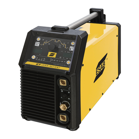
2.04 Description CAUTION The ET 220i AC/DC is light weight constant current welding A procedure which, if not properly followed, power sources incorporating the latest digital inverter technol- may cause damage to the equipment. -
Page 10: Transporting Methods
If using a fork lift vehicle, secure the Power Source on a proper skid before transporting. 2.07 Packaged Items ET 220i AC/DC Inverter Power Source (Part No. W1009300) • ET 220i AC/DC Inverter Power Source • Two male 50mm Dinse connectors •... -
Page 11: Specifications
ET 220I AC/DC 2.09 Specifications Description ET 220i AC/DC Power Source Part Number W1009300 Power Source Mass 29.5lbs (13.4Kg) without power cable Power Source Dimensions H13" x W7.25" x D19" (H326mm x W185mm x D483mm) Cooling Fan Cooled Welder Type... -
Page 12: Optional Accessories
Note 4: Generator Requirements at the Maximum Output Duty Cycle. Due to large variations in performance and specifications of different brands and types of generators, ESAB cannot guarantee full welding output power or duty cycle on every brand or type of generator. -
Page 13: Installation, Operation And Setup
ET 220I AC/DC SECTION 3: INSTALLATION, OPERATION AND SETUP 3.03 Ventilation 3.01 Environment These units are designed for use in environments with increased WARNING hazard of electric shock as outlined in IEC 60974-1. Since the inhalation of welding A. Examples of environments with increased hazard of electric... -
Page 14: High Frequency Introduction
ET 220I AC/DC NOTE! NOTE! This unit is equipped with a three-conduc- Note the available input power. Damage to tor with earth power cable that is con- the PCB could occur if 575VAC or higher is nected at the welding power source end for applied. -
Page 15: Electromagnetic Compatibility
ET 220I AC/DC 3.07 Electromagnetic Compatibility that are taking place. The surrounding area may extend beyond the boundaries of the premises. WARNING C. Methods of Reducing Electromagnetic Emissions Extra precautions for Electromagnetic 1. Mains Supply Compatibility may be required when this... -
Page 16: Power Source Controls, Indicators And Features
ET 220I AC/DC 3.08 Power Source Controls, Indicators and Features Art # A-12841 Figure 3-2: Controls on Front and Rear Panel 1. Electrode Welding Terminal Electrode Welding Terminal. Welding current flows from the Power Source via 50mm Dinse type terminals. It is essential, however, that the male plug is inserted and turned securely to achieve a sound electrical connection. - Page 17 Mains voltage potential. 6. Mains Supply Lead The ET 220i AC/DC is fitted with a heavy duty mains supply lead, 10ft long cable, no plug. 7. Gas Inlet The Shielding Gas Inlet connection is used to supply the appropriate shielding gas to the unit. The gas inlet is located on the rear of the Power Source.
- Page 18 ET 220I AC/DC Socket Pin Part Number / Description Trigger Switch Input Trigger Switch Input Remote Control 5k ohm Potentiometers Maximum Remote Control 5k ohm Potentiometers Wiper Remote Control 5k ohm Potentiometers Minimum Remote Control Enable (Short to common to enable remote control)
- Page 19 ET 220I AC/DC 13. Spot indicator light This light will illuminate when the power source is in GTAW SPOT welding mode. 14. Tiptronic indicator light (Refer to Section 3.12) This light will illuminate when the power source is in TIPTRONIC welding mode and a saved job has been loaded.
- Page 20 ET 220I AC/DC 25. Digital Ammeter / Parameter Codes The digital amperage meter is used to display both the pre-set current and actual output current of the power source. It is also used to display Welding Parameter Codes. Depending on the Welding Parameter selected, the status indictor adjacent to the ammeter will illuminate to show the units of the welding parameter.
- Page 21 ET 220I AC/DC Art # A-12843 Figure 3-6: Control Panel 38. Pre Flow indicator light This light will illuminate when the Pre Flow Welding Parameter is selected. 39. Initial Current time (GTAW) and Hot Start time (SMAW) indicator light This light will illuminate when the Initial Current Time Welding Parameter is selected in GTAW mode, or when Hot Start Time Welding Parameter is selected in SMAW mode.
-
Page 22: Setup For Tig (Gtaw) Welding
ET 220I AC/DC 48. Crater Current time indicator light This light will illuminate when the Crater Current Time Welding Parameter is selected. 49. Electrode Diameter Out-of-Range indicator light This light will illuminate when the set welding current is outside the normal operating range for the selected Electrode Diameter. - Page 23 ET 220I AC/DC Art # A-12844 Figure 3-7: Setup for TIG Welding Manual 0-5346 INSTALLATION, OPERATION AND SETUP 3-11...
- Page 24 ET 220I AC/DC • First, select a Welding Type by pressing the Weld Type (17) button. Welding Type Welding Type Selection DC HF TIG AC Liftarc TIG DC Liftarc TIG AC HF TIG • Then, select a Welding Mode by pressing the WELDING MODE (10) button.
-
Page 25: Tig (Gtaw) Programming Mode
ET 220I AC/DC 3.10 TIG (GTAW) Programming Mode Art # A-12845 Figure 3-8: TIG Programming Mode • Press the WELDING MODE (10) button to select the appropriate GTAW mode. Several GTAW operating modes are available. 2T (normal mode). The 2T LED (16) will illuminate. - Page 26 GTAW mode is it has been depressed. In 2T mode limited to 220A for the Initial Current remains on for the the ET 220i AC/DC. Start Current Time tS and then the Up Slope current ramp will commence. Start Current Time tS...
- Page 27 Trough. in GTAW mode is limited to 220A for the ET 220i AC/DC. Down Slope Time This parameter operates in GTAW 0 – 99% modes only and is used to set the time for the weld current to ramp down to the crater current.
- Page 28 ET 220I AC/DC Parameter Range LED Code Parameter Value Factory (Left Display) (Right Display) Setting AC balance (AC Output Mode only) This parameter operates in AC 10 – 90% positive GTAW modes and is used to set the welding current penetration to cleaning action ratio for the AC weld current.
- Page 29 ET 220I AC/DC AC BALANCE is used for aluminium welding in AC HF GTAW or AC LIFT GTAW operating modes. It is used to set the ratio of penetration to cleaning action for the AC GTAW welding arc. Maximum weld penetration is achieved when the AC BALANCE is set to 10%. Maximum cleaning of heavily oxidized aluminium or magnesium alloys is achieved when the WAVE BALANCE is set to 90%.
-
Page 30: Tig (Gtaw) Welding Secondary Parameters
ET 220I AC/DC 3.11 TIG (GTAW) Welding Secondary Parameters Secondary parameters are available. These are required to be set separately. • Press and hold the WELDING MODE (10) button then press the SAVE (54) button. • Press the BACK button (22) or FORWARD button (23) to select the Parameter. -
Page 31: Gtaw Spot Welding Mode With Dwell Time (Stitch Mode)
ET 220I AC/DC 3.12 GTAW Spot Welding Mode with DWELL Time (Stitch Mode) Art # A-12846 Figure 3-9: GTAW Spot Welding Mode with DWELL Time To enable Spot Welding with Dwell Time (Stitch welding) the parameter “PSP” needs to be set to ON (refer secondary parameters) it is possible to have automated spot welds with this Stitch function. -
Page 32: Tip Tronic Operation
ET 220I AC/DC 3.13 Tip Tronic Operation In GTAW modes, up to 100 jobs can be saved. These are arranged as 10 jobs numbers, in 10 job sets. These are shown on the meter displays. The first number on the display is the job set, the second is the job number. In the example, the job set is 2 and the job number is 9. - Page 33 ET 220I AC/DC Load a TipTronic Job • Using the Welding Mode button (10) select TipTronic mode (14). Either 2T or the 4T may be lighted as well as the TT symbol for Tip Tronic setting depending on the last saved job.
-
Page 34: Setup For Stick (Smaw) Welding
ET 220I AC/DC 3.14 Setup for Stick (SMAW) Welding A. Connect the Electrode Holder lead to the Electrode welding terminal (top). If in doubt, consult the electrode manufacturer. Welding current flows from the Power Source via 50mm Dinse type terminals. It is essential, however, that the male plug is inserted and turned securely to achieve a sound electrical connection. -
Page 35: Stick (Smaw) Programming Mode
ET 220I AC/DC • First, select Stick Mode by pressing the Welding Mode (10) button. Welding Type Welding Mode Selection Stick Mode • Then, select Welding Type by pressing the welding Type (17) button. Welding Type Welding Type Selection DC Negative Stick DC Positive Stick 3.15 Stick (SMAW) Programming Mode... - Page 36 SMAW mode is current. limited to 170A for e.g. HOT START current = 125 the ET 220i AC/DC. amps when welding current = 100 amps & HOT START = 125% Hot Start Time tS...
- Page 37 ET 220I AC/DC Art # A-12850 Figure 3-13: Stick Programming Mode Press and hold the WELDING MODE (10) button then press the SAVE (53) button. The Arc Dynamic Parameter is selected. In the left hand AMPS display dAr is displayed. In the right hand VOLTS display, the value of the parameter is displayed.
-
Page 38: User Specific Menus
ET 220I AC/DC 3.16 User Specific Menus Art # A-12851 Figure 3-14: User Specific Menus • Switch off the power to the unit. Press and hold the BACK Welding Parameter Button (22) . Switch on the power to the unit. -
Page 39: Special Function
ET 220I AC/DC Menu item Range LED Code Parameter Value Factory (Left Display) (Right Display) Setting C08 – Foot Control Minimum Current (GTAW AC mode only) When set to “ON” the increased Foot Control Minimum current is disabled and the minimum current on any electrode is 5A. - Page 40 ET 220I AC/DC Master Reset WARNING All saved TipTronic jobs will be erased. All welding and secondary parameters will be restored to the factory setting. • Press and hold the BACK button (22). • Press the hold the SAVE button (53).
- Page 41 ET 220I AC/DC Fan Test • Press and hold the BACK button (22). • Press the WELDING TYPE button (17). • The fan will run for approximately 30 seconds. • If the BACK button (22) and WELDING TYPE button (17) are pressed again while the fan is running, the fan test is halted.
-
Page 42: Shielding Gas Regulator/ Flowmeter Operating Instructions
ET 220I AC/DC 3.18 Shielding Gas Regulator/ Flowmeter Operating Instructions WARNING This equipment is designed for use with welding grade (Inert) shielding gases only. Shielding Gas Regulator/ Flowmeter Safety This regulator/ flowmeter is designed to reduce and control high pressure gas from a cylinder or pipeline to the working pressure required for the equipment using it. - Page 43 ET 220I AC/DC NOTE! All valves downstream of the regulator/ flowmeter must be opened to obtain a true flow rate reading on the outlet gauge. (Welding power source must be triggered) Close the valves after the pressure has been set.
-
Page 44: Foot Control, Part No. W4013200 (Optional Accessory)
ET 220I AC/DC Shutdown Close cylinder valve whenever the regulator/ flowmeter is not in use. To shut down for extended periods (more than 30 minutes). 1. Close cylinder or upstream valve tightly. 2. Open downstream equipment valves to drain the lines. Bleed gas into a well ventilated area and away from any ignition source. - Page 45 ET 220I AC/DC Description The Tweco Foot Control is a foot operated switch and potentiometer which starts and stops the welding process and controls welding current through operation of the foot pedal. Refer to list below for compatible Tweco power sources.
- Page 46 ET 220I AC/DC This Page Intentionally Blank INSTALLATION, OPERATION AND SETUP Manual 0-5346 3-34...
-
Page 47: Basic Welding Guide
ET 220I AC/DC SECTION 4: BASIC WELDING GUIDE 4.01 Stick (SMAW) Basic Welding Technique Size of Electrode The electrode size is determined by the thickness of metals being joined and can also be governed by the type of welding machine available. - Page 48 ET 220I AC/DC Art # A-07688 Figure 4-2: Flat Position, Gravity Fillet Weld Art # A-07689 Figure 4-3: Horizontal Position, Butt Weld Art # A-07690 Figure 4-4: Horizontal-Vertical (HV) Position Art A-07691 Figure 4-5: Vertical Position, Butt Weld Art # A-07692...
- Page 49 ET 220I AC/DC Art # A-07694 Figure 4-8: Overhead Position, Fillet Weld Joint Preparations In many cases, it will be possible to weld steel sections without any special preparation. For heavier sections and for repair work on castings, etc., it will be necessary to cut or grind an angle between the pieces being joined to ensure proper penetration of the weld metal and to produce sound joints.
- Page 50 ET 220I AC/DC Arc Welding Technique - A Word to Beginners blobs. The weld bead is flattened and spatter increases. A short arc is essential if a high quality weld is to be obtained although For those who have not yet done any welding, the simplest way if it is too short there is the danger of it being blanketed by slag to commence is to run beads on a piece of scrap plate.
- Page 51 ET 220I AC/DC Art # A-07700_AB Art # A-07698 Figure 4-12: Weld Build up Sequence Heavy plate will require several runs to complete the joint. Figure 4-14: Multi-runs in HV Fillet Weld After completing the first run, chip the slag out and clean the weld with a wire brush.
- Page 52 ET 220I AC/DC Art # A-07702 Art # A-07704 Figure 4-18: Overhead Fillet Weld Figure 4-16: Multi Run Vertical Fillet Weld Distortion Distortion in some degree is present in all forms of welding. In many cases it is so small that it is barely perceptible, but in other cases allowance has to be made before welding commences for the distortion that will subsequently occur.
- Page 53 ET 220I AC/DC stresses (distortion), or the weld may crack, in any case, there will remain "locked-up" stresses in the job. Figures 4-19 and 4- 20 illustrate how distortion is created. Upsetting Weld Art # A-07705_AB Art # A-07707 Expansion with...
-
Page 54: Stick (Smaw) Welding Troubleshooting
ET 220I AC/DC Art # A-07428_AB Figure 4-26: Chain Intermittent Welding Art # A-07713_AB Figure 4-27: Staggered Intermittent Welding 4.02 Stick (SMAW) Welding Troubleshooting FAULT CAUSE REMEDY 1 Welding current varying ARC FORCE parameter is Reduce the ARC FORCE parameter until welding... - Page 55 ET 220I AC/DC Art: A-04971 Figure 1: Example of insufficient gap or incorrect sequence 4 A groove has been formed A Welding current is too A Reduce welding current. in the base metal adjacent high. to the toe of a weld and has B Welding arc is too long.
- Page 56 ET 220I AC/DC 6 Gas pockets or voids in A High levels of sulphur in A Use an electrode that is designed for high weld metal (porosity) steel. sulphur steels. B Electrodes are damp. B Dry electrodes before use. C Welding current is too C Reduce welding current.
-
Page 57: Tig (Gtaw) Basic Welding Technique
ET 220I AC/DC 4.03 TIG (GTAW) Basic Welding Technique Gas Tungsten Arc Welding (GTAW) or TIG (Tungsten Inert Gas) as it is commonly referred to, is a welding process in which fusion is produced by an electric arc that is established between a single tungsten (non-consumable) electrode and the work piece. Shielding is obtained from a welding grade shielding gas or welding grade shielding gas mixture which is generally Argon based. - Page 58 ET 220I AC/DC Tungsten Electrode Types Electrode Type Welding Application Features Colour Code (Ground Finish) DC welding of mild steel, stainless steel Excellent arc starting, Long life, High Thoriated 2% and copper current carrying capacity Self cleaning, Long life, Maintains...
-
Page 59: Tig (Gtaw) Welding Problems
Arc Welding section are applicable a comprehensive outline of the TIG Welding process is outside the scope of this Operating Manual. For further information please refer to www.esab.com or contact ESAB. 4.04 TIG (GTAW) Welding Problems... - Page 60 Electrode Selection Chart. B The wrong electrode B Select the right tungsten electrode is being used for the type. Refer to Table 4-5 ESAB Tungsten welding job. Electrode Selection Chart. C Gas flow rate is too C Select the right rate for the welding job.
-
Page 61: Power Source Problems And Routine Service Requirements
If major complex subassemblies are faulty, then the Welding Power Source must be returned to an accredited ESAB Service Provider for repair. The basic level of troubleshooting is that which can be performed without special equipment or knowledge. Refer also to section 4 for solving welding problems. - Page 62 ET 220I AC/DC Error Messages If a message has been displayed, have an Accredited ESAB Service Provider check the power source. Message Code Error Cause Possible Remedy Thermal Overload of Duty Cycle has been Leave the power source switched ON...
-
Page 63: Power Source Problems
Replace primary control fuse. ON. Indicator light is not lit Broken connection in primary and welding arc cannot be circuit. Have an Accredited ESAB Service Provider established. check primary circuit. 3 Error Code E01 is displayed Duty cycle of power source has... -
Page 64: Routine Service And Calibration Requirements
2. The Earth Ground terminal of the associated plug of a transportable power source Note that due to the dangers of stray output currents damaging fixed wiring, the integrity of fixed wiring supplying ESAB welding power sources should be inspected by a licensed electrical worker in accordance with the requirements below - 1. -
Page 65: Cleaning The Welding Power Source
All unsafe accessories shall not be used. Repairs If any parts are damaged for any reason, it is recommended that replacement be performed by an accredited ESAB Service Provider. Power Source Calibration A. - Page 66 ET 220I AC/DC This Page Intentionally Blank POWER SOURCE PROBLEMS AND ROUTINE SERVICE REQUIREMENTS Manual 0-5346...
- Page 67 ET 201I AC/DC SECTION 6: KEY SPARE PARTS This Page Intentionally Blank. See next two pages. 0-5346 KEY SPARE PARTS...
-
Page 68: Key Spare Parts
ET 201I AC/DC 6.01 Key Spare Parts A-12885_AB Figure 6-1: Spare Parts KEY SPARE PARTS 0-5346... -
Page 69: Key Spare Parts
ET 201I AC/DC ET 220i AC/DC Spare Parts Item Part Number Description W7006300 Clear Control Panel Cover W7006301 Gas Outlet, Front Panel W7006301 Gas Inlet, Rear Panel W7006500 Knob, Control W7006323 PCB Secondary Rectifier W7006433 PCB Control W7006434 PCB Primary Inverter... - Page 70 ET 201I AC/DC This Page Intentionally Blank KEY SPARE PARTS 0-5346...
-
Page 71: Appendix A: Circuit Diagram Of Et 220I Ac/Dc
ET 220I AC/DC APPENDIX A: CIRCUIT DIAGRAM OF ET 220i AC/DC X1/1 +VCC X1/2 X1/3 CAN_L CAN_H X1/4 X1/5 X18/1 X1/6 X18/2 X1/7 X18/3 X11/1 X1/8 X18/4 REL02 X4/1 X10/1 X4/2 X10/2 X11/2 X4/3 X10/3 X13/1 X13/2 X3/1 X15/1 braun... -
Page 72: Revision History
ET 220I AC/DC REVISION HISTORY Cover Date Rev. Change(s) 05/07/15 Manual release 01/15/16 Updated 'Liftarc TIG' wording, Section 6 art, spart parts list and Appendix art. APPENDIX Manual 0-5346... - Page 74 SOUTH AFRICA Bucharest Vamberk Tel: +40 316 900 600 ESAB Mexico S.A. ESAB Africa Welding & Cutting Ltd Tel: +420 2 819 40 885 Fax: +40 316 900 601 Monterrey Durbanvill 7570 - Cape Town Fax: +420 2 819 40 120...
Need help?
Do you have a question about the ET 220i AC/DC and is the answer not in the manual?
Questions and answers