Hakko Electronics 485 Instruction Manual
Hide thumbs
Also See for 485:
- Instruction manual (10 pages) ,
- Instruction manual (8 pages) ,
- Care and feeding (2 pages)
Advertisement
Quick Links
Instruction Manual
Thank you for purchasing the HAKKO 485 soldering system.
Please read this manual before operating the HAKKO 485.
Keep this manual readily accesible for reference.
We supply Hakko 485 soldering system
without solder for using lead-free users.
Although a little lead-free solder (Sn 97%, Ag 3%)
still remains in the solder bath due to inspection before shipment.
It will not effect the use or efficiency of this product.
●
●
Advertisement

Subscribe to Our Youtube Channel
Related Manuals for Hakko Electronics 485


Summary of Contents for Hakko Electronics 485
- Page 1 Instruction Manual ● Thank you for purchasing the HAKKO 485 soldering system. Please read this manual before operating the HAKKO 485. Keep this manual readily accesible for reference. ● We supply Hakko 485 soldering system without solder for using lead-free users.
-
Page 2: Packing List
1. PACKING LIST HAKKO 486 (Air unit) HAKKO 485 Anti-oxidizer (No.486-026) Air hood for 42P (No.485-31) Air hood for 28P (No.485-30) Air hood for 18/20P (No.485-29) Air hood for 14/16P (No.485-28) Nozzle for 42P (485-N-04) Nozzle for 28P (485-N-03) Nozzle for 18/20P (485-N-02) Nozzle for 14/16P (485-N-01) Lamp (No.485-10) -
Page 3: Specifications
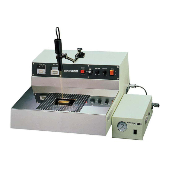
7. SETTING UP Sample of adjustment Temperature control meter (No.485-49) HAKKO 485 and 486 Air unit Digital solder flow duration meter (No.485-50) Locator light (No.485-26) A. Through-hole P.W.B on both side HAKKO 485 HAKKO 486 (Air unit) Locator light switch (”READY” lamp) (NO.485-59) - Page 4 2. THE INTERNAL PARTS OF THE BODY Motor Motor control unit Transformer S.S.R. Current leakage breaker Timer RX relay Timer FX relay AX relay Timer "READY" Power lamp & Sensor Switch Volume Volume locator activated light switch switch Flow Slow level level 120V...
- Page 5 2) Turn the power switch ON and wait 30 -40 Hex screw minutes for the solder in the bath to melt. (2.0 mm) Joint 3) Using a 2.0mm hex wrench, remove the 2 screws securing the joint to the impeller Impeller and let the impeller drop down.
- Page 6 ● Use only genuine HAKKO replacement parts. concerning use of the appliance by a person responsible for their safety. ● Do not allow the HAKKO 485 to become wet, or use it with wet hands. ● Children should be supervised to ensure that they do not play ● Be sure the work area is well ventilated.
- Page 7 7. The valve has gone bad. Plug the HAKKO 486(Air unit) into Plug the air ose into the side Adjust the feet on the HAKKO 485 3p metal connector of the HAKKO (Fig.2) of the HAKKO 486(Air unit). so that it is stable and level.
-
Page 8: Operation
4. OPERATION CAUTION For safety reasons, be sure to ground the unit by connecting the ground wire to a grounded terminal. First, plug the power cord into a grounded wall socket, then open the rear panel of the unit and turn on the Circuit Breaker. - Page 9 Mode - MANUAL Mode - MANUAL Turn the key switch to MANUAL mode. Turn the key switch to MANUAL mode. Depress the foot switch and adjust the solder flow as Depress the foot switch and adjust the solder flow as desired using the solder flow dial.
-
Page 10: Troubleshooting Guide
5. TROUBLE SHOOTING GUIDE ●If the”POWER” lamp should fail to light, yet the solder bath has reached the desired temperature, check whether the bulb needs to be replaced. 2PELB Power switch 3P Plug ●Should the solder bath not heat to the desired temperature, although the ▼ (red) lamp lights, 120 V 100 V the cause is likely one or more of the following:... - Page 11 7. The valve has gone bad. Plug the HAKKO 486(Air unit) into Plug the air ose into the side Adjust the feet on the HAKKO 485 3p metal connector of the HAKKO (Fig.2) of the HAKKO 486(Air unit). so that it is stable and level.
- Page 12 6. CLEANING THE SOLDER BATH A. Daily cleaning Clean before or after every use. ● Remove the table. ● Remove any and all oxide inside the bath using the provided spatula. ● Replace the anti-oxidizer on the anti-oxidizer plate. Anti-oxidizer palte Joint Bolt Impeller...
- Page 13 2) Turn the power switch ON and wait 30 -40 Hex screw minutes for the solder in the bath to melt. (2.0 mm) Joint 3) Using a 2.0mm hex wrench, remove the 2 screws securing the joint to the impeller Impeller and let the impeller drop down.
- Page 14 7) Place the Impeller into the Chamber and secure the Chamber to the bottom plate. Place the Chamber into the bath over the 2 bolts. 8) Insert the Anti-oxidizer plate over the Impeller and the nearest bath bolt. Anti-oxidizer plate Chamber Impeller Bolt...
- Page 15 7. SETTING UP Sample of adjustment Temperature control meter (No.485-49) HAKKO 485 and 486 Air unit Digital solder flow duration meter (No.485-50) Locator light (No.485-26) A. Through-hole P.W.B on both side HAKKO 485 HAKKO 486 (Air unit) Locator light switch (”READY” lamp) (NO.485-59)
- Page 16 8. USING THE TEMPERATURE CONTROL METER Set the temperature according to Temperature Output mode the following procedures. display indicator Deviation (Factory setting is 250℃) indicator Press the selector key located on the front. Confirm that the unit is in “Set Temperature” mode. Mode indicator (the mode indicator is illuminated).
Need help?
Do you have a question about the 485 and is the answer not in the manual?
Questions and answers