Hakko Electronics 485 Instruction Manual
Hide thumbs
Also See for 485:
- Instruction manual (10 pages) ,
- Instruction manual (16 pages) ,
- Care and feeding (2 pages)
Table of Contents
Advertisement
Quick Links
Download this manual
See also:
Instruction Manual
8. USING THE TEMPERATURE CONTROL METER
Temperature
Output mode
display
indicator
Deviation
indicator
Mode
indicator
Current temperature/
Setting key
Setting key
Set temperature/
(Down)
(Up)
Mode selector key
HEAD OFFICE
4-5, Shiokusa 2-chome, Naniwa-ku, Osaka 556-0024 JAPAN
TEL:+81-6-6561-3225 FAX:+81-6-6561-8466
http://www.hakko.com E-mail:sales@hakko.com
OVERSEAS AFFILIATES
U.S.A.: AMERICAN HAKKO PRODUCTS, INC.
TEL: (661) 294-0090 FAX: (661) 294-0096
Toll Free (800)88-HAKKO
4 2 5 5 6
http://www.hakkousa.com
HONG KONG: HAKKO DEVELOPMENT CO., LTD.
TEL: 2811-5588 FAX: 2590-0217
http://www.hakko.com.hk
E-mail:info@hakko.com.hk
SINGAPORE: HAKKO PRODUCTS PTE., LTD.
TEL: 6748-2277 FAX: 6744-0033
http://www.hakko.com.sg
E-mail:sales@hakko.com.sg
Please access to the following address for the other Sales affiliates.
http://www.hakko.com
© 2000-2016 HAKKO Corporation. All Rights Reserved.
Set the temperature according to
the following procedures.
(Factory setting is 250℃)
Press the selector key
located on
the front. Confirm that the unit is in
"Set Temperature" mode.
(the mode indicator is illuminated).
↓
Set the temperature using
the UP and DOWN keys.
MA02559XZ160729
Thank you for purchasing the HAKKO 485 soldering system.
Please read this manual before operating the HAKKO 485.
still remains in the solder bath due to inspection before shipment.
It will not effect the use or efficiency of this product.
2016.7
Instruction Manual
●
Keep this manual readily accesible for reference.
●
We supply Hakko 485 soldering system
without solder for using lead-free users.
Although a little lead-free solder (Sn 97%, Ag 3%)
Advertisement
Table of Contents

Subscribe to Our Youtube Channel
Related Manuals for Hakko Electronics 485


Summary of Contents for Hakko Electronics 485
- Page 1 (Up) Mode selector key the UP and DOWN keys. ● Thank you for purchasing the HAKKO 485 soldering system. Please read this manual before operating the HAKKO 485. Keep this manual readily accesible for reference. ● We supply Hakko 485 soldering system without solder for using lead-free users.
-
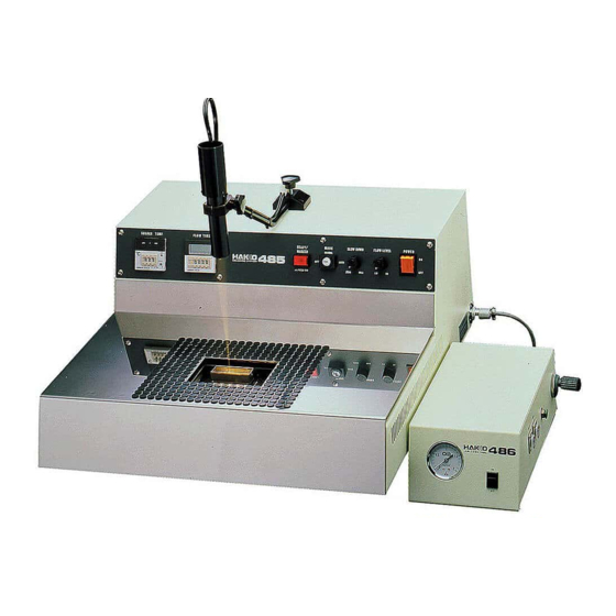
Page 2: Packing List
1. PACKING LIST 7. SETTING UP Sample of adjustment HAKKO 485 and 486 Air unit HAKKO 486 (Air unit) A. Through-hole P.W.B on both side HAKKO 485 HAKKO 485 HAKKO 486 (Air unit) Temperature Nozzle Flow Time Delay Time Control Pressure 250℃... - Page 3 7) Place the Impeller into the Chamber and secure the Chamber to the bottom plate. Temperature control meter (No.485-49) Place the Chamber into the bath over the 2 bolts. Digital solder flow duration meter (No.485-50) 8) Insert the Anti-oxidizer plate over the Impeller and the nearest bath bolt. Locator light (No.485-26) Anti-oxidizer plate Locator light switch (”READY”...
- Page 4 2. THE INTERNAL PARTS OF THE BODY Motor Motor control unit 2) Turn the power switch ON and wait 30 -40 Hex screw Transformer minutes for the solder in the bath to melt. (2.0 mm) Joint 3) Using a 2.0mm hex wrench, remove the 2 screws securing the joint to the impeller Impeller and let the impeller drop down.
- Page 5 6. CLEANING THE SOLDER BATH A. Daily cleaning Clean before or after every use. ● Remove the table. ● Remove any and all oxide inside the bath using the provided spatula. ● Replace the anti-oxidizer on the anti-oxidizer plate. Anti-oxidizer palte Joint Bolt Impeller...
-
Page 6: Replacing The Sensor
● Use only genuine HAKKO replacement parts. concerning use of the appliance by a person responsible for their safety. ● Do not allow the HAKKO 485 to become wet, or use it with wet hands. 7. The valve has gone bad. -
Page 7: Troubleshooting Guide
Replacing the heater Plug the HAKKO 486(Air unit) into Plug the air ose into the side Adjust the feet on the HAKKO 485 3p metal connector of the HAKKO (Fig.2) of the HAKKO 486(Air unit). so that it is stable and level. -
Page 8: Operation
4. OPERATION CAUTION Mode - MANUAL For safety reasons, be sure to ground the unit Turn the key switch to MANUAL mode. by connecting the ground wire to a grounded terminal. Depress the foot switch and adjust the solder flow as desired using the solder flow dial.
Need help?
Do you have a question about the 485 and is the answer not in the manual?
Questions and answers