Honeywell CT40 Series Instructions Manual
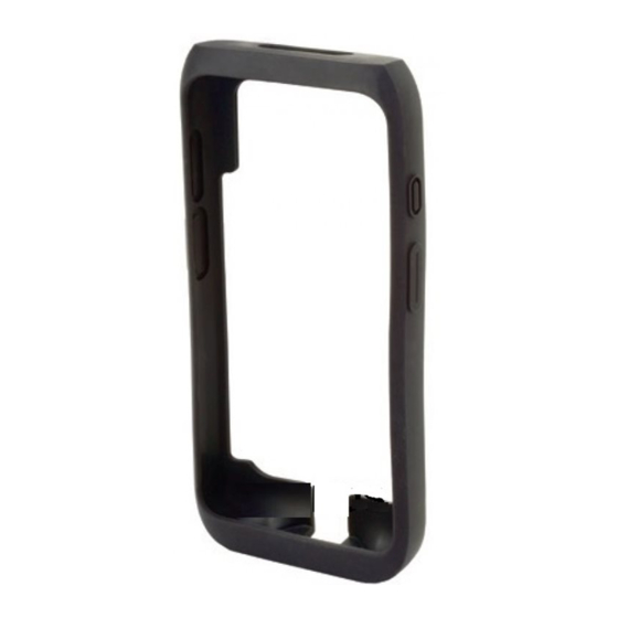
Protective boot and accessories
Hide thumbs
Also See for CT40 Series:
- User manual (120 pages) ,
- Quick start manual (25 pages) ,
- Quick start manual (15 pages)

Related Manuals for Honeywell CT40 Series


Summary of Contents for Honeywell CT40 Series
- Page 1 CT40 Protective Boot and Accessories Models CT40-PB-00, CT40-SH-PB, CT40-CB-PB, CT40-NB-PB Instructions CT40-HBT-EN-IN-01 Rev A 7/19...
- Page 2 Out of Box The CT40 protective boot is available as a stand-alone accessory (model CT40-PB-00) or part of a kit that includes the scan handle (model CT40-SH-PB). "Charge Base and Ethernet Base" for compatible communication and charging bases. Attach the Protective Boot When used with the scan handle, the hand strap should be removed prior to installation.
- Page 3 Press down evenly.
- Page 4 Verify the boot lip overlaps the front of the CT40...
- Page 5 Attach Scan Handle Insert the handle tab into the unit/boot assembly. Press and hold the latch. Lower the handle down and release the latch. Note: Remove hand strap before assembly.
- Page 6 Scan a Bar Code Press the trigger on the handle to scan a bar code.
- Page 7 Remove Scan Handle Press and hold the button.
- Page 8 Lift handle end and release button. Slide handle tab out of unit/boot assembly.
- Page 9 Remove Protective Boot Note: The protective boot does not need to be removed for battery replacement or charging with a compatible base (see "Charge Base and Ethernet Base"). Routinely inspect the protective boot for damage, and replace with part number CT40-PB-00 if needed. Hold the unit, with the screen facing you, on both sides.
- Page 10 Lift the unit up and out of the bottom of the boot.
- Page 11 Charge Base or Net Base for service or if you want to store the charger while not in use. Caution: We recommend the use of Honeywell accessories and power adapters. Use of any non- Honeywell accessories or power adapters may cause damage not covered by the warranty.
- Page 12 Connect Base to Power Use only a UL Listed power supply which has been qualified by Honeywell with an output rated at 12V/7A. The power supply input rating is 100-240 VAC, 50/60 Hz. The operating temperature is -10 °C to 50 °C (14 °F to 122 °F).
- Page 13 Charge the Battery Pack Caution: Make sure that all components are dry prior to using the computers and batteries with accessories. Using wet components may cause damage not covered by the warranty. Mise en garde : Assurez-vous que tous les composants sont secs avant de connecter les terminaux/batteries à...
- Page 14 Mount the Charge Base or Net Base You can mount the charger on a flat, horizontal surface such as a desktop or workbench with an optional DIN rail. Mounting hardware required: • DIN rail • 3/16-inch diameter x 5/8-inch long pan head screw •...
-
Page 15: Limited Warranty
Patents For patent information, see www.hsmpats.com. Disclaimer Honeywell International Inc. (“HII”) reserves the right to make changes in specifications and other information contained in this document without prior notice, and the reader should in all cases consult HII to determine whether any such changes have been made. - Page 16 This document contains proprietary information that is protected by copyright. All rights are reserved. No part of this document may be photocopied, reproduced, or translated into another language without the prior written consent of HII. Copyright2019 Honeywell International Inc. All rights reserved.
Need help?
Do you have a question about the CT40 Series and is the answer not in the manual?
Questions and answers