Advertisement
Quick Links
1118 WIRELESS REMOTE
INDICATOR LIGHT
Installation Guide
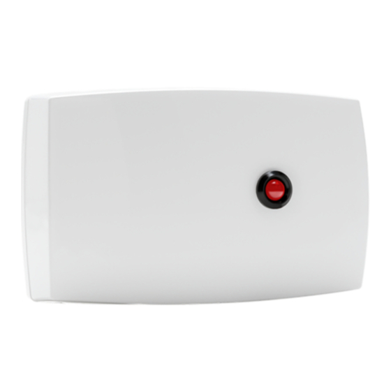
Figure 1: 1118 Wireless Remote
Indicator Light
DESCRIPTION
The 1118 Wireless Remote Indicator Light
provides one remote LED indicator that
can be used to visually notify the user
that a panic alarm has been activated.
The 1118 is designed to operate with
one CR123A battery or optional
12 VDC power supply.
Compatibility
•
XR150/XR550 Series panels
•
1100X Series wireless receivers with
Version 104 or higher.
What is Included?
•
1118 Wireless Remote Indicator Light
•
3 V Lithium CR123A battery
•
Hardware pack
1
PROGRAM THE PANEL
Program the 1118 as a panic alarm output. Refer to the
panel programming guide as needed.
1.
In OUTPUT INFO, enter the OUTPUT number.
2. Enter the OUTPUT NAME.
3. Enter the eight-digit SERIAL# and press CMD.
4. Enter the SUPRVSN TIME and press CMD.
5. Press the back arrow when OUTPUT INFO
displays.
6. Press the back arrow to OUTPUT OPTIONS and
select CMD.
7.
Navigate to PANIC ALM OUT and select a top
row key or area.
8. Enter the output number for the 1118. Select
CMD.
9. Press CMD until STOP displays and then press
any select area to save and exit programming.
Program Slow Response
Use wireless output numbers 450-474 to indicate
whether the wireless device responds within 15
seconds to trip the output (slow response).
Program Fast Response
Use wireless output numbers 480-499 to indicate
whether the wireless device responds within 1 second
to trip the output (fast response).
Note: For wireless output troubles to display
at a keypad, specify the keypad address at the
AUX 1 ZONES option in the Status List menu.
2
POWER THE 1118
Power the device with a 3 V lithium battery or a
12 VDC power supply, such as a DMP Model 376L
or DMP Model 505-12. Do not install a battery if the
device is being powered by a power supply. The
power supply does not charge the battery.
CR123A 3.0 V Lithium Battery
The device can be powered with a 3.0 V lithium
battery.
1.
Remove the housing cover.
2. Install the supplied jumper on the two pins next
to BAT on the power source header.
3. Place the battery in the holder and observe
polarity.
4. Snap the cover back into place.
Advertisement

Subscribe to Our Youtube Channel
Related Manuals for DMP Electronics 1118


Summary of Contents for DMP Electronics 1118
- Page 1 1118 WIRELESS REMOTE INDICATOR LIGHT Installation Guide PROGRAM THE PANEL Program the 1118 as a panic alarm output. Refer to the panel programming guide as needed. In OUTPUT INFO, enter the OUTPUT number. 2. Enter the OUTPUT NAME. 3. Enter the eight-digit SERIAL# and press CMD.
- Page 2 LED blinks immediately on and immediately off. Faulty: If communication is faulty, the LED remains on for about 8 seconds or flashes multiple times in quick succession. Relocate the device or receiver until the LED confirms clear communication. 1118 INSTALLATION GUIDE DIGITAL MONITORING PRODUCTS...
- Page 3 MOUNT THE 1118 Mount the device on a flat surface such as a wall or single-gang box. If using the optional Model 376L plug-in power supply, mount the device near a wall outlet. See Figure 4 for mounting hole locations on the housing base.
- Page 4 établies par le Code de sécurité 6 de Santé Canada. Le système doit être installé à une distance minimale de 7.87 pouces (20 cm) séparant l’antenne d’une personne présente en conformité avec les limites permises d’exposition du grand public. 1118 WIRELESS Accessories CR123 DMP 3 V Lithium Battery...
Need help?
Do you have a question about the 1118 and is the answer not in the manual?
Questions and answers