Table of Contents
Advertisement
Quick Links
Advertisement
Table of Contents

Related Manuals for Trotec TAC V+


Summary of Contents for Trotec TAC V+
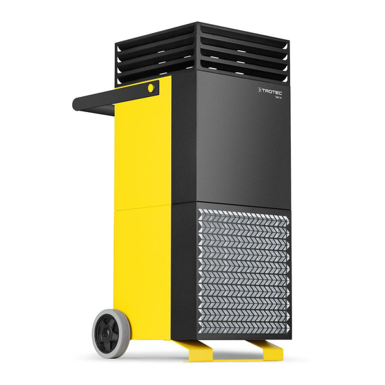
- Page 1 TAC V+ ORIGINAL INSTRUCTIONS HIGH-PERFORMANCE AIR PURIFIER...
-
Page 2: Table Of Contents
Technical annex.............. 15 Disposal ................ 25 TAC V+ Declaration of conformity ........... 25 Notes regarding the instructions https://hub.trotec.com/?id=44570 Symbols Safety Warning of electrical voltage Read this manual carefully before starting or using the This symbol indicates dangers to the life and health of device. - Page 3 • Do not under any circumstances use the device if you Warning detect damages on the mains plug or power cable. Children of less than 3 years should be kept away from If the supply cord is damaged, it must be replaced by the the device unless continuously supervised.
- Page 4 Improper use Residual risks • Do not place the device on wet or flooded ground. Warning of electrical voltage • Do not place any objects, e.g. clothing, on the device. Work on the electrical components must only be • Do not use the device outdoors. carried out by an authorised specialist company! •...
-
Page 5: Information About The Device
In combination with the integrated F7 prefilter system, the Trotec H14 HEPA filter guarantees to separate airborne germs, viruses and dust, bacteria, spores or micro fibres from paper or textiles. -
Page 6: Transport And Storage
Transport and storage Assembly and installation Note Scope of delivery If you store or transport the device improperly, the • 1 x Device device may be damaged. • 1 x Air filter prefilter F7 Note the information regarding transport and storage of •... -
Page 7: Operation
Inserting the air filter No. Designation Meaning 14 Warning light • Illuminated in green during Note operation Do not operate the device without an air filter inserted into the air inlet! • Illuminated in red in case of a fault Without the air filter, the inside of the device will be heavily contaminated. - Page 8 4. Activate the timer by actuating the On button. Switching the device on 5. Adjust the setpoint for the treatment duration by tapping 1. Once you have completely installed the device as the time button or by selecting the value using the arrow described in the Start-up chapter, you can switch it on.
- Page 9 4. Press the delete, new or edit buttons to adjust the settings 9. Press the indicated switching state (StandBy in this as required. example) on the display with the system settings in order ð Delete: Delete the selected switching time. to change the switching state.
-
Page 10: Available Accessories
Trotec. • The overheating protection may have been tripped. Have a specialist electrical company or Trotec check the electrics and replace the overheating protection. The device is loud or vibrates: •... -
Page 11: Maintenance
Maintenance). If the inside of the device is dirty, have it 12 months at the latest or after 4000 operating hours as well as cleaned by a specialist company or by Trotec. all damaged components to be replaced. The device gives off an unpleasant odour: In order to benefit from an optimal operation of the TAC V+, we... - Page 12 Maintenance intervals Maintenance and care interval before every as needed at least every at least every at least every at least start-up 2 weeks 4 weeks 6 months annually Check air filter, air inlets and outlets for dirt and foreign objects and clean if necessary Clean the exterior Visually check the inside of the device...
- Page 13 Warning of electrical voltage Tasks which require the housing to be opened must only be carried out by authorised specialist companies or by Trotec. Warning Observe local provisions and regulations on hygiene when cleaning. Protect yourself during cleaning and maintenance work with suitable protective equipment (e.g.
- Page 14 5. Put the worn H14 HEPA filter in a bag and dispose of it in Checking the safety temperature limiter the household waste. If the safety temperature limiter (13) has triggered, allow the 6. Thoroughly clean the housing from the inside and outside device to cool down.
-
Page 15: Technical Annex
Technical annex Technical data Parameter Value Model TAC V+ Article number 1.580.000.150 Ventilation performance without 2500 m filter Amount of exhaust air with 1600 m /h * HEPA H14 filter Clean zone area with 266 m 6 air exchanges/hour Clean zone area with 160 m 10 air exchanges/hour Clean zone area with 107 m 15 air exchanges/hour... - Page 16 Circuit diagram high-performance air purifier TAC V+...
- Page 17 high-performance air purifier TAC V+...
- Page 18 Spare parts drawing and list Info The position numbers of the spare parts differ from those describing the positions of the components mentioned in these instructions. Spare part Spare part Hexagon nut (DIN 934 – M 5) Top housing Detent-edged washer (SKK5, Ø5.3xØ10x1.25) Filter case Cylinder head screw (DIN 912 –...
- Page 19 Top housing Info The position numbers of the spare parts differ from those describing the positions of the components mentioned in these instructions. Spare part Spare part Cylinder head screw (DIN 912 – M 5 x 10) Sealing plug (Ø30xØ25.5xØ20.5x1.5xL8mm) Countersunk serrated lock washer (DIN 6798 – A Ø5.3) Housing Slotted pan head screw (with shoulder, DIN 923 M6 x 5 VZ) Finger protection...
- Page 20 Bottom housing Info The position numbers of the spare parts differ from those describing the positions of the components mentioned in these instructions. Spare part Spare part Filter box Cylinder head screw (DIN 912 – M 5 x 40) Finned plug (Ø25xØ19xL11.5x5, medium grey, matt) Hexagon screw (DIN 933 –...
- Page 21 Operating panel Info The position numbers of the spare parts differ from those describing the positions of the components mentioned in these instructions. Spare part Spare part Cable bushing Temperature limiter Differential pressure switch Switch Hexagon nut (self-locking, DIN 985 – M4 VA) DIN rail Washer (DIN 125 –...
- Page 22 Air flap cover Info The position numbers of the spare parts differ from those describing the positions of the components mentioned in these instructions. Spare part Spare part Cover Protective cap (M10 SW17 plastics, black) Hexagon screw (with shaft, DIN 931 – M 10 x 230) Protective plate Washer (DIN 9021 –...
- Page 23 Heating Info The position numbers of the spare parts differ from those describing the positions of the components mentioned in these instructions. Spare part Spare part Detent-edged washer (SKK4, Ø4.3xØ8.2 x 1.2) Heating plate Screw (DIN 912 – M4 x 8) Housing Screw (DIN 912 – M 5 x 10) Heating rod Separating plate Cable bushing...
- Page 24 Ventilation Info The position numbers of the spare parts differ from those describing the positions of the components mentioned in these instructions. Spare part Spare part Hexagon screw (DIN 933 – M 10 x 25) Spacer sleeve Hexagon socket countersunk head cap screw (DIN 7991 – Finger protection M 4 x 20) high-performance air purifier TAC V+...
-
Page 25: Disposal
The Annex II, Part 1, Section A addresses can be obtained from your municipality or local Herewith, we – Trotec GmbH– declare that the machinery administration. For further return options provided by us please designated below was developed, constructed and produced in refer to our website https://de.trotec.com/shop/. - Page 26 Trotec GmbH Grebbener Str. 7 D-52525 Heinsberg +49 2452 962-400 +49 2452 962-200 info@trotec.com www.trotec.com...
Need help?
Do you have a question about the TAC V+ and is the answer not in the manual?
Questions and answers