Advertisement
Advertisement
Table of Contents

Related Manuals for UNEEKOR EYEXO


Summary of Contents for UNEEKOR EYEXO
- Page 1 IMPORTANT: Read Before Using.
- Page 2 Notice Grounding Instructions In the event of a malfunction or breakdown, grounding provides a path of least resistance for electrical current to reduce the risk of electric shock. This tool is equipped with an electrical cord having an equipment grounding conductor and a grounding plug.
-
Page 3: Table Of Contents
Contents Section Page WARNING: To Ensure Safe Use 4 - 5 1. Installation Environment 2. Included Items 3. Hardware Install 3.1 Mounting Bracket 3.2 Slide Sensor 3.3 Connection 4. Connection Status 5. Software Install 13 - 21 6. Club Sticker Guide 22 - 26 E Y E X O I N S T A L L G U I D E... -
Page 4: Warning: To Ensure Safe Use
To Ensure Safe Use Improper handling or operation of this machine may result in injury or damage to property. Points which must be observed to prevent injury or damage are described as follows. Used for instructions intended to alert the user to the WARNING risk of severe injury should the unit be used improp- erly. - Page 5 To Ensure Safe Use - Continued This is a heavy machine. WARNING Install in a level and stable location. Failure to do so may result in falling of the machine, leading to injury. Never attempt to disassemble, repair, or modify shock, or injury.
-
Page 6: Installation Environment
1. Installation Environment 3.5’ Catagory Requirement Intel i5 8400 or higher* 8 GB Graphics Card GeForceGTX 1060 or higher Operating System Windows 10 (64bit) Version 1803 or higher Resolution 1920 x 1080 Connectivity Ethernet Port Required * AMD: 3rd gen Ryzen or higher and AMD Ryzen 3600 or higher (AMD 2700 is not compatible). E Y E X O I N S T A L L G U I D E... -
Page 7: Included Items
2. Included Items The following items are included with the sensor. Make sure they are all present and accounted for. EYEXO Sensor Bar Bracket USB - Software Calibration Chart Power Cable Power Adapter Power Connector USB Ethernet Adapter M4 32mm screws... -
Page 8: Hardware Install
3. Hardware Install WARNING Section 1 “Installation Requirements,” and outline bracket location on ceiling. Consult with building manager or landlord about before installation. The sensor and bracket are approximately 30 lbs and 9 M4 32mm screws are WARNING required to screw in the bracket and hold the sensor. Failure to do so may result in serious injury or damage to property. -
Page 9: Mounting Bracket
3.1 Hardware Install - Continued Step 1: Mount Bracket The EYEXO Sensor and bracket come attached together in the box. Slightly loosen the black M6 15 mm screws that are holding the sensor to the bracket so you can remove it. Please make sure you have measured 3.5 feet from the front and middle of the sensor to your tee position. -
Page 10: Slide Sensor
3.2 Hardware Install - Continued Step 2: Slide Sensor sensor bar. The sensor bar comes with 6 black M6 15mm screws already inserted; 3 screws in the front and 3 screws in the back. Make sure all 6 screws are about half way screwed into the bar and even in length. -
Page 11: Connection
3.3 Hardware Install - Continued Step 3: Connection Ethernet LAN Power Power Cord Power Adapter Cable Connector Necessary Parts Take out the Ethernet LAN cable from the box. Connect the end with the tag that reads “Connect this side of LAN cable to Sensor ONLY”... -
Page 12: Connection Status
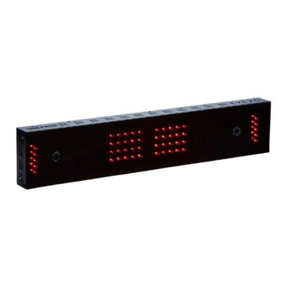
Check and see if the power is on. You will see a bright red light on the switch of the sensor. Check and see if your EYEXO Sensor and PC are paired through the network. Please refer to our “Network Settings Guide” to set the IP address. -
Page 13: Software Install
5. Software Install Please make sure PC requirements are met from section 1 “Installation Environment,” before the WARNING installation process. Failure to do will result in installation issues and slow gameplay. Please make sure the connection statuses are clear WARNING and everything is paired. - Page 14 USB Software Necessary Part(s) Insert USB - memory stick from the box into your PC. You will receive an email with a license code from support@uneekor.com which looks like this: QED_30000XXXXX.license. Please download it and transfer it to the USB.
- Page 15 1. The 3 softwares from the “Required Software” section: “Aio-runtimes,” “Teamviewer10,” and “DirectX.” 2. The 2 softwares from “Sensor Software” section: “EYEXO Sensor & EYEXO Activation” 3. Software Section: “VIEW,” “QED Succeed.” This will depend on your purchase. Please install each software one at a time.
- Page 16 5.3 Software Install - Continued Please select all “Visual C++ rest. These ”Visual C++ Runtime and the game. Then Click “Install.” (If you do not see the “Visual already has these downloaded from another install) Alo-runtimes Please select “Basic Installation” and “Personal/ non-commericial use”...
- Page 17 5.4 Software Install - Continued Click “Finish” when the download is complete. Direct X Click “Next” to start the EYEXO Sensor install in the setup window. EYEXO Sensor Default destination folder will be in C: Drive. If you would like to change the destination click “Browse...”...
- Page 18 5.5 Software Install - Continued You will see this screen once the install has started. The “Run EYEXO Sensor is checked. Uncheck it and click ”Finish.” license key. Then click “Activation.” QED_30000XXXXX.license Continued on page 19 EYEXO Activation E Y E X O I N S T A L L G U I D E...
- Page 19 “EYEXOSensor” > Open “EYEXO_U_Activation.” > Browse Depending on what package you purchased/paid for, you will be only allowed to install. NOTE: All EYEXO sensors come with “VIEW” software. Install “VIEW” software REFINE,” or “QED SUCCEED,” depending on your purchase. QED Software...
- Page 20 5.7 Software Install - Continued Click the “VIEW 1.0 Then click the “Install” button on the next window. VIEW Activation License file from step 4, then click activation. “Finish” QED_30000XXXXX.license E Y E X O I N S T A L L G U I D E...
- Page 21 If activation was successful you will see this window. If activation failed, please contact support@uneekor. com. software installation and ready for calibration. E Y E X O I N S T A L L G U I D E...
-
Page 22: Club Sticker Guide
EYEXO VIEW Club Data Club Speed The speed of the club before impact. Ball Speed divided by Club Speed The angle difference between Face Angle and Club Path. E Y E X O I N S T A L L G U I D E... - Page 23 EYEXO VIEW Club Data The up and down movement of the club head at the time of impact. Attack angle is measured relative to the horizon. The in to out or out to in movement of the club head’s geometric center at the time of impact.
- Page 24 EYEXO VIEW Club Data The amount of loft of the club face at the center point of impact. Lie angle is the angle created between the center of the shaft and ground when you put your iron down in the address position.
- Page 25 EYEXO VIEW Club and Sticker Placement E Y E X O I N S T A L L G U I D E...
- Page 26 EYEXO VIEW Sticker Placement 2 - 2.4 inches Driver 8 groove 1.) The position closest to the horizontal center line should be used as a reference. 2.) The height of the sticker placement should be the same for both. 3.) Avoid placing both stickers near the sweet spot 5.) Attach in line with the grooves.
- Page 27 EYEXO VIEW Sticker Application 1 Center Groove The stick must not cross or bend over the leading edge. The sticker must be attach inside the club face for proper reading. All 4 corners of the stickers must be attached to the club face. If the club face is short and all 4 horiztonal line so all of the Bar Sticker can be placed inside he club face.
- Page 28 EYEXO VIEW Sticker Application 2 All 4 corners of the stickers should be attached inside the club face. If there is an aim marker on the crown of the driver, use it as reference for the vertical center line. The top of the bar and dot sticker must be aligned with the horizontal center line.
- Page 29 Items Contents Components 2 Hyper Speed Cameras 2 Infrared LED Boards 1 Control Board 1 Power Board Data Interface Ethernet (CAT6 and above) Communication Speed 1 Gbps Spin Data Total Spin ±12,000 rpm Ball Speed Putter: 0.1 m/s ~ 30 m/s Measurement Range Ball Speed Driver/Iron: 5 m/s ~ 100 m/s Driver: -5 ~ 50 Degree...
- Page 30 Uneekor, Inc. 26249 Enterprise Court Lake Forest, CA 92630 Tel: 1-949-328-7790 sales@uneekor.com support@uneekor.com Uneekor © 2020 All Rights Reserved...
Need help?
Do you have a question about the EYEXO and is the answer not in the manual?
Questions and answers